EP1238871A2 - Gassack-Modul - Google Patents
Gassack-Modul Download PDFInfo
- Publication number
- EP1238871A2 EP1238871A2 EP02004304A EP02004304A EP1238871A2 EP 1238871 A2 EP1238871 A2 EP 1238871A2 EP 02004304 A EP02004304 A EP 02004304A EP 02004304 A EP02004304 A EP 02004304A EP 1238871 A2 EP1238871 A2 EP 1238871A2
- Authority
- EP
- European Patent Office
- Prior art keywords
- diffuser
- gas generator
- receiving housing
- flange
- airbag
- Prior art date
- Legal status (The legal status is an assumption and is not a legal conclusion. Google has not performed a legal analysis and makes no representation as to the accuracy of the status listed.)
- Withdrawn
Links
Images
Classifications
-
- B—PERFORMING OPERATIONS; TRANSPORTING
- B60—VEHICLES IN GENERAL
- B60R—VEHICLES, VEHICLE FITTINGS, OR VEHICLE PARTS, NOT OTHERWISE PROVIDED FOR
- B60R21/00—Arrangements or fittings on vehicles for protecting or preventing injuries to occupants or pedestrians in case of accidents or other traffic risks
- B60R21/02—Occupant safety arrangements or fittings, e.g. crash pads
- B60R21/16—Inflatable occupant restraints or confinements designed to inflate upon impact or impending impact, e.g. air bags
- B60R21/20—Arrangements for storing inflatable members in their non-use or deflated condition; Arrangement or mounting of air bag modules or components
- B60R21/217—Inflation fluid source retainers, e.g. reaction canisters; Connection of bags, covers, diffusers or inflation fluid sources therewith or together
-
- B—PERFORMING OPERATIONS; TRANSPORTING
- B60—VEHICLES IN GENERAL
- B60R—VEHICLES, VEHICLE FITTINGS, OR VEHICLE PARTS, NOT OTHERWISE PROVIDED FOR
- B60R21/00—Arrangements or fittings on vehicles for protecting or preventing injuries to occupants or pedestrians in case of accidents or other traffic risks
- B60R21/02—Occupant safety arrangements or fittings, e.g. crash pads
- B60R21/16—Inflatable occupant restraints or confinements designed to inflate upon impact or impending impact, e.g. air bags
- B60R21/20—Arrangements for storing inflatable members in their non-use or deflated condition; Arrangement or mounting of air bag modules or components
- B60R21/203—Arrangements for storing inflatable members in their non-use or deflated condition; Arrangement or mounting of air bag modules or components in steering wheels or steering columns
- B60R21/2035—Arrangements for storing inflatable members in their non-use or deflated condition; Arrangement or mounting of air bag modules or components in steering wheels or steering columns using modules containing inflator, bag and cover attachable to the steering wheel as a complete sub-unit
- B60R21/2037—Arrangements for storing inflatable members in their non-use or deflated condition; Arrangement or mounting of air bag modules or components in steering wheels or steering columns using modules containing inflator, bag and cover attachable to the steering wheel as a complete sub-unit the module or a major component thereof being yieldably mounted, e.g. for actuating the horn switch or for protecting the driver in a non-deployment situation
-
- B—PERFORMING OPERATIONS; TRANSPORTING
- B60—VEHICLES IN GENERAL
- B60R—VEHICLES, VEHICLE FITTINGS, OR VEHICLE PARTS, NOT OTHERWISE PROVIDED FOR
- B60R21/00—Arrangements or fittings on vehicles for protecting or preventing injuries to occupants or pedestrians in case of accidents or other traffic risks
- B60R21/02—Occupant safety arrangements or fittings, e.g. crash pads
- B60R21/16—Inflatable occupant restraints or confinements designed to inflate upon impact or impending impact, e.g. air bags
- B60R21/26—Inflatable occupant restraints or confinements designed to inflate upon impact or impending impact, e.g. air bags characterised by the inflation fluid source or means to control inflation fluid flow
- B60R21/261—Inflatable occupant restraints or confinements designed to inflate upon impact or impending impact, e.g. air bags characterised by the inflation fluid source or means to control inflation fluid flow with means other than bag structure to diffuse or guide inflation fluid
Definitions
- the invention relates to an airbag module, with a receiving housing for a gas bag, a gas generator and a cup-shaped diffuser that the Gas generator surrounds and limited a space for the gas bag.
- Such gas bag modules are used in particular in the steering wheel of the vehicle used.
- the diffuser delimits an annular radially on the inside Receiving space for the gas bag, the receiving space being radially outside of a side wall of the receiving housing is defined.
- a base plate is attached to the receiving housing, on which the diffuser, the Gas generator and a retaining ring possibly arranged in the interior of the gas bag are attached.
- the object of the invention is to provide an airbag module that is easier is constructed and, above all, allows very simple assembly.
- the diffuser has a radial flange with which it is directly on Receiving housing is attached and an annular bottom for Closing the receptacle forms, and that the diffuser inside of the receiving housing and a gas generator room open from the bottom forms.
- the diffuser forms the base for the receptacle so that the base plate described above is complete can be omitted.
- the diffuser also closes the housing forms, a gas generator room open from the side of the floor arise, so that the gas generator at the end of the assembly simply in the bottom introduced the gas generator room, so to speak as the last part to be assembled can be. It is also possible to make the desired as long as possible Separation in handling between the gas generator and the remaining gas bag module to ensure.
- the gas generator is inserted into the bottom of the gas generator room and on Flange of the diffuser attached. The attachment from below creates a good one Accessibility for the fasteners.
- the gas generator is preferably located completely in the gas generator room.
- the flange of the diffuser has one bent, axial end edge, with which he on the side wall of the Receiving housing is attached.
- the receptacle therefore does not have to be radial have inwardly projecting portion which forms part of the bottom, which the Manufacture of the receiving housing facilitated.
- the receiving housing preferably consists of a circumferential Side wall and a one-piece molded front wall with a predetermined opening flap for the exit of the gas bag.
- the opening flap is formed in that the front wall with predetermined tear lines Has material weakening zones.
- the gas bag module is largely through only two easy-to-manufacture parts are formed, namely by the receiving housing, which is cup-shaped, and the cup-shaped diffuser, the is inserted from the back and its flange on the side wall the receiving housing is attached.
- the gas bag is attached to the gas bag module, for example by means of a retaining ring arranged in the interior of the gas bag, which is on the flange the diffuser is attached.
- the retaining ring then holds the edge of the so-called Injection opening, through which gas flows into the interior of the gas bag, on the gas bag module.
- the gas bag module is also preferred with a vibration damper equipped by the gas generator via an elastomeric damping part with its Mounting flange is connected.
- the inside of the diffuser can then Swing the gas generator undisturbed because it is at a sufficient distance to the diffuser.
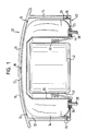
- the drawing shows a schematic cross section by an airbag module according to the invention.
- an airbag module for a vehicle steering wheel is shown, the one Pot-shaped receiving housing 10 with a front wall 12 and one piece molded on it, circumferential side wall 14.
- the front wall 12 has a plurality of weakening zones 16 that define a plurality of opening flaps 18 that Form sections of the front wall 12.
- the gas bag module also has a cup-shaped diffuser 20, which is inserted into the receiving housing 10 from the open bottom side 22 thereof is.
- the diffuser has a radial flange 24 at its bottom end extends outwards to the side wall 14 and in this area a bent, has axially extending end edge 26 on which it has a snap connection 28 or a screw connection 30 is fixedly attached to the receiving housing 10.
- the flange 24 closes approximately flush with the lower edge of the side wall 14 and forms an annular bottom for closing the receiving housing 10, because the diffuser 20 is open on the back and thus has one Inlet opening for the gas generator 42.
- the diffuser is a sheet metal part that has several flow openings and from the gas generator laterally as well as axially is spaced.
- a closed space is formed, which as an annular receiving space 32 for an airbag 34 is designated.
- an annular receiving space 32 for an airbag 34 is designated.
- a retaining ring 36 is arranged on the back protruding threaded bolt 38 can be attached.
- the retaining bolts 38 extend through openings in flange 24.
- a bottom open gas generator space 40 is formed. From the bottom, the Assembly simply inserted a gas generator 42 into the gas generator space 40.
- the Gas generator 40 has a cylindrical shape and one first toward the Bottom and then radially outward fastening flange 44.
- the mounting flange 44 is an elastomeric damping member 46 with the Gas generator 42 coupled to the gas generator 42 vibration-isolated in To accommodate gas generator room 40.
- the mounting flange 44 is on the bottom side directly on the flange 24, and the bolts 38 also protrude corresponding openings in the mounting flange 44.
- the bolts 38 can also be used to attach the entire module to the Steering wheel can be used.
- the gas bag module shown is very simple and consists of very few, easy to assemble parts.
- the stability of the housing is achieved by the diffuser 20, the flange 24 of the bottom of the receiving housing forms and closes this.
- the gas bag module is very short axially because the gas generator 42 is stationary not in front of the receptacle housing.
Landscapes
- Engineering & Computer Science (AREA)
- Mechanical Engineering (AREA)
- Physics & Mathematics (AREA)
- Fluid Mechanics (AREA)
- Air Bags (AREA)
Abstract
Description
Claims (6)
- Gassack-Modul,dadurch gekennzeichnet, daß der Diffusor (20) einen radialen Flansch (24) hat, mit dem er unmittelbar am Aufnahmegehäuse (10) befestigt ist und der einen ringförmigen Boden (24) zum Verschließen des Aufnahmegehäuses (10) bildet, undmit einem Aufnahmegehäuse (10) für einen Gassack (34),einem Gasgenerator (42) undeinem topfförmigen Diffusor (20), der den Gasgenerator (42) umgibt und einen Aufnahmeraum (32) für den Gassack (34) beschränkt,
daß der Diffusor (20) in das Innere des Aufnahmegehäuses (10) ragt und einen von Seiten des Bodens aus offenen Gasgeneratorraum (40) bildet. - Gassack-Modul nach Anspruch 1, dadurch gekennzeichnet, daß der Gasgenerator (42) bodenseitig in den Gasgeneratorraum (40) eingeführt und am Flansch (24) des Diffusors (20) befestigt ist.
- Gassack-Modul nach Anspruch 1 oder 2, dadurch gekennzeichnet, daß der Flansch (24) des Diffusors (20) einen umgebogenen, axialen Abschlußrand (26) hat, mit dem er an einer Seitenwand (14) des Aufnahmegehäuses (10) befestigt ist.
- Gassack-Modul nach einem der vorhergehenden Ansprüche, dadurch gekennzeichnet, daß das Aufnahmegehäuse (10) aus einer umlaufenden Seitenwand (14) und einer einstückig daran angeformten Frontwand (12) mit einer vorgegebenen Öffnungsklappe (18) zum Austritt des Gassacks (34) besteht.
- Gassack-Modul nach einem der vorhergehenden Ansprüche, dadurch gekennzeichnet, daß der Gassack (34) mittels eines in seinem Inneren angeordneten Halterings (36) am Flansch (24) des Diffusors (20) befestigt ist.
- Gassack-Modul nach einem der vorhergehenden Ansprüche, dadurch gekennzeichnet, daß der Gasgenerator (42) über ein elastomeres Dämpfungsteil (46) mit seinem Befestigungsflansch (44), mit dem er am Flansch (24) befestigt ist, verbunden ist.
Applications Claiming Priority (2)
| Application Number | Priority Date | Filing Date | Title |
|---|---|---|---|
| DE20104044U | 2001-03-08 | ||
| DE20104044U DE20104044U1 (de) | 2001-03-08 | 2001-03-08 | Gassack-Modul |
Publications (2)
| Publication Number | Publication Date |
|---|---|
| EP1238871A2 true EP1238871A2 (de) | 2002-09-11 |
| EP1238871A3 EP1238871A3 (de) | 2003-07-16 |
Family
ID=7954025
Family Applications (1)
| Application Number | Title | Priority Date | Filing Date |
|---|---|---|---|
| EP02004304A Withdrawn EP1238871A3 (de) | 2001-03-08 | 2002-02-28 | Gassack-Modul |
Country Status (3)
| Country | Link |
|---|---|
| US (1) | US20020125704A1 (de) |
| EP (1) | EP1238871A3 (de) |
| DE (1) | DE20104044U1 (de) |
Cited By (1)
| Publication number | Priority date | Publication date | Assignee | Title |
|---|---|---|---|---|
| US9687646B2 (en) | 2007-07-05 | 2017-06-27 | Baxter International Inc. | Peritoneal dialysis connection system and method for using ultraviolet light emitting diodes |
Families Citing this family (6)
| Publication number | Priority date | Publication date | Assignee | Title |
|---|---|---|---|---|
| DE10230140A1 (de) * | 2002-07-04 | 2004-01-15 | Trw Automotive Safety Systems Gmbh & Co. Kg | Gassackmodul |
| DE102004008043A1 (de) * | 2004-02-19 | 2005-09-15 | Autoliv Development Ab | Airbagmodul mit einem schwingungsgedämpften Gasgenerator |
| EP2995512B1 (de) * | 2014-09-11 | 2017-11-15 | Dalphi Metal España, S.A. | Airbagmodul, Halter und Anordnung eines Airbagmoduls und Lenkrad |
| JP6753380B2 (ja) * | 2017-09-28 | 2020-09-09 | 豊田合成株式会社 | エアバッグ装置 |
| JP6948010B2 (ja) | 2017-11-08 | 2021-10-13 | Joyson Safety Systems Japan株式会社 | エアバッグ装置 |
| CN118991664B (zh) * | 2024-09-09 | 2026-03-20 | 均胜汽车安全系统(安徽)有限公司 | 一种方向盘气囊模块 |
Family Cites Families (8)
| Publication number | Priority date | Publication date | Assignee | Title |
|---|---|---|---|---|
| US5762360A (en) * | 1996-10-31 | 1998-06-09 | General Motors Corporation | Air bag assembly |
| DE19804579C2 (de) * | 1998-02-05 | 2001-12-06 | Breed Automotive Tech | Airbag-Modul |
| US6155599A (en) | 1998-08-11 | 2000-12-05 | Trw Vehicle Safety Systems Inc. | Retaining ring with gas diffuser |
| DE19840998B4 (de) * | 1998-09-08 | 2008-01-24 | Takata-Petri Ag | Airbaganordnung bei Fahrzeugen |
| DE19843191A1 (de) | 1998-09-15 | 2000-03-23 | Petri Ag | Airbagmodul |
| US6089600A (en) * | 1998-09-24 | 2000-07-18 | General Motors Corporation | Integral gas direction device for an air bag |
| DE19858691B4 (de) * | 1998-12-18 | 2010-01-07 | Delphi Automotive Systems Deutschland Gmbh | Luftsackmodul für Kraftfahrzeuge |
| DE29902033U1 (de) | 1999-02-05 | 1999-04-08 | TRW Automotive Safety Systems GmbH, 63743 Aschaffenburg | Airbagmodul als Schwingungsdämpfer |
-
2001
- 2001-03-08 DE DE20104044U patent/DE20104044U1/de not_active Expired - Lifetime
-
2002
- 2002-02-28 EP EP02004304A patent/EP1238871A3/de not_active Withdrawn
- 2002-03-04 US US10/090,393 patent/US20020125704A1/en not_active Abandoned
Cited By (1)
| Publication number | Priority date | Publication date | Assignee | Title |
|---|---|---|---|---|
| US9687646B2 (en) | 2007-07-05 | 2017-06-27 | Baxter International Inc. | Peritoneal dialysis connection system and method for using ultraviolet light emitting diodes |
Also Published As
| Publication number | Publication date |
|---|---|
| US20020125704A1 (en) | 2002-09-12 |
| EP1238871A3 (de) | 2003-07-16 |
| DE20104044U1 (de) | 2001-07-12 |
Similar Documents
| Publication | Publication Date | Title |
|---|---|---|
| EP0622276B1 (de) | Gassack-Rückhaltesystem für Fahrzeuge | |
| EP0470330B1 (de) | Ansaugluftfilter für die Verbrennungskraftmaschine eines Fahrzeugs | |
| EP2337710B1 (de) | Gasgenerator für ein airbagmodul | |
| DE102012109545A1 (de) | "Gehäuse für einen Ventilator oder Lüfter" | |
| DE202014008432U1 (de) | Vorrichtung zur schwingfähigen Befestigung eines Gasgenerators in einem Airbagmodul | |
| DE102008060305A1 (de) | Gasgenerator | |
| EP0856437B1 (de) | Gehäuse für den Gassack in einem Kraftfahrzeug | |
| EP1238871A2 (de) | Gassack-Modul | |
| EP3842296B1 (de) | Schwingungstilgerring sowie gassackmodul mit einem solchen schwingungstilgerring | |
| DE19743615B4 (de) | Airbagbaueinheit | |
| EP1167742A2 (de) | Ansaugluftfilter | |
| DE10215330C1 (de) | Airbagmodul mit elastisch gelagertem Gasgenerator | |
| DE102008036272B4 (de) | Gassackmodul | |
| DE102007006571A1 (de) | Gassackmodul | |
| EP2542325B1 (de) | Ölnebelabscheider mit wenigstens einem zyklon | |
| EP0884225A1 (de) | Gassack-Modul für ein Fahrzeuginsassen-Rückhaltesystem | |
| DE102017119335A1 (de) | Gassackmodul für ein fahrzeuglenkrad | |
| DE4303694B4 (de) | Flüssigkeitsfilter mit Überströmventil | |
| DE102010053175A1 (de) | Airbageinrichtung | |
| DE19648137C2 (de) | Airbagmodul | |
| DE2932440A1 (de) | Hydrolager | |
| EP0875425A2 (de) | Umhüllung für Beifahrer-Airbag-Modul | |
| DE202006003235U1 (de) | Gassackmodul | |
| DE102020103502B3 (de) | Radzierblende | |
| DE102022128943A1 (de) | Kraftfahrzeug |
Legal Events
| Date | Code | Title | Description |
|---|---|---|---|
| PUAI | Public reference made under article 153(3) epc to a published international application that has entered the european phase |
Free format text: ORIGINAL CODE: 0009012 |
|
| AK | Designated contracting states |
Kind code of ref document: A2 Designated state(s): AT BE CH CY DE DK ES FI FR GB GR IE IT LI LU MC NL PT SE TR |
|
| AX | Request for extension of the european patent |
Free format text: AL;LT;LV;MK;RO;SI |
|
| PUAL | Search report despatched |
Free format text: ORIGINAL CODE: 0009013 |
|
| AK | Designated contracting states |
Designated state(s): AT BE CH CY DE DK ES FI FR GB GR IE IT LI LU MC NL PT SE TR |
|
| AX | Request for extension of the european patent |
Extension state: AL LT LV MK RO SI |
|
| AKX | Designation fees paid | ||
| REG | Reference to a national code |
Ref country code: DE Ref legal event code: 8566 |
|
| STAA | Information on the status of an ep patent application or granted ep patent |
Free format text: STATUS: THE APPLICATION IS DEEMED TO BE WITHDRAWN |
|
| 18D | Application deemed to be withdrawn |
Effective date: 20040117 |