EP1238776A2 - Methode und Vorrichtung zur Erzeugung eines einteiligen Batteriegehäuses - Google Patents
Methode und Vorrichtung zur Erzeugung eines einteiligen Batteriegehäuses Download PDFInfo
- Publication number
- EP1238776A2 EP1238776A2 EP02004586A EP02004586A EP1238776A2 EP 1238776 A2 EP1238776 A2 EP 1238776A2 EP 02004586 A EP02004586 A EP 02004586A EP 02004586 A EP02004586 A EP 02004586A EP 1238776 A2 EP1238776 A2 EP 1238776A2
- Authority
- EP
- European Patent Office
- Prior art keywords
- core
- mold
- platen
- central core
- jar
- Prior art date
- Legal status (The legal status is an assumption and is not a legal conclusion. Google has not performed a legal analysis and makes no representation as to the accuracy of the status listed.)
- Withdrawn
Links
- 238000000034 method Methods 0.000 title claims abstract description 32
- 239000000463 material Substances 0.000 claims abstract description 57
- 239000003381 stabilizer Substances 0.000 claims abstract description 34
- 238000000605 extraction Methods 0.000 claims abstract description 21
- 238000001746 injection moulding Methods 0.000 claims description 16
- 239000003795 chemical substances by application Substances 0.000 claims description 6
- 238000013022 venting Methods 0.000 claims description 3
- 239000012778 molding material Substances 0.000 claims description 2
- 230000000087 stabilizing effect Effects 0.000 claims 3
- 230000001007 puffing effect Effects 0.000 claims 2
- 230000003213 activating effect Effects 0.000 claims 1
- 230000013011 mating Effects 0.000 claims 1
- 238000007789 sealing Methods 0.000 claims 1
- 238000002347 injection Methods 0.000 abstract description 21
- 239000007924 injection Substances 0.000 abstract description 21
- 238000000465 moulding Methods 0.000 abstract description 10
- 239000011162 core material Substances 0.000 description 73
- 239000004033 plastic Substances 0.000 description 12
- 229920003023 plastic Polymers 0.000 description 12
- 238000004519 manufacturing process Methods 0.000 description 8
- 238000003466 welding Methods 0.000 description 6
- 229920005606 polypropylene copolymer Polymers 0.000 description 5
- 229910000831 Steel Inorganic materials 0.000 description 4
- 239000002253 acid Substances 0.000 description 4
- 239000010959 steel Substances 0.000 description 4
- 239000012530 fluid Substances 0.000 description 3
- 238000012856 packing Methods 0.000 description 2
- 239000002861 polymer material Substances 0.000 description 2
- 229920001296 polysiloxane Polymers 0.000 description 2
- 125000006850 spacer group Chemical group 0.000 description 2
- 229910000906 Bronze Inorganic materials 0.000 description 1
- 241001137350 Fratercula Species 0.000 description 1
- 230000005483 Hooke's law Effects 0.000 description 1
- 239000004743 Polypropylene Substances 0.000 description 1
- 239000004699 Ultra-high molecular weight polyethylene Substances 0.000 description 1
- 239000010974 bronze Substances 0.000 description 1
- 238000010276 construction Methods 0.000 description 1
- 229920001577 copolymer Polymers 0.000 description 1
- KUNSUQLRTQLHQQ-UHFFFAOYSA-N copper tin Chemical compound [Cu].[Sn] KUNSUQLRTQLHQQ-UHFFFAOYSA-N 0.000 description 1
- 230000007812 deficiency Effects 0.000 description 1
- 230000001419 dependent effect Effects 0.000 description 1
- 238000006073 displacement reaction Methods 0.000 description 1
- 238000009826 distribution Methods 0.000 description 1
- 238000003780 insertion Methods 0.000 description 1
- 230000037431 insertion Effects 0.000 description 1
- 238000012986 modification Methods 0.000 description 1
- 230000004048 modification Effects 0.000 description 1
- -1 polypropylene Polymers 0.000 description 1
- 229920001155 polypropylene Polymers 0.000 description 1
- 238000006748 scratching Methods 0.000 description 1
- 230000002393 scratching effect Effects 0.000 description 1
- 238000000926 separation method Methods 0.000 description 1
- 238000006467 substitution reaction Methods 0.000 description 1
- 229920000785 ultra high molecular weight polyethylene Polymers 0.000 description 1
Images


Classifications
-
- B—PERFORMING OPERATIONS; TRANSPORTING
- B29—WORKING OF PLASTICS; WORKING OF SUBSTANCES IN A PLASTIC STATE IN GENERAL
- B29C—SHAPING OR JOINING OF PLASTICS; SHAPING OF MATERIAL IN A PLASTIC STATE, NOT OTHERWISE PROVIDED FOR; AFTER-TREATMENT OF THE SHAPED PRODUCTS, e.g. REPAIRING
- B29C45/00—Injection moulding, i.e. forcing the required volume of moulding material through a nozzle into a closed mould; Apparatus therefor
- B29C45/17—Component parts, details or accessories; Auxiliary operations
- B29C45/26—Moulds
-
- B—PERFORMING OPERATIONS; TRANSPORTING
- B29—WORKING OF PLASTICS; WORKING OF SUBSTANCES IN A PLASTIC STATE IN GENERAL
- B29C—SHAPING OR JOINING OF PLASTICS; SHAPING OF MATERIAL IN A PLASTIC STATE, NOT OTHERWISE PROVIDED FOR; AFTER-TREATMENT OF THE SHAPED PRODUCTS, e.g. REPAIRING
- B29C33/00—Moulds or cores; Details thereof or accessories therefor
- B29C33/56—Coatings, e.g. enameled or galvanised; Releasing, lubricating or separating agents
- B29C33/58—Applying the releasing agents
-
- B—PERFORMING OPERATIONS; TRANSPORTING
- B29—WORKING OF PLASTICS; WORKING OF SUBSTANCES IN A PLASTIC STATE IN GENERAL
- B29C—SHAPING OR JOINING OF PLASTICS; SHAPING OF MATERIAL IN A PLASTIC STATE, NOT OTHERWISE PROVIDED FOR; AFTER-TREATMENT OF THE SHAPED PRODUCTS, e.g. REPAIRING
- B29C45/00—Injection moulding, i.e. forcing the required volume of moulding material through a nozzle into a closed mould; Apparatus therefor
- B29C45/17—Component parts, details or accessories; Auxiliary operations
- B29C45/26—Moulds
- B29C45/36—Moulds having means for locating or centering cores
-
- B—PERFORMING OPERATIONS; TRANSPORTING
- B29—WORKING OF PLASTICS; WORKING OF SUBSTANCES IN A PLASTIC STATE IN GENERAL
- B29C—SHAPING OR JOINING OF PLASTICS; SHAPING OF MATERIAL IN A PLASTIC STATE, NOT OTHERWISE PROVIDED FOR; AFTER-TREATMENT OF THE SHAPED PRODUCTS, e.g. REPAIRING
- B29C45/00—Injection moulding, i.e. forcing the required volume of moulding material through a nozzle into a closed mould; Apparatus therefor
- B29C45/17—Component parts, details or accessories; Auxiliary operations
- B29C45/40—Removing or ejecting moulded articles
- B29C45/43—Removing or ejecting moulded articles using fluid under pressure
-
- H—ELECTRICITY
- H01—ELECTRIC ELEMENTS
- H01M—PROCESSES OR MEANS, e.g. BATTERIES, FOR THE DIRECT CONVERSION OF CHEMICAL ENERGY INTO ELECTRICAL ENERGY
- H01M50/00—Constructional details or processes of manufacture of the non-active parts of electrochemical cells other than fuel cells, e.g. hybrid cells
- H01M50/10—Primary casings; Jackets or wrappings
-
- B—PERFORMING OPERATIONS; TRANSPORTING
- B29—WORKING OF PLASTICS; WORKING OF SUBSTANCES IN A PLASTIC STATE IN GENERAL
- B29C—SHAPING OR JOINING OF PLASTICS; SHAPING OF MATERIAL IN A PLASTIC STATE, NOT OTHERWISE PROVIDED FOR; AFTER-TREATMENT OF THE SHAPED PRODUCTS, e.g. REPAIRING
- B29C45/00—Injection moulding, i.e. forcing the required volume of moulding material through a nozzle into a closed mould; Apparatus therefor
- B29C45/17—Component parts, details or accessories; Auxiliary operations
- B29C45/40—Removing or ejecting moulded articles
- B29C2045/4078—Removing or ejecting moulded articles using stripping means
-
- Y—GENERAL TAGGING OF NEW TECHNOLOGICAL DEVELOPMENTS; GENERAL TAGGING OF CROSS-SECTIONAL TECHNOLOGIES SPANNING OVER SEVERAL SECTIONS OF THE IPC; TECHNICAL SUBJECTS COVERED BY FORMER USPC CROSS-REFERENCE ART COLLECTIONS [XRACs] AND DIGESTS
- Y02—TECHNOLOGIES OR APPLICATIONS FOR MITIGATION OR ADAPTATION AGAINST CLIMATE CHANGE
- Y02E—REDUCTION OF GREENHOUSE GAS [GHG] EMISSIONS, RELATED TO ENERGY GENERATION, TRANSMISSION OR DISTRIBUTION
- Y02E60/00—Enabling technologies; Technologies with a potential or indirect contribution to GHG emissions mitigation
- Y02E60/10—Energy storage using batteries
Definitions
- the invention relates to the field of industrial battery cases. More particularly, the invention relates to a method and apparatus for making a one-piece battery jar having at least a thicker section at the opening thereof than at other areas of the jar.
- Lead-acid batteries are used in industry to power vehicles such as fork-lifts. Since a single lead-acid cell has a potential of 2 volts, the higher voltages suitable for motors are attained by packing a number of cells upright, side-by-side, in a steel tray, and connecting them electrically in series.
- each 2-volt cell is enclosed in its own container which consists of a "jar” whose upper end is initially open to allow insertion of the battery-plate assembly, and a cover, which is welded onto the top of the jar after the battery-plate assembly has been inserted.
- the plates of a motive-power lead-acid battery must be pressed tightly against each other to minimize the shedding of plate material.
- the outside of a jar is preferably a rectangular prism. This shape enables the cells to be tightly packed in a rectangular tray made of a material that will maintain the packing pressure during the life of the battery.
- the trays are made of steel.
- the inside walls of the jar which press against the plates, need to provide the same pressure at the top and the bottom of the plates. This requires the jar to have the same inner dimensions at its top and its bottom. If the jar is molded with "draft" where the top is wider than the bottom, the plates may be pressed tightly together at the bottom, but not tightly packed at the top. The less than optimum pressure between the plates at the top results in relatively more shedding of material and shorter battery life.
- the above qualities have to be provided at the lowest cost. This requires that a minimum of material be used, that lower cost reprocessed material be used if possible, and that the manufacturing process be relatively low cost.
- Battery jars have long been made by injection-molding them in one-piece with some degree of draft from polypropylene co-polymer material.
- the material is injected at the bottom of the jar and flows toward the open end.
- This is a high value for injection molding and for polypropylene co-polymer materials having melt-indices low enough so that they do not stick to the hot-plate welding platens. It results in very high injection and mold pressures.
- the inventor hereof created a profiled wall battery jar.
- the jar employs thicker material at the ends of the elongated jar and thinner material at the midsection thereof. This achieves strength yet reduces the amount of material needed. Moreover, and importantly, this provides more space for acid while maintaining strict adherence to the outside dimensions dictated by the conventional mounting areas in machines employing the finished batteries.
- U.S. Patent No. 4,732,826 which is assigned to the assignee hereof and incorporated herein by reference.
- profiled wall battery jars have been molded in half sections and then welded at the seams.
- the welding is generally of the hot plate type and is in two steps: first to join the two halves and second, to create a three-layer structure in the joint.
- the operation is particularly suited to providing a leak-free joint but is relatively labor intensive which, of course, increases cost of manufacture. It has been desired to reduce the labor associated with producing profiled battery jars while retaining the benefits thereof. Heretofore, it was not known how such benefits could all be achieved.
- the apparatus for making the one-piece battery jar employs a core having exterior features matching the desired profile for the interior of the jar to be molded (The "profile" may be anything from undercut to straight wall).
- the core is mounted on a carrier which positions it reliably between two platens having plastic material supply.
- the platens comprise a stationary platen and a moving platen.
- the carrier is mechanically linked to the platens in such a way that it is always centered between the platens.
- the core thus stays centered between the mold cavities.
- the invention preferably employs a number of core stabilizers that retract immediately before the molding material has completely filled the mold.
- the platens open and an air puffin the range of about >30-40 psi is employed to temporarily stretch the side-walls of the battery jar.
- the separation process is useful regardless of whether features are provided on the core or the core is straight.
- stretching of the plastic is necessary to extract the molded part (in a profiled jar situation) because the central area of the core is larger than the ends of the core forming an "undercut" condition.
- the fingers extend into very close proximity to the core but do not contact it.
- the invention provides one-piece profiled battery jars. Moreover, since no welding is required, a greater percentage (up to 100%) of reclaimed material may be employed. The invention reduces necessary production time for completed jars and reduces costs associated with that production.
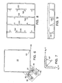
- FIGURE 1 of the invention one of ordinary skill will recognize a typical stack molding centering linkage.
- Such a linkage maintains a portion of the mold assembly 12 in a centered position between a stationary platen 14 and a moving platen 16. The movement is caused by connecting arms 18 and center arm 20 in a known manner.
- a core 22 is provided centrally between a stationary platen 24 and a moving platen 26.
- Core 22 which is a replacement for a center platen, is mounted upon core carrier 28 which in turn is mounted to the equivalent of center arm 20 discussed above.
- the core may be straight walled and is capable of producing jars with draft angles that include from negative to positive draft. Zero draft is preferred and possible in the invention.
- Another preferred embodiment employs a core which includes outer features to produce a profiled battery jar wherein a longitudinally central area is of a thinner thickness and at least the longitudinally open end of the jar is of a greater thickness.
- Core 22 is positioned between each platen 24, 26 as noted and each platen preferably includes a spacer 30, 32 attached thereto, a hot manifold 34, 36 (for plastic distribution) and a cavity block 38, 40.
- a cavity is formed around core 22 which conforms to the outer shape of the part desired.
- the cavity is sealed prior to injection of material by shut-off ring 42. The cavity is thus sealed and ready for injection of material.
- Core 22 is preferably positioned vertically and in such a manner as to form a jar with the open end pointing downwardly.
- the preferred material for the invention is a polypropylene co-polymer.
- the material is flowed into the cavity through preferably four injectors 44 on each hot manifold 34, 36.
- Four injectors 44 are preferred on each side of the mold because of the longitudinal length of the mold cavity.
- batteries require molded jars of up to 29 inches in length.
- Plastic material is directly suppliable to the hot manifold on the stationary platen and indirectly, i.e. via a sprue bar, to the hot manifold on the moving platen.
- the material is maintained at molding temperature in the respective hot manifolds and then injected into the cavity created by cavity blocks 38, 40, core 22 and shutoff ring 42.
- Core locks 39 project from the mold cavity wall to prevent deflection during injection and can be withdrawn in about 30-40 milliseconds of the last 100 milliseconds of injection.
- the plastic material is injected into the mold at locations A 1 , A 2 , A 3 and A 4 on the stationary half of the mold and at locations B 1 , B 2 , B 3 and B 4 on the moving half of the mold.
- a 2 and A 3 disks for example, have attained radii equal to one-half of the distance between A 2 and A 3 , the upper edge of the A 2 disk and the lower edge of the A 3 disk knit together. Then the material in the two disks flows more and more laterally toward the cavity parting-line 25.
- venting is provided at the cavity parting-line by a 0.001 in. to 0.002 in. gap between the cavity halves. Since the impingement of the A and B plastic material streams is not always precisely at the cavity parting-line, porous steel inserts approximately 1 in. wide are mounted in each cavity along the parting-line, thereby providing a vented area 2 in. wide.
- FIGURE 2B The distance that the plastic material must flow is illustrated in FIGURE 2B.
- a portion of the material moves directly laterally, at 90 ° to the axis of the core.
- the flow-path length is: L 2 + W 2
- another portion has to move at an angle, ⁇ , to the axis of the core until it reaches the edges of the core; then it moves, at 90° to the core axis, to the parting-line between the cavity halves.
- This is the longest flow-path required of the material.
- FIGURE 2C it is: (L 2 + P 2 ) 1/2 + W 2
- the present invention includes a plurality of core stabilizers (see FIGURE 3) which function to hold core 22 in place during the onset of the injection process and then retract immediately before the injection process halts.
- the core stabilizers retract within 50 milliseconds, that time frame being preferably within the last 100 milliseconds of the injection process.
- the core stabilizers, fully retracted, are preferably flush with the wall of the cavity block into which they retract so that the battery jar is smooth on the inner and outer walls thereof.
- Core 22 is stable after withdrawal of the stabilizers (during the time frame identified) because of the volume of plastic material which has positioned itself around core 22 in the mold cavity.
- Core stabilizer of the invention is illustrated.
- Core 22 is illustrated in cross-section from the top. From this description one of skill in the art should appreciate the orientation of the core stabilizers.
- Each core stabilizer is employed as a pair with an oppositely disposed stabilizer on the other side. In the illustration, a single core stabilizer assembly is shown. It will be understood that the other stabilizers are identical.
- Core stabilizer face 62 is illustrated flush with mold cavity block inner face 41. It will be appreciated that face 41 is the exterior surface of the mold cavity, the inner surface of which being provided by core face 23. The face 62 is illustrated in the withdrawn position. More specifically face 62 is flush with inner face 41 so as to make a smooth molded part. This is the position that the stabilizer takes within the last 100 milliseconds of the injection process as above described. One of skill in the art will appreciate the other position of stabilizer 60 to be where face 62 is in contact with surface 23. The stabilizer is in this position during the period of the injection process before the final 100 milliseconds thereof.
- Stabilizer 60 is operated by hydraulic fluid pumped into area 64 which urges the assembly and thus the stabilizer 60 toward core 22.
- the hydraulic fluid pressure overcomes the bias of springs 66 until the release valve 68 dumps pressure in the last 100 milliseconds of the injection process.
- the various parts of the stabilizer illustrated could be a single machined piece but are broken up for assembly purposes. The manufacturing issues surrounding the individual parts are known to one of skill in the art and do not require explanation. It is important to note only that a system of hydraulic pressuring and a dump valve are employed to actuate the core stabilizer of the invention. It has been found that the hydraulic system is "strong" enough to prevent core deflection where prior art stabilizers have failed to be reliable.
- the dump valve 68 is preferably a solenoid actuated pilot operated valve with a 65 GPM nominal flow rating.
- FIG. 70 Another feature of the core stabilizer of the invention is a spacer 70 having castellations thereon.
- Castellations 72 allow for adjustment of the wall thickness of the part to be molded.
- the wall thickness of the battery jar of the invention may have varying wall thickness as desired by changing the outside dimensions of core 22. Since battery jars of the invention are preferably of either a wall thickness of 0.100 in. or 0.060 in., it was desirable that the stabilizer be adapted to easily accommodate either of these sizes.
- the castellation bar 70 provides the adjustability quickly and easily.
- castellation bar 70 is actuatable in a direction perpendicular to the direction of movement of stabilizer 60.
- the stroke of bar 70 is preferably .646 in. in a preferred embodiment but in any event is equivalent to the distance between the center of an upward castellation and the center of a downward castellation such that the stroke of the bar places the bar in a nested position with castellation 74 on stabilizer 60 or in a non-nested position with castellation 74.
- alignment and misalignment of the castellation adjusts the inward movement of stabilizer 60 from 0.060 in. to 0.100 in.
- Bar 70 is preferably actuated pneumatically.
- valve 68' springs 66 urge stabilizer face 62 into the plane of cavity block inside face 41.
- springs 66 With reference to FIGURE 4, it will be apparent that a preferred embodiment employs four springs 66.
- FIGURES 5 and 6 another difficulty presented by the desire to injection mold a single piece battery jar having at least a thicker end wall on the open end of the jar, is that removal requires stretching of the thick piece of the jar.
- the material Upon the passage of a short period of time after the plastic material injection process concludes, the material has hardened sufficiently to be removed from the mold. The shorter this period of time can be, the more productive the machine is. It is preferred to allow the material to cool for about 10 seconds prior to opening the mold.
- an extraction assembly plunges into the mold area around the core and molded part, preferably near the exterior surface of the part and from the closed end of the jar.
- the extraction assembly preferably comprises four arms disposed one at each longitudinal edge or corner of the jar. The positioning of the arms at each of the longitudinal corners is important because the friction coefficient resisting removal of the part from the core is concentrated at these corners. Thus, by positioning an extraction force beneath these corners, successful removal of the part from the core is achieved.
- Each extraction arm 80 includes fingers 82 which are carefully constructed to reach inwardly from the outside surface of the molded jar toward the center thereof to about 90% of the thickness of the wall of the jar. The fingers extend preferably about 1 1/4 inches in either direction from the corner to increase the surface area contacted. The amount of the molded part contacted is relatively large while the fingers 82 remain a safe distance from core 22 so that scratching of the core will not occur.
- FIGURE 5 provides a perspective view of arm 80 while FIGURE 6 is a plan view of an extraction arm 80 in a relative position with respect to core 22.
- FIGURES 5A-5C are expanded views of selected portions of FIGURE 5.
- FIGURE 6 is schematic in that other portions of the mold are not illustrated.
- finger plate 82 is illustrated at the bottom of extraction arm 80 and is mounted to foot 88 by preferably four screws 86 (shown in FIGURE 6). Screws 86 ride in grooves 84 in finger 82. Finger 82 is thus moveable in a single linear direction relative to foot 88.
- a "front" portion thereof is profiled to include a substantially right angle such that finger 82 matches the part to be removed.
- Wiper 90 Dependent from finger 82 is wiper 90.
- Wiper 90 is preferably constructed of felt although other soft wicking material would also be acceptable.
- Wiper 90 is mounted to finger 82 by a wiper plate 92 attached to finger 82.
- wiper 90 is also spring-loaded onto finger 82 to ensure that as wiper 90 wears it will still contact core 22. This is important since wiper 90 automatically applies a release agent such as silicone to the core 22 as the previously molded part is being extracted.
- Wiper 90 is fed by tube 92 from a supply source not shown.
- tube 92 is moveable with finger 82 and thus requires a slot 95 as shown.
- Supporting finger 82, wiper 90 and foot 88 are mounted on frame 94 of preferably a stiff material.
- Frame 94 also locates and supports limiters 96 which bear against the part to be extracted to prevent finger 82 from touching core 22.
- Limiters 96 are preferably made of a low-wear material such as ultra high molecular weight polyethylene.
- frame 94 provides support structures 98 for tube 92 and for the finger actuating arrangement discussed hereunder.
- the finger actuating arrangement comprises a shaft 100 which is fixedly connected to a fork 102 adjacent foot 88 and to a rotational driver at the other end thereof (not shown). Any type of driver (e.g. electrical, mechanical, pneumatic, etc.) may be employed.
- Extraction arm 80 is mounted above the mold cavity so as to allow a mechanism to cause a plurality of extraction arms (preferably 4) to plunge into the mold space upon opening and remove the molded part.
- Air is preferably injected into the part at each side wall and the closed bottom portion of the part.
- the injection of air dislodges the part and assists in its removal from the core.
- air injection alone does not reduce the extraction force to an acceptable level. Therefore, in a preferred embodiment, the discussed wiper 90 is employed.
- the agent being, for example, a silicone fluid
- extraction force can be lowered to less than 1000 pounds as opposed to greater than 2000 pounds. It is important to note that the core 22 will have to be coated with the release agent at corners 83 prior to molding the first jar. The automatic recoating will then take place naturally upon the removal of each molded jar.
- the friction coefficient of polypropylene co-polymer, the preferred material, against (0.060) steel (the likely core material) is approximately 0.20.
- the extraction force for the thin portion of a jar (for exemplary purposes 26.5 inches in a 29 inch jar) can be calculated as is shown by the equations above. The 26.5 inches of material at the four vertical edges would require (408 x 0.20) x 26.5 to extract the section from the core. This translates to 2,162 pounds of extraction force. This number does not take into account the significantly higher friction created by the thick section of the jar which must stretch over the wider portion of the core to be removed. Thus the actual pounds of extraction force needed would far exceed 2,162 pounds.
- the extraction force has been reduced to less than about 1000 pounds. Reducing the friction to the levels disclosed enables faster production and fewer damaged jars.
- the method of the invention employs the apparatus of the invention to quickly and efficiently make single piece profiled (or not) battery jars.
- the bridges molded into the jar of the invention are in the layout of FIGURES 8 and 9.
- the layout is preferred due to its ability to permit the flow of battery mud, i.e., material which is shed principally at the outer edges of the plates, to another chamber thereby avoiding short circuiting caused by mud buildup in a chamber.
- the bridges include upright members 120 and preferably gussets 122 for added strength.
- mud is a limiting factor in the service life a battery. Thus, by providing bridges that accommodate more mud before short circuiting the battery, service life is improved.
Landscapes
- Engineering & Computer Science (AREA)
- Mechanical Engineering (AREA)
- Manufacturing & Machinery (AREA)
- Chemical & Material Sciences (AREA)
- Chemical Kinetics & Catalysis (AREA)
- Electrochemistry (AREA)
- General Chemical & Material Sciences (AREA)
- Moulds For Moulding Plastics Or The Like (AREA)
- Sealing Battery Cases Or Jackets (AREA)
- Injection Moulding Of Plastics Or The Like (AREA)
- Battery Mounting, Suspending (AREA)
- Secondary Cells (AREA)
Applications Claiming Priority (3)
| Application Number | Priority Date | Filing Date | Title |
|---|---|---|---|
| US84771 | 1998-05-26 | ||
| US09/084,771 US6332997B1 (en) | 1998-05-26 | 1998-05-26 | Method and apparatus for making a one piece battery jar |
| EP99925876A EP0999927B1 (de) | 1998-05-26 | 1999-05-26 | Methode und vorrichtung zur erzeugung eines einteiligen batteriegehäuses |
Related Parent Applications (1)
| Application Number | Title | Priority Date | Filing Date |
|---|---|---|---|
| EP99925876A Division EP0999927B1 (de) | 1998-05-26 | 1999-05-26 | Methode und vorrichtung zur erzeugung eines einteiligen batteriegehäuses |
Publications (2)
| Publication Number | Publication Date |
|---|---|
| EP1238776A2 true EP1238776A2 (de) | 2002-09-11 |
| EP1238776A3 EP1238776A3 (de) | 2004-01-07 |
Family
ID=22187116
Family Applications (2)
| Application Number | Title | Priority Date | Filing Date |
|---|---|---|---|
| EP02004586A Withdrawn EP1238776A3 (de) | 1998-05-26 | 1999-05-26 | Methode und Vorrichtung zur Erzeugung eines einteiligen Batteriegehäuses |
| EP99925876A Expired - Lifetime EP0999927B1 (de) | 1998-05-26 | 1999-05-26 | Methode und vorrichtung zur erzeugung eines einteiligen batteriegehäuses |
Family Applications After (1)
| Application Number | Title | Priority Date | Filing Date |
|---|---|---|---|
| EP99925876A Expired - Lifetime EP0999927B1 (de) | 1998-05-26 | 1999-05-26 | Methode und vorrichtung zur erzeugung eines einteiligen batteriegehäuses |
Country Status (10)
| Country | Link |
|---|---|
| US (1) | US6332997B1 (de) |
| EP (2) | EP1238776A3 (de) |
| JP (1) | JP2002509500A (de) |
| CN (1) | CN1113738C (de) |
| AT (1) | ATE223292T1 (de) |
| AU (1) | AU4207799A (de) |
| CA (1) | CA2297952A1 (de) |
| DE (1) | DE69902733T2 (de) |
| ES (1) | ES2183564T3 (de) |
| WO (1) | WO1999061217A1 (de) |
Families Citing this family (7)
| Publication number | Priority date | Publication date | Assignee | Title |
|---|---|---|---|---|
| JP2001006321A (ja) * | 1999-06-22 | 2001-01-12 | Tdk Corp | テープカートリッジ用ケース及びその成形金型 |
| US9672947B2 (en) * | 2004-11-15 | 2017-06-06 | Atomic Energy Of Canada Limited | Finned strainer |
| MY167616A (en) * | 2011-10-28 | 2018-09-20 | Novartis Ag | Method for molding an ophthalmic lens and device for applying a coating to the surface of an ophthalmic lens mold |
| CN106985312A (zh) * | 2017-05-19 | 2017-07-28 | 林兮 | 一种塑胶成型机模具用喷油器 |
| AU201717676S (en) | 2017-12-14 | 2018-01-16 | Dometic Sweden Ab | Zip Puller |
| USD904830S1 (en) | 2017-12-14 | 2020-12-15 | Dometic Sweden Ab | Soft bag cooler |
| CN113427690B (zh) * | 2021-05-18 | 2023-06-02 | 安徽百通达科技医疗用品有限公司 | 一种成品手套脱模用气压枪稳压设备 |
Citations (5)
| Publication number | Priority date | Publication date | Assignee | Title |
|---|---|---|---|---|
| US3853451A (en) * | 1973-08-31 | 1974-12-10 | Cities Service Co | Stripper device for molded articles |
| US4109813A (en) * | 1973-03-21 | 1978-08-29 | Valyi Emery I | Composite plastic container |
| DE3024579A1 (de) * | 1980-03-27 | 1981-10-01 | M C S - F.lli Morandi S.n.c., Molinetto di Mazzano, Brescia | Verfahren zum herstellen durch spritzen von behaeltern aus kunststoffmaterial, insbesondere fuer elektrische batterien und akkumulatoren, und form oder werkzeug zur ausuebung des vorgenannten verfahrens |
| US4732826A (en) * | 1986-12-19 | 1988-03-22 | Hardigg Industries. Inc. | Thick-thin battery jar |
| US5240397A (en) * | 1991-10-01 | 1993-08-31 | Biomedical Polymers, Inc. | Injection molding mechanism for forming a monolithic tubular pipette |
Family Cites Families (21)
| Publication number | Priority date | Publication date | Assignee | Title |
|---|---|---|---|---|
| US3767156A (en) * | 1971-05-17 | 1973-10-23 | Richardson Co | Lock mold assembly for a container mold |
| US3978186A (en) * | 1974-11-25 | 1976-08-31 | Beatrice Foods Co. | Method for making a partitioned container |
| US3947208A (en) * | 1975-03-19 | 1976-03-30 | Broderick Walter M | Article engaging and extracting arrangement for the removal of molded pieces from a molding machine |
| US4136146A (en) * | 1976-11-03 | 1979-01-23 | Owens-Illinois, Inc. | Method for forming tubular plastic articles |
| GB2028213B (en) * | 1978-08-25 | 1982-09-22 | Wells & Hingley | Reducing deflection of cores during injection moulding |
| US4306851A (en) * | 1980-11-26 | 1981-12-22 | General Motors Corporation | Cam acting core lock and straightener |
| AU548550B2 (en) * | 1983-03-01 | 1985-12-19 | Dart Industries Inc. | Extensible workpiece manipulator |
| DE3532299A1 (de) * | 1985-09-11 | 1987-03-19 | Battenfeld Kunststoffmasch | Spritzgiessmaschine mit spritzling-entnahmevorrichtung |
| US4732558A (en) * | 1986-01-29 | 1988-03-22 | E-W Mold & Tool Co., Inc. | Injection mold with end core locks and extended side core locks for forming a partitioned container |
| US4743420A (en) * | 1986-09-16 | 1988-05-10 | Sun Coast Plastics, Inc. | Method and apparatus for injection molding a thin-walled plastic can |
| US5080415A (en) * | 1988-04-22 | 1992-01-14 | Beckman Instruments, Inc. | Robot gripper having auxiliary degree of freedom |
| US5288451A (en) * | 1988-07-18 | 1994-02-22 | Husky Injection Molding Systems Ltd. | Process and apparatus for direct gating injection molding |
| US5145630A (en) * | 1988-07-18 | 1992-09-08 | Husky Injection Molding Systems Ltd. | Direct gating into the lip of thin walled container |
| DE3935838A1 (de) * | 1989-01-27 | 1991-05-02 | Waldorf Veronika | Vorrichtung zum umsetzen einer drehbewegung in eine linearbewegung |
| JPH0415606A (ja) * | 1990-05-09 | 1992-01-21 | Toto Ltd | 光コネクタ用セラミックフェルールの射出成形用金型 |
| JPH0462126A (ja) * | 1990-06-26 | 1992-02-27 | Mitsubishi Materials Corp | 樹脂成形金型におけるコア型の保持装置 |
| US5570920A (en) * | 1994-02-16 | 1996-11-05 | Northeastern University | Robot arm end effector |
| US5470221A (en) * | 1994-03-23 | 1995-11-28 | Broadway Companies, Inc. | Compact core and ejector assembly |
| DE69517471T2 (de) * | 1994-06-06 | 2001-03-08 | Husky Injection Molding Systems Ltd., Bolton | Spritzgiessverfahren mit gegenüberliegenden Anschnitten |
| JP2973870B2 (ja) * | 1995-05-19 | 1999-11-08 | ブリヂストンスポーツ株式会社 | ゴルフボールの製造方法 |
| US5824256A (en) * | 1996-12-05 | 1998-10-20 | Fortiflex, Inc. | Method of molding a thermoplastic container |
-
1998
- 1998-05-26 US US09/084,771 patent/US6332997B1/en not_active Expired - Lifetime
-
1999
- 1999-05-26 EP EP02004586A patent/EP1238776A3/de not_active Withdrawn
- 1999-05-26 AU AU42077/99A patent/AU4207799A/en not_active Abandoned
- 1999-05-26 EP EP99925876A patent/EP0999927B1/de not_active Expired - Lifetime
- 1999-05-26 WO PCT/US1999/011633 patent/WO1999061217A1/en active IP Right Grant
- 1999-05-26 JP JP55954599A patent/JP2002509500A/ja not_active Ceased
- 1999-05-26 CN CN99800611A patent/CN1113738C/zh not_active Expired - Fee Related
- 1999-05-26 ES ES99925876T patent/ES2183564T3/es not_active Expired - Lifetime
- 1999-05-26 AT AT99925876T patent/ATE223292T1/de not_active IP Right Cessation
- 1999-05-26 CA CA002297952A patent/CA2297952A1/en not_active Abandoned
- 1999-05-26 DE DE69902733T patent/DE69902733T2/de not_active Expired - Fee Related
Patent Citations (5)
| Publication number | Priority date | Publication date | Assignee | Title |
|---|---|---|---|---|
| US4109813A (en) * | 1973-03-21 | 1978-08-29 | Valyi Emery I | Composite plastic container |
| US3853451A (en) * | 1973-08-31 | 1974-12-10 | Cities Service Co | Stripper device for molded articles |
| DE3024579A1 (de) * | 1980-03-27 | 1981-10-01 | M C S - F.lli Morandi S.n.c., Molinetto di Mazzano, Brescia | Verfahren zum herstellen durch spritzen von behaeltern aus kunststoffmaterial, insbesondere fuer elektrische batterien und akkumulatoren, und form oder werkzeug zur ausuebung des vorgenannten verfahrens |
| US4732826A (en) * | 1986-12-19 | 1988-03-22 | Hardigg Industries. Inc. | Thick-thin battery jar |
| US5240397A (en) * | 1991-10-01 | 1993-08-31 | Biomedical Polymers, Inc. | Injection molding mechanism for forming a monolithic tubular pipette |
Also Published As
| Publication number | Publication date |
|---|---|
| WO1999061217A1 (en) | 1999-12-02 |
| DE69902733T2 (de) | 2003-01-30 |
| JP2002509500A (ja) | 2002-03-26 |
| CA2297952A1 (en) | 1999-12-02 |
| ATE223292T1 (de) | 2002-09-15 |
| EP0999927A1 (de) | 2000-05-17 |
| EP0999927B1 (de) | 2002-09-04 |
| AU4207799A (en) | 1999-12-13 |
| US6332997B1 (en) | 2001-12-25 |
| EP1238776A3 (de) | 2004-01-07 |
| CN1266395A (zh) | 2000-09-13 |
| CN1113738C (zh) | 2003-07-09 |
| DE69902733D1 (de) | 2002-10-10 |
| ES2183564T3 (es) | 2003-03-16 |
Similar Documents
| Publication | Publication Date | Title |
|---|---|---|
| US5730926A (en) | Method for the non-resin fluid-assisted injection molding of a resin | |
| US6332997B1 (en) | Method and apparatus for making a one piece battery jar | |
| US3816181A (en) | Storage battery and case therefor | |
| KR100524232B1 (ko) | 연료전지용 세퍼레이터의 성형방법 및 성형금형 | |
| US8361576B2 (en) | Hollow moldings having thin film on inner surface | |
| CN213137657U (zh) | 一种具有溢料浇口的注塑模具结构 | |
| KR100356648B1 (ko) | 성형된플라스틱부분을탈형하는방법 | |
| EP0958120B1 (de) | Verfahren zur herstellung eines kunststoffgegenstands | |
| CN104210073B (zh) | 一种无顶针板脱模结构模具 | |
| KR100974348B1 (ko) | 심입 박막 부품 성형용 사출방법 | |
| JPS5839425A (ja) | 低圧射出成形法 | |
| US3758654A (en) | T collapse against an adjoining wall of the article method for blow molding an article having a tail portion which can no | |
| CN221475985U (zh) | 一种汽车密封件注塑模具 | |
| JP4804334B2 (ja) | 射出成形品の製造方法 | |
| JP2003112339A (ja) | 射出成形用金型 | |
| CN101544041B (zh) | 压塑成型机锁模装置 | |
| CN220219497U (zh) | 小型扁平产品自动断浇口防粘模模具结构 | |
| CN216912045U (zh) | 一种高效成型的一出二电机外壳压铸模具 | |
| CN214353951U (zh) | 一种汽车中控面板生产用压缩注塑模具 | |
| CN212979094U (zh) | 一种光学镜片的精密注塑模具 | |
| CN218256583U (zh) | 附带顶块的斜顶防粘装置 | |
| CN216968572U (zh) | 斜顶件和模具 | |
| CN214448092U (zh) | 一种高精度塑料注塑模具 | |
| CN218366162U (zh) | 一种自顶出脱模的树脂镜片注塑模具 | |
| CN219768974U (zh) | 模具浮动结构 |
Legal Events
| Date | Code | Title | Description |
|---|---|---|---|
| PUAI | Public reference made under article 153(3) epc to a published international application that has entered the european phase |
Free format text: ORIGINAL CODE: 0009012 |
|
| 17P | Request for examination filed |
Effective date: 20020320 |
|
| AC | Divisional application: reference to earlier application |
Ref document number: 999927 Country of ref document: EP |
|
| AK | Designated contracting states |
Kind code of ref document: A2 Designated state(s): AT BE CH CY DE DK ES FI FR GB GR IE IT LI LU MC NL PT SE |
|
| PUAL | Search report despatched |
Free format text: ORIGINAL CODE: 0009013 |
|
| AK | Designated contracting states |
Kind code of ref document: A3 Designated state(s): AT BE CH CY DE DK ES FI FR GB GR IE IT LI LU MC NL PT SE |
|
| 17Q | First examination report despatched |
Effective date: 20040728 |
|
| AKX | Designation fees paid |
Designated state(s): AT BE CH CY DE DK ES FI FR GB GR IE IT LI LU MC NL PT SE |
|
| GRAP | Despatch of communication of intention to grant a patent |
Free format text: ORIGINAL CODE: EPIDOSNIGR1 |
|
| RTI1 | Title (correction) |
Free format text: METHOD FOR MAKING A ONE PIECE BATTERY JAR |
|
| STAA | Information on the status of an ep patent application or granted ep patent |
Free format text: STATUS: THE APPLICATION IS DEEMED TO BE WITHDRAWN |
|
| 18D | Application deemed to be withdrawn |
Effective date: 20050928 |