EP1237676B1 - Vorrichtung zum herstellen von multibreitplatten - Google Patents
Vorrichtung zum herstellen von multibreitplatten Download PDFInfo
- Publication number
- EP1237676B1 EP1237676B1 EP00974695A EP00974695A EP1237676B1 EP 1237676 B1 EP1237676 B1 EP 1237676B1 EP 00974695 A EP00974695 A EP 00974695A EP 00974695 A EP00974695 A EP 00974695A EP 1237676 B1 EP1237676 B1 EP 1237676B1
- Authority
- EP
- European Patent Office
- Prior art keywords
- panel
- rollers
- truss elements
- wire
- alignment mechanism
- Prior art date
- Legal status (The legal status is an assumption and is not a legal conclusion. Google has not performed a legal analysis and makes no representation as to the accuracy of the status listed.)
- Expired - Lifetime
Links
- 230000007246 mechanism Effects 0.000 claims abstract description 26
- 238000003466 welding Methods 0.000 claims abstract description 19
- 238000004519 manufacturing process Methods 0.000 claims abstract description 7
- 239000011810 insulating material Substances 0.000 claims description 12
- 239000002826 coolant Substances 0.000 claims description 3
- 238000009413 insulation Methods 0.000 description 10
- 239000000463 material Substances 0.000 description 3
- 230000006835 compression Effects 0.000 description 2
- 238000007906 compression Methods 0.000 description 2
- 239000000470 constituent Substances 0.000 description 1
- 238000000034 method Methods 0.000 description 1
- 230000004048 modification Effects 0.000 description 1
- 238000012986 modification Methods 0.000 description 1
- 239000007787 solid Substances 0.000 description 1
- 230000001360 synchronised effect Effects 0.000 description 1
Images
Classifications
-
- B—PERFORMING OPERATIONS; TRANSPORTING
- B21—MECHANICAL METAL-WORKING WITHOUT ESSENTIALLY REMOVING MATERIAL; PUNCHING METAL
- B21F—WORKING OR PROCESSING OF METAL WIRE
- B21F27/00—Making wire network, i.e. wire nets
- B21F27/12—Making special types or portions of network by methods or means specially adapted therefor
- B21F27/128—Making special types or portions of network by methods or means specially adapted therefor of three-dimensional form by connecting wire networks, e.g. by projecting wires through an insulating layer
-
- B—PERFORMING OPERATIONS; TRANSPORTING
- B23—MACHINE TOOLS; METAL-WORKING NOT OTHERWISE PROVIDED FOR
- B23K—SOLDERING OR UNSOLDERING; WELDING; CLADDING OR PLATING BY SOLDERING OR WELDING; CUTTING BY APPLYING HEAT LOCALLY, e.g. FLAME CUTTING; WORKING BY LASER BEAM
- B23K11/00—Resistance welding; Severing by resistance heating
- B23K11/002—Resistance welding; Severing by resistance heating specially adapted for particular articles or work
- B23K11/008—Manufacturing of metallic grids or mats by spot welding
- B23K11/0086—Grids or mats used in concrete structures
-
- B—PERFORMING OPERATIONS; TRANSPORTING
- B23—MACHINE TOOLS; METAL-WORKING NOT OTHERWISE PROVIDED FOR
- B23K—SOLDERING OR UNSOLDERING; WELDING; CLADDING OR PLATING BY SOLDERING OR WELDING; CUTTING BY APPLYING HEAT LOCALLY, e.g. FLAME CUTTING; WORKING BY LASER BEAM
- B23K37/00—Auxiliary devices or processes, not specially adapted for a procedure covered by only one of the other main groups of this subclass
- B23K37/04—Auxiliary devices or processes, not specially adapted for a procedure covered by only one of the other main groups of this subclass for holding or positioning work
- B23K37/0408—Auxiliary devices or processes, not specially adapted for a procedure covered by only one of the other main groups of this subclass for holding or positioning work for planar work
-
- E—FIXED CONSTRUCTIONS
- E04—BUILDING
- E04C—STRUCTURAL ELEMENTS; BUILDING MATERIALS
- E04C2/00—Building elements of relatively thin form for the construction of parts of buildings, e.g. sheet materials, slabs, or panels
- E04C2/02—Building elements of relatively thin form for the construction of parts of buildings, e.g. sheet materials, slabs, or panels characterised by specified materials
- E04C2/04—Building elements of relatively thin form for the construction of parts of buildings, e.g. sheet materials, slabs, or panels characterised by specified materials of concrete or other stone-like material; of asbestos cement; of cement and other mineral fibres
- E04C2/049—Building elements of relatively thin form for the construction of parts of buildings, e.g. sheet materials, slabs, or panels characterised by specified materials of concrete or other stone-like material; of asbestos cement; of cement and other mineral fibres completely or partially of insulating material, e.g. cellular concrete or foamed plaster
-
- B—PERFORMING OPERATIONS; TRANSPORTING
- B23—MACHINE TOOLS; METAL-WORKING NOT OTHERWISE PROVIDED FOR
- B23K—SOLDERING OR UNSOLDERING; WELDING; CLADDING OR PLATING BY SOLDERING OR WELDING; CUTTING BY APPLYING HEAT LOCALLY, e.g. FLAME CUTTING; WORKING BY LASER BEAM
- B23K2101/00—Articles made by soldering, welding or cutting
- B23K2101/18—Sheet panels
Definitions
- the invention relates to a machine for fabricating building panels in a variety of widths, in particular, but not exclusively building panels having an insulated core.
- the present invention seeks to provide a machine for fabricating building panels in a variety of widths, the width of which panels can be easily changed.
- an apparatus for manufacturing a building panel which panel comprises a plurality of truss elements
- the apparatus comprising an alignment mechanism adapted to align the truss elements with respect to one another, an indexing mechanism for moving the panel through the apparatus, a welding station adapted to weld a wire to or adjacent to the apices of the truss elements to form a panel and a cutter for removing excess wire from the panel
- the alignment mechanism comprises a plurality of rollers arranged in two sets in planes substantially perpendicular to one another, the position of a first set of rollers, comprising two groups of spatially separated rollers, the positions of which first set of rollers are adjustable in a horizontal plane for aligning the truss elements, and the position of a second set of rollers, for compressing the panel, being adjustable in a vertical plane.
- the alignment mechanism comprises a plurality of spatially separated pluralities of rollers in three planes, in particular a plurality of pairs of rollers spatially separated from one another in three planes.
- the indexing mechanism comprises a plurality of spatially separated cylinders, each cylinder having a pin attached to its free end, which pin, in use, is adapted to engage with the panel, the stroke of the cylinder thereby urging the panel through the apparatus.
- the mechanism may be an indexing part that pivots around an attachment on the end of the cylinder's free end. When engaged the indexing part locks solid to move the panel via the serrated edge under the panel. On the return stroke the indexing part pivots out of the way of the serrated edge to return to the start position.
- the rate at which the indexing occurs is controlled pneumatic restrictor valve and the length of the stroke is governed by limit switches, which are adjustable.
- the maximum indexing distance is governed by the maximum stroke length of the cylinder.
- the pin pivots out of position to enable the piston to return to a start position.
- the welding station comprises a gripper mechanism adapted to draw wire from a wire coil into position adjacent the truss elements so that the wire can be welded to the truss elements by a plurality of welding heads, thereby forming the building panel.
- coolant is provided to the welding head, welding station transformers and control units to ensure that these remain at a substantially constant temperature.
- insulating material is provided between adjacent truss elements and the rollers of the alignment mechanism compress the insulating material and the truss elements thereby ensuring that the insulating material and truss elements are aligned.
- a first pair of rollers is directable in an opposite direction to a second pair of rollers, so that the insulating material is aligned off centre from the truss elements. The rollers rotate from a panel being indexed through them due to friction between the roller surface and that of the insulant.
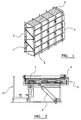
- Figure 1 shows an exemplary panel suitable for production in the machine according to the invention.
- the panel comprises a plurality of truss elements 1 having a zig-zag form, with tie wires 2 extending along the length of the truss, each tie wire being welded adjacent an apex of the zig-zag form. In between the truss elements strips of insulating 3 material are located.
- the panel is formed by welding further tie wires 4 perpendicular to the first tie wires on both sides of the panel.
- a typical building panel constructed according the invention comprises a plurality of alternating truss elements and strips of insulating material with a truss element at each end of the panel.
- the panel assembly area comprises an assembly table 5 which can be tilted between horizontal and vertical positions by a pneumatic cylinder 6.
- the table 5 has a first load bearing surface provided by a plurality of slats 7 mounted on a second load bearing surface, which slats 7 extend along the table 5 transverse and perpendicular to the plane in which the table 5 tilts.
- the table transverse to the slats 7 is provided with a datum 8 for the bottom face of the panel frame and the front face of the panel frame. This is due to the panel size can be 1m to 1.5m, no matter what height the panel is the bottom part of the panel will always be the same. The same applies to the length of 1m to 3.6m as the front of the panel will always be the same)
- truss elements of a building panel are slotted into the gaps between the slats 7, and strips of insulating material are slotted in between the truss elements.
- the datum is used to ensure that the ends of each truss and strip of insulating material are aligned with one another.
- the distance between the first and second load bearing surface determines the location height of the insulation. Typically, this will means that the centreline of the truss element and the strip of insulating material will co-incide, although for certain panels this is not the case.
- the panel is then lightly compressed to hold the truss elements and insulation in place and the table is then tilted into a vertical position by the pneumatic cylinder 6. The panel is then removed from the table and placed onto a panel trolley.
- the trolley 11 is then moved so as to present the loosely assembled panel to an alignment mechanism.
- the alignment mechanism comprises two groups of eight banks of rollers 10 arranged as four spatially separated pairs in two planes. The two planes are separated by a distance equivalent to the width of the panel to be produced.
- Each bank of rollers itself comprises a plurality of aligned rollers.
- the first set of rollers 10 ensures that the truss elements and insulation are in the desired position.
- the second set of rollers 12, comprising three rollers, is located in plane perpendicular to the first set of rollers, compresses the panel frame.
- the position of each roller is adjustable to allow for panels of different height, width, length, wire type, insulation type and in case the centreline of the insulation needs to be off set from the centreline of the truss.
- the trolley does not go through the machine, only the panel and the panel frame. The trolley is used to transport the panel and panel frame into the machine where it is then indexed through the machine and the panel frame are pulled off of the trolley. At the other end of the machine, the complete panel is indexed onto a second trolley. The panel is removed and the trolley is then used to transport the empty panel frame back to the assembly table where a new panel is assembled.
- the top beam and its compressing rollers are adjustable in the vertical plane to suit the panel height (e.g. 1 to 1.5m).
- the compression rollers are attached via a vertical member to an upper beam 13, which upper beam can be translated in the vertical plane via a lockable screw mechanism 14 fixed to the frame of the apparatus.
- the first set of rollers at the point where the trusses enter the machine align the insulation centreline with the truss centreline.
- These rollers are supported on a vertical member 15, the position of which in the horizontal plane can be adjusted via a second set of lockable screw means 16.
- the mechanisms are in two halves, one for each side of the machine. Each one can be independently adjusted.
- the adjustment at the front of the machine again is in two halves, one for each set of welding apparatus again by means of a lockable screw means.
- the four previously mentioned items are adjustable to allow for the different panel widths, wire thickness and in case the insulation is offset from the centreline of the trass.
- the trusses are held in position by the vertical compression force.
- the trusses are first laid in the correct position on the assembly table and lightly clamped. As the loose panel goes through the rollers the insulation is aligned with the truss and the panel is gradually compressed further to ensure that the insulation and truss do not move. If one group of rollers were to move in a positive direction and the other in a negative direction, the insulation would be offset to that of the truss.
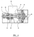
- the indexing mechanism for moving the panel through the machine comprises a plurality of pneumatic cylinders 17 spaced substantially equidistantly from one another along the underside of the bottom rail.
- Each cylinder has a pin 18 attached to its free end.
- the pin engages the underside of the panel frame, which is serrated and urges the panel through the machine.
- the pin pivots out of position and enables the cylinder to return to its start position without fouling on the frame.
- Each cylinder is synchronised with the others to ensure a smooth progression through the machine (and to allow for the variety of panel lengths).
- the constituent elements of the panel are fed to a welding station, in which a wire is welded to or adjacent to the apices of the truss elements.
- Wire is fed to the welding station from coils, a typical example would be 500 kg.
- the wire is fed through a series of guiding pulleys located towards the upper side of the machine, and then through vertical and horizontal wire straighteners below the guiding pulleys into a gripping mechanism 19, which is located on the inside face of the rodless cylinders to hold the wire in position.
- the motion of the gripper is controlled by a rodless cylinder 20.
- the strength of the cylinders which are adapted to move up and down, draws the wire through and over the pulley system and off of the formers.
- a set of grippers holds the end piece of wire.
- the wire grippers then return to the top position ready to repeat the process. Once in position the welding heads are actuated to weld the wire to truss elements.
- the welding apparatus comprises four 100KVA transformers 21, each of which is adapted to power up to 25% of the weld heads.
- Each transformer has 4 settings. They can be set to 25%, 50%, 75% or 100% of its available power.
- Current travels from the transformer into a first bus bar and then to the weld head, through the weld materials into the weld fingers and into a second bus bar and the back to the transformer.
- a cooler unit 22 is provided which provides coolant to the transformers, weld control units and the weld heads to help maintain a constant temperature and reduce the chances of any manufacturing errors which might occur due to heat expansion.
- trimmers located at the top and bottom of the panel.
- the trimmers are pneumatically powered and are adjustable so as to cope with the variety of the panel sizes that the machine can produce.
- the trimmers are fixed to the different adjustable sections. If the front, right hand side is moved out, then the front, right hand section including the rodless cylinder, weld fingers, wire straightners, trimmers (top and bottom), etc. would also move out.
- the machine is provided with a control system to control the automated cycles of the machine.
- the control system can be used to control the welding station and in particular, the output of the transformers may be adjusted depending on the panel to be produced. Depending on the parameters used not all of the welding heads will be required and so some weld heads can be turned off. Each weld head cylinder can be independently isolated to match the required panel height and type to be produced.
- the machine is suitable for fabricating panels in a variety of lengths, heights and widths, e.g. 75mm to 150mm in 25mm increments (widths), 1000mm to 1500mm in 50mm increments (height) and 1000mm to 3600mm in 50mm increments (length).
- the panel has generally been described as having an insulated core, for certain applications this may be dispensed with.
Landscapes
- Engineering & Computer Science (AREA)
- Mechanical Engineering (AREA)
- Architecture (AREA)
- Civil Engineering (AREA)
- Optics & Photonics (AREA)
- Physics & Mathematics (AREA)
- Manufacturing & Machinery (AREA)
- Structural Engineering (AREA)
- Automatic Assembly (AREA)
- Sewing Machines And Sewing (AREA)
- Butt Welding And Welding Of Specific Article (AREA)
- Transition And Organic Metals Composition Catalysts For Addition Polymerization (AREA)
- Control Of Motors That Do Not Use Commutators (AREA)
- Management, Administration, Business Operations System, And Electronic Commerce (AREA)
Claims (9)
- Vorrichtung für die Herstellung eines Bauelements, das mehrere Gitterträgerelemente (1) umfasst, wobei die Vorrichtung Folgendes umfasst; einen Ausrichtmechanismus, der so ausgelegt ist, dass er die Gitterträgerelemente (1) in Bezug aufeinander ausrichtet, einen Rastmechanismus, mit dem das Bauelement durch die Vorrichtung bewegt werden kann, eine Schweißstation, die so ausgelegt ist, dass sie einen Draht (4) so an die oder neben den Spitzen der Gitterträgerelemente (1) anschweißt, dass ein Element entsteht, und eine Schneidvorrichtung, mit der überflüssiger Draht von dem Element entfernt werden kann, dadurch gekennzeichnet, dass der Ausrichtmechanismus mehrere Rollen (10, 12) umfasst, die in zwei Reihen auf zwei Ebenen angeordnet sind, die im Wesentlichen senkrecht zueinander verlaufen, wobei die Position einer ersten Reihe von Rollen (10), die zwei Gruppen räumlich voneinander getrennter Rollen umfasst, deren Positionen zum Ausrichten der Gitterträgerelemente (1) in einer horizontalen Ebene verstellbar sind, und die Position einer zweiten Reihe von Rollen (12) zum Komprimieren des Elements in einer vertikalen Ebene verstellbar ist.
- Vorrichtung nach Anspruch 1, bei der der Ausrichtmechanismus mehrere räumlich voneinander getrennte Mehrfach-Rollen (10, 12) auf drei Ebenen umfasst.
- Vorrichtung nach Anspruch 2, bei der der Ausrichtmechanismus mehrere räumlich voneinander getrennte Rollenpaare (10, 12) auf drei Ebenen umfasst.
- Vorrichtung nach einem der Ansprüche 1 bis 3, bei der der Rastmechanismus mehrere räumlich voneinander getrennte Zylinder (17) umfasst, wobei jeder Zylinder einen Stift (18) aufweist, der an seinem freien Ende angebracht ist, wobei der Stift (18) so ausgelegt ist, dass er im Gebrauch in das Element eingreift, und der Hub des Zylinders dadurch das Element durch die Vorrichtung schiebt.
- Vorrichtung nach Anspruch 4, bei der der Stift (18) am Ende des Hubs aus der Position schwenkt, damit der Zylinder (17) in eine Ausgangsposition zurückkehren kann.
- Vorrichtung nach einem der Ansprüche 1 bis 5, bei der die Schweißstation einen Greifmechanismus (19) umfasst, der so ausgelegt ist, dass er Draht von einer Drahtspule in eine Position neben den Gitterträgerelementen (1) abzieht, so dass der Draht von einem Schweißkopf an die Gitterträgerelemente angeschweißt werden kann, wodurch das Bauelement gebildet wird.
- Vorrichtung nach einem der Ansprüche 1 bis 6, bei der der Schweißkopf, die Transformatoren (21) der Schweißstation und die Steuereinheiten mit Kühlmittel versorgt werden, um sicherzustellen, dass diese eine im Wesentlichen konstante Temperatur beibehalten.
- Vorrichtung nach einem der Ansprüche 1 bis 7, bei der sich zwischen nebeneinander liegenden Gitterträgerelementen (1) Isoliermaterial (3) befindet und die Rollen (10, 12) des Ausrichtmechanismus das Isoliermaterial (3) und die Gitterträgerelemente (1) komprimieren, wodurch sie sicherstellen, dass das Isoliermaterial (3) und die Gitterträgerelemente (1) ausgerichtet werden.
- Vorrichtung nach Anspruch 8, bei der sich eine erste Gruppe und eine zweite Gruppe von Rollen (10) in entgegengesetzter Richtung bewegen lassen, so dass das Isoliermaterial (3) außerhalb der Mitte der Gitterträgerelemente (1) ausgerichtet wird.
Applications Claiming Priority (3)
| Application Number | Priority Date | Filing Date | Title |
|---|---|---|---|
| GB9926773 | 1999-11-12 | ||
| GB9926773A GB2356169B (en) | 1999-11-12 | 1999-11-12 | Multi width panel fabricating machine |
| PCT/GB2000/004337 WO2001034338A1 (en) | 1999-11-12 | 2000-11-13 | Multi width panel fabricating machine |
Publications (2)
| Publication Number | Publication Date |
|---|---|
| EP1237676A1 EP1237676A1 (de) | 2002-09-11 |
| EP1237676B1 true EP1237676B1 (de) | 2008-01-09 |
Family
ID=10864397
Family Applications (1)
| Application Number | Title | Priority Date | Filing Date |
|---|---|---|---|
| EP00974695A Expired - Lifetime EP1237676B1 (de) | 1999-11-12 | 2000-11-13 | Vorrichtung zum herstellen von multibreitplatten |
Country Status (6)
| Country | Link |
|---|---|
| EP (1) | EP1237676B1 (de) |
| AT (1) | ATE383220T1 (de) |
| AU (1) | AU1291101A (de) |
| DE (1) | DE60037749D1 (de) |
| GB (1) | GB2356169B (de) |
| WO (1) | WO2001034338A1 (de) |
Families Citing this family (2)
| Publication number | Priority date | Publication date | Assignee | Title |
|---|---|---|---|---|
| ITUD20090049A1 (it) * | 2009-02-25 | 2010-08-26 | Tecnodinamica S R L | Apparecchiatura per la realizzazione di pannelli prefabbricati e relativo procedimento |
| FR2986815B1 (fr) * | 2012-02-13 | 2014-12-19 | Micro Controle Spectra Physics | Dispositif et systeme d'alignement et de maintien en position de poutres. |
Family Cites Families (5)
| Publication number | Priority date | Publication date | Assignee | Title |
|---|---|---|---|---|
| US2390174A (en) * | 1943-01-01 | 1945-12-04 | George R Roemer | Continuous manufacture of welded wire mesh |
| BE885596Q (fr) * | 1972-03-22 | 1981-02-02 | Cs & M Inc | Procede de fabrication de matrices |
| US4340802A (en) * | 1977-12-05 | 1982-07-20 | Covington Brothers Technologies | Method and apparatus for welding |
| MX155833A (es) * | 1982-05-14 | 1988-05-10 | Martin Monzon Indave | Instalacion para la fabricacion en proceso continuo de paneles mixtos para la construccion de edificios |
| DE4402869A1 (de) * | 1994-01-31 | 1995-08-03 | Se Hong Ahn | Maschine zur Herstellung von Bauplatten |
-
1999
- 1999-11-12 GB GB9926773A patent/GB2356169B/en not_active Expired - Fee Related
-
2000
- 2000-11-13 AT AT00974695T patent/ATE383220T1/de not_active IP Right Cessation
- 2000-11-13 AU AU12911/01A patent/AU1291101A/en not_active Abandoned
- 2000-11-13 WO PCT/GB2000/004337 patent/WO2001034338A1/en not_active Ceased
- 2000-11-13 EP EP00974695A patent/EP1237676B1/de not_active Expired - Lifetime
- 2000-11-13 DE DE60037749T patent/DE60037749D1/de not_active Expired - Lifetime
Also Published As
| Publication number | Publication date |
|---|---|
| GB9926773D0 (en) | 2000-01-12 |
| AU1291101A (en) | 2001-06-06 |
| EP1237676A1 (de) | 2002-09-11 |
| DE60037749D1 (de) | 2008-02-21 |
| WO2001034338A1 (en) | 2001-05-17 |
| ATE383220T1 (de) | 2008-01-15 |
| GB2356169B (en) | 2003-10-08 |
| GB2356169A (en) | 2001-05-16 |
Similar Documents
| Publication | Publication Date | Title |
|---|---|---|
| EP2279807B1 (de) | Maschine mit variabler linearer Geometrie zur kontinuierlichen Herstellung von rechteckigen Rohren | |
| CN108637703A (zh) | 一种钢格板焊接流水总线及焊接方法 | |
| KR102358140B1 (ko) | 철망 절곡장치 | |
| KR102460169B1 (ko) | 다열 구조를 가지는 변압기 철심 제조장치 | |
| CN101218044B (zh) | 滚轧成形机及滚轧成形方法 | |
| EP1152846B1 (de) | Maschine zur herstellung von trägern | |
| EP1237676B1 (de) | Vorrichtung zum herstellen von multibreitplatten | |
| CN205335067U (zh) | 一种变压器e型铁心全自动叠装生产线 | |
| CN100415405C (zh) | 制造格构梁的方法和设备 | |
| CN107695246A (zh) | 一种立式漆包线定型机 | |
| CN113415639B (zh) | 一种龙骨自动小捆堆垛机 | |
| JPS6133727A (ja) | 三次元金属構造体の製造方法及び装置 | |
| WO1995005906A1 (en) | Method and machines for the production of product consisting of two parallel steel wire-meshes and intermediate panel of insulating material | |
| US6422271B1 (en) | Apparatus and method for making clamp rings | |
| CN205852268U (zh) | 角钢焊接和矫直系统、及角钢夹送辊道装置 | |
| US20030106400A1 (en) | Die assembly | |
| US5115703A (en) | Method of cutting strips for wound core | |
| CN215395665U (zh) | 一种保温板切割装置 | |
| CN115458316B (zh) | 一种全自动变压器叠片机 | |
| KR100352789B1 (ko) | 레이저용접용 판재 고정장치 | |
| CN112271073B (zh) | 一种用于变压器铁芯的自动叠片设备 | |
| EP3753644B1 (de) | Rollformmaschine und verfahren zur rollformung | |
| EA005848B1 (ru) | Способ изготовления решетчатых конструкций и устройство для его реализации | |
| CN117161258B (zh) | 一种用于电力施工的电缆线切割装置 | |
| KR200371667Y1 (ko) | 변압기코어용 강판 자동적재장치 |
Legal Events
| Date | Code | Title | Description |
|---|---|---|---|
| PUAI | Public reference made under article 153(3) epc to a published international application that has entered the european phase |
Free format text: ORIGINAL CODE: 0009012 |
|
| 17P | Request for examination filed |
Effective date: 20020612 |
|
| AK | Designated contracting states |
Kind code of ref document: A1 Designated state(s): AT BE CH CY DE DK ES FI FR GB GR IE IT LI LU MC NL PT SE TR |
|
| AX | Request for extension of the european patent |
Free format text: AL;LT;LV;MK;RO;SI |
|
| 17Q | First examination report despatched |
Effective date: 20050303 |
|
| GRAP | Despatch of communication of intention to grant a patent |
Free format text: ORIGINAL CODE: EPIDOSNIGR1 |
|
| GRAS | Grant fee paid |
Free format text: ORIGINAL CODE: EPIDOSNIGR3 |
|
| GRAA | (expected) grant |
Free format text: ORIGINAL CODE: 0009210 |
|
| AK | Designated contracting states |
Kind code of ref document: B1 Designated state(s): AT BE CH CY DE DK ES FI FR GB GR IE IT LI LU MC NL PT SE TR |
|
| REG | Reference to a national code |
Ref country code: GB Ref legal event code: FG4D |
|
| REG | Reference to a national code |
Ref country code: CH Ref legal event code: EP |
|
| REG | Reference to a national code |
Ref country code: IE Ref legal event code: FG4D |
|
| REF | Corresponds to: |
Ref document number: 60037749 Country of ref document: DE Date of ref document: 20080221 Kind code of ref document: P |
|
| PG25 | Lapsed in a contracting state [announced via postgrant information from national office to epo] |
Ref country code: NL Free format text: LAPSE BECAUSE OF FAILURE TO SUBMIT A TRANSLATION OF THE DESCRIPTION OR TO PAY THE FEE WITHIN THE PRESCRIBED TIME-LIMIT Effective date: 20080109 |
|
| NLV1 | Nl: lapsed or annulled due to failure to fulfill the requirements of art. 29p and 29m of the patents act | ||
| PG25 | Lapsed in a contracting state [announced via postgrant information from national office to epo] |
Ref country code: FI Free format text: LAPSE BECAUSE OF FAILURE TO SUBMIT A TRANSLATION OF THE DESCRIPTION OR TO PAY THE FEE WITHIN THE PRESCRIBED TIME-LIMIT Effective date: 20080109 Ref country code: CH Free format text: LAPSE BECAUSE OF FAILURE TO SUBMIT A TRANSLATION OF THE DESCRIPTION OR TO PAY THE FEE WITHIN THE PRESCRIBED TIME-LIMIT Effective date: 20080109 Ref country code: LI Free format text: LAPSE BECAUSE OF FAILURE TO SUBMIT A TRANSLATION OF THE DESCRIPTION OR TO PAY THE FEE WITHIN THE PRESCRIBED TIME-LIMIT Effective date: 20080109 Ref country code: ES Free format text: LAPSE BECAUSE OF FAILURE TO SUBMIT A TRANSLATION OF THE DESCRIPTION OR TO PAY THE FEE WITHIN THE PRESCRIBED TIME-LIMIT Effective date: 20080420 |
|
| REG | Reference to a national code |
Ref country code: CH Ref legal event code: PL |
|
| PG25 | Lapsed in a contracting state [announced via postgrant information from national office to epo] |
Ref country code: AT Free format text: LAPSE BECAUSE OF FAILURE TO SUBMIT A TRANSLATION OF THE DESCRIPTION OR TO PAY THE FEE WITHIN THE PRESCRIBED TIME-LIMIT Effective date: 20080109 |
|
| PG25 | Lapsed in a contracting state [announced via postgrant information from national office to epo] |
Ref country code: BE Free format text: LAPSE BECAUSE OF FAILURE TO SUBMIT A TRANSLATION OF THE DESCRIPTION OR TO PAY THE FEE WITHIN THE PRESCRIBED TIME-LIMIT Effective date: 20080109 Ref country code: PT Free format text: LAPSE BECAUSE OF FAILURE TO SUBMIT A TRANSLATION OF THE DESCRIPTION OR TO PAY THE FEE WITHIN THE PRESCRIBED TIME-LIMIT Effective date: 20080609 |
|
| EN | Fr: translation not filed | ||
| PG25 | Lapsed in a contracting state [announced via postgrant information from national office to epo] |
Ref country code: DK Free format text: LAPSE BECAUSE OF FAILURE TO SUBMIT A TRANSLATION OF THE DESCRIPTION OR TO PAY THE FEE WITHIN THE PRESCRIBED TIME-LIMIT Effective date: 20080109 Ref country code: SE Free format text: LAPSE BECAUSE OF FAILURE TO SUBMIT A TRANSLATION OF THE DESCRIPTION OR TO PAY THE FEE WITHIN THE PRESCRIBED TIME-LIMIT Effective date: 20080409 |
|
| PLBE | No opposition filed within time limit |
Free format text: ORIGINAL CODE: 0009261 |
|
| STAA | Information on the status of an ep patent application or granted ep patent |
Free format text: STATUS: NO OPPOSITION FILED WITHIN TIME LIMIT |
|
| 26N | No opposition filed |
Effective date: 20081010 |
|
| PG25 | Lapsed in a contracting state [announced via postgrant information from national office to epo] |
Ref country code: DE Free format text: LAPSE BECAUSE OF FAILURE TO SUBMIT A TRANSLATION OF THE DESCRIPTION OR TO PAY THE FEE WITHIN THE PRESCRIBED TIME-LIMIT Effective date: 20080410 |
|
| PG25 | Lapsed in a contracting state [announced via postgrant information from national office to epo] |
Ref country code: FR Free format text: LAPSE BECAUSE OF FAILURE TO SUBMIT A TRANSLATION OF THE DESCRIPTION OR TO PAY THE FEE WITHIN THE PRESCRIBED TIME-LIMIT Effective date: 20081031 |
|
| PG25 | Lapsed in a contracting state [announced via postgrant information from national office to epo] |
Ref country code: MC Free format text: LAPSE BECAUSE OF NON-PAYMENT OF DUE FEES Effective date: 20081130 |
|
| PG25 | Lapsed in a contracting state [announced via postgrant information from national office to epo] |
Ref country code: CY Free format text: LAPSE BECAUSE OF FAILURE TO SUBMIT A TRANSLATION OF THE DESCRIPTION OR TO PAY THE FEE WITHIN THE PRESCRIBED TIME-LIMIT Effective date: 20080109 |
|
| PG25 | Lapsed in a contracting state [announced via postgrant information from national office to epo] |
Ref country code: IT Free format text: LAPSE BECAUSE OF FAILURE TO SUBMIT A TRANSLATION OF THE DESCRIPTION OR TO PAY THE FEE WITHIN THE PRESCRIBED TIME-LIMIT Effective date: 20080109 |
|
| PG25 | Lapsed in a contracting state [announced via postgrant information from national office to epo] |
Ref country code: LU Free format text: LAPSE BECAUSE OF NON-PAYMENT OF DUE FEES Effective date: 20081113 |
|
| PG25 | Lapsed in a contracting state [announced via postgrant information from national office to epo] |
Ref country code: TR Free format text: LAPSE BECAUSE OF FAILURE TO SUBMIT A TRANSLATION OF THE DESCRIPTION OR TO PAY THE FEE WITHIN THE PRESCRIBED TIME-LIMIT Effective date: 20080109 |
|
| PG25 | Lapsed in a contracting state [announced via postgrant information from national office to epo] |
Ref country code: GR Free format text: LAPSE BECAUSE OF FAILURE TO SUBMIT A TRANSLATION OF THE DESCRIPTION OR TO PAY THE FEE WITHIN THE PRESCRIBED TIME-LIMIT Effective date: 20080410 |
|
| PGFP | Annual fee paid to national office [announced via postgrant information from national office to epo] |
Ref country code: GB Payment date: 20181002 Year of fee payment: 19 |
|
| PGFP | Annual fee paid to national office [announced via postgrant information from national office to epo] |
Ref country code: IE Payment date: 20191108 Year of fee payment: 20 |
|
| GBPC | Gb: european patent ceased through non-payment of renewal fee |
Effective date: 20191113 |
|
| PG25 | Lapsed in a contracting state [announced via postgrant information from national office to epo] |
Ref country code: GB Free format text: LAPSE BECAUSE OF NON-PAYMENT OF DUE FEES Effective date: 20191113 |
|
| REG | Reference to a national code |
Ref country code: IE Ref legal event code: MK9A |
|
| PG25 | Lapsed in a contracting state [announced via postgrant information from national office to epo] |
Ref country code: IE Free format text: LAPSE BECAUSE OF EXPIRATION OF PROTECTION Effective date: 20201113 |