EP1237317A2 - Verfahren und System zum Wechsel von Übertragungsmodus - Google Patents
Verfahren und System zum Wechsel von Übertragungsmodus Download PDFInfo
- Publication number
- EP1237317A2 EP1237317A2 EP02004249A EP02004249A EP1237317A2 EP 1237317 A2 EP1237317 A2 EP 1237317A2 EP 02004249 A EP02004249 A EP 02004249A EP 02004249 A EP02004249 A EP 02004249A EP 1237317 A2 EP1237317 A2 EP 1237317A2
- Authority
- EP
- European Patent Office
- Prior art keywords
- mode
- modulation
- error rate
- block error
- switching
- Prior art date
- Legal status (The legal status is an assumption and is not a legal conclusion. Google has not performed a legal analysis and makes no representation as to the accuracy of the status listed.)
- Withdrawn
Links
- 230000005540 biological transmission Effects 0.000 title claims abstract description 121
- 238000000034 method Methods 0.000 title claims description 31
- 238000010295 mobile communication Methods 0.000 claims abstract description 35
- 238000001514 detection method Methods 0.000 claims description 5
- 238000012545 processing Methods 0.000 claims description 4
- 238000010586 diagram Methods 0.000 description 36
- 238000005259 measurement Methods 0.000 description 8
- 238000012544 monitoring process Methods 0.000 description 4
- 238000005516 engineering process Methods 0.000 description 3
- 230000010363 phase shift Effects 0.000 description 3
- 238000004904 shortening Methods 0.000 description 2
- 230000001413 cellular effect Effects 0.000 description 1
- 238000004891 communication Methods 0.000 description 1
- 125000004122 cyclic group Chemical group 0.000 description 1
- 230000000694 effects Effects 0.000 description 1
- 238000012986 modification Methods 0.000 description 1
- 230000004048 modification Effects 0.000 description 1
- 238000005457 optimization Methods 0.000 description 1
Images


Classifications
-
- H—ELECTRICITY
- H04—ELECTRIC COMMUNICATION TECHNIQUE
- H04W—WIRELESS COMMUNICATION NETWORKS
- H04W88/00—Devices specially adapted for wireless communication networks, e.g. terminals, base stations or access point devices
- H04W88/08—Access point devices
- H04W88/10—Access point devices adapted for operation in multiple networks, e.g. multi-mode access points
-
- H—ELECTRICITY
- H04—ELECTRIC COMMUNICATION TECHNIQUE
- H04L—TRANSMISSION OF DIGITAL INFORMATION, e.g. TELEGRAPHIC COMMUNICATION
- H04L1/00—Arrangements for detecting or preventing errors in the information received
- H04L1/20—Arrangements for detecting or preventing errors in the information received using signal quality detector
-
- H—ELECTRICITY
- H04—ELECTRIC COMMUNICATION TECHNIQUE
- H04L—TRANSMISSION OF DIGITAL INFORMATION, e.g. TELEGRAPHIC COMMUNICATION
- H04L1/00—Arrangements for detecting or preventing errors in the information received
- H04L1/0001—Systems modifying transmission characteristics according to link quality, e.g. power backoff
- H04L1/0002—Systems modifying transmission characteristics according to link quality, e.g. power backoff by adapting the transmission rate
- H04L1/0003—Systems modifying transmission characteristics according to link quality, e.g. power backoff by adapting the transmission rate by switching between different modulation schemes
-
- H—ELECTRICITY
- H04—ELECTRIC COMMUNICATION TECHNIQUE
- H04L—TRANSMISSION OF DIGITAL INFORMATION, e.g. TELEGRAPHIC COMMUNICATION
- H04L1/00—Arrangements for detecting or preventing errors in the information received
- H04L1/0001—Systems modifying transmission characteristics according to link quality, e.g. power backoff
- H04L1/0009—Systems modifying transmission characteristics according to link quality, e.g. power backoff by adapting the channel coding
-
- H—ELECTRICITY
- H04—ELECTRIC COMMUNICATION TECHNIQUE
- H04L—TRANSMISSION OF DIGITAL INFORMATION, e.g. TELEGRAPHIC COMMUNICATION
- H04L1/00—Arrangements for detecting or preventing errors in the information received
- H04L1/0001—Systems modifying transmission characteristics according to link quality, e.g. power backoff
- H04L1/0015—Systems modifying transmission characteristics according to link quality, e.g. power backoff characterised by the adaptation strategy
-
- H—ELECTRICITY
- H04—ELECTRIC COMMUNICATION TECHNIQUE
- H04L—TRANSMISSION OF DIGITAL INFORMATION, e.g. TELEGRAPHIC COMMUNICATION
- H04L1/00—Arrangements for detecting or preventing errors in the information received
- H04L1/0001—Systems modifying transmission characteristics according to link quality, e.g. power backoff
- H04L1/0033—Systems modifying transmission characteristics according to link quality, e.g. power backoff arrangements specific to the transmitter
- H04L1/0034—Systems modifying transmission characteristics according to link quality, e.g. power backoff arrangements specific to the transmitter where the transmitter decides based on inferences, e.g. use of implicit signalling
-
- H—ELECTRICITY
- H04—ELECTRIC COMMUNICATION TECHNIQUE
- H04L—TRANSMISSION OF DIGITAL INFORMATION, e.g. TELEGRAPHIC COMMUNICATION
- H04L1/00—Arrangements for detecting or preventing errors in the information received
- H04L1/12—Arrangements for detecting or preventing errors in the information received by using return channel
- H04L1/16—Arrangements for detecting or preventing errors in the information received by using return channel in which the return channel carries supervisory signals, e.g. repetition request signals
- H04L1/18—Automatic repetition systems, e.g. Van Duuren systems
Definitions
- the present invention relates to a mobile communication system and a transmission mode switching method used therefor as well as a recording medium having a program of the method recorded therein and, in particular, to a modulation/coding mode switching method in a system using an HS-PDSCH (High Speed-Physical Downlink Shared Channel).
- HS-PDSCH High Speed-Physical Downlink Shared Channel
- a mobile terminal such as a cellular phone
- multimedia for handling still images with a large amount of data, short animations or the like and a large-capacity and high-speed data transmission method is required accordingly.
- a PDSCH system that makes only a transmission speed in downlink (direction form a base station to a mobile station) high, an HS-PDSCH (High Speed-Physical Downlink Shared Channel) system, or the like.
- HS-PDSCH High Speed-Physical Downlink Shared Channel
- any one of a plurality of modulation/coding modes such as a QPSK (Quadrature Phase Shift Keying) that is capable of transmitting two bits (four values) by one modulation, a 16QAM (16 Quadrature Amplitude Modulation) that is capable of transmitting four bits (sixteen values) by one modulation and a 64QAM (64 Quadrature Amplitude Modulation) that is capable of transmitting six bits (sixty-four values) by one modulation.
- QPSK Quadratture Phase Shift Keying
- 16QAM 16 Quadrature Amplitude Modulation
- 64QAM 64 Quadrature Amplitude Modulation
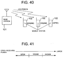
- FIG. 40 An example of selecting one of the modulation/coding modes is shown in FIG. 40.
- the modulation/coding mode is selected such that the closer a mobile station 102 is to a base station 101 in distance the faster the transmission is. That is, the base station 101 selects the modulation/coding modes of the 64QAM, the 16QAM and the QPSK in the order of closeness to the mobile station 102.
- a method of selecting one of the above-described modulation/coding modes of the 64QAM, the 16QAM and the QPSK conventionally, there is a method of determining in advance a range of a receiving quality (Ec/Io (energy per one chip/interference wave power per unit frequency)) of a common pilot signal (CPICH: Common Pilot Channel) that is forwarded from a base station to a mobile station and uses respective modulation/coding modes and selecting a modulation/coding mode according to a receiving quality of a common pilot signal (hereinafter referred to as a first prior art).
- Ec/Io energy per one chip/interference wave power per unit frequency
- CPICH Common Pilot Channel
- the mobile station measures a receiving quality of a common pilot signal from the base station to inform the base station of the receiving quality.
- a modulation/coding mode is selected by the base station according to a receiving quality of a common pilot signal informed by the mobile station. For example, as shown in FIG. 41, the base station selects the modulation/coding modes of the 64QAM, the 16QAM and the QPSK in the order of excellence of a receiving quality of a common pilot signal informed by the mobile station.
- the mobile station detects an error of an HS-PDSCH data block from the base station.
- the base station or the mobile station calculates a block error rate of the HS-PDSCH data at a predetermined period set in advance and selects a modulation/coding mode according to the block error rate.
- the base station or the mobile station switches the modulation/coding mode to a low-speed mode if a calculated block error rate is larger than a predetermined block error rate T.
- it is switched from the 16QAM modulation/coding mode to the QPSK modulation/coding mode.
- the base station or the mobile station switches the modulation/coding mode to a high-speed mode if a calculated block error rate is smaller than the predetermined block error rate T. In FIG. 42, it is switched from the QPSK modulation/coding mode to the 16QAM modulation/coding mode.
- the optimal mode means a mode with which a data transmission speed becomes maximum among modes that can satisfy a target communication quality (block error rate or the like).
- a transmission power of the HS-PDSCH is changed while keeping a transmission power of a common pilot signal constant
- the base station if the mobile station performs mode selection, it is necessary for the base station to inform the mobile station of information on the change of the transmission power of the HS-PDSCH and the mobile station to select a mode based on the information.
- control information of which the base station informs the mobile station increases and an optimal mode cannot be selected while the base station sending the control information.
- the base station performs mode selection it is necessary for the base station to change a threshold value of each mode according to the change of the transmission power of the HS-PDSCH.
- the second prior art also has a problem that selection of an optimal mode is difficult.
- the present invention has been achieved in view of these problems, and it is an object of the present invention to provide a mobile communication system that is capable of easily carrying out selection of an optimal modulation/coding mode and a modulation/coding mode switching method used therefor as well as a recording medium having program of the same method recorded therein.
- a mobile communication system is a mobile communication system capable of selecting any one of a plurality of modulation/coding modes used for data transmission of a unit of block between a base station controlled by a base station control apparatus and a mobile station, which is provided with detecting means that is provided in the mobile station and detects occurrence of a receiving error of a unit of block in the data transmission and switching selecting means for switching the modulation/coding modes based on the occurrence of the receiving error to be detected by the detecting means.
- a modulation/coding mode switching method is a modulation/coding mode switching method capable of selecting any one of a plurality of modulation/coding modes used for data transmission of a unit of block between a base station controlled by a base station control apparatus and a mobile station, which is provided with a first step of detecting occurrence of a receiving error of a unit of block in the data transmission in the mobile station and a second step of performing switching of the modulation/coding modes based on the occurrence of the receiving error to be detected in the first step.
- a recording medium having recorded therein a program of a modulation/coding mode switching method is a recording medium having program of a modulation/coding mode switching method of a mobile communication system capable of selecting any one of a plurality of modulation/coding mode used for data transmission of a unit of block between a base station controlled by a base station control apparatus and a mobile station, the program causes a computer to execute processing for detecting occurrence of a receiving error of a unit of block in the data transmission in the mobile station and processing for performing switching of the modulation/coding mode based on the occurrence of the receiving error to be detected.
- the mobile communication system of the present invention is the mobile communication system capable of selecting any one of the plurality of modulation/coding modes, which performs switching of the modulation/coding modes based on occurrence of a receiving error.
- the mobile station when the base station sends an information block to the mobile station, the mobile station receives the information block and, if the receipt of the information block contains an error, informs the base station that it has failed to receive the information block.
- the base station switches the modulation/coding mode to a mode of lower transmission rate (hereinafter denoted as "a slower mode") than a current mode when failures of receiving the information block have reached a predetermined number of times (one or more).
- the base station switches the modulation/coding mode to a mode of higher transmission rate (hereinafter denoted as "a faster mode") than a current mode when successes of receiving the information block have reached another predetermined number of times (larger than the above-described predetermined number of times).
- the switching to a faster mode may be performed when a receiving error rate within a predetermined length of time has become smaller than a predetermined value.
- request/determination of switching of the modulation/coding modes based on a receiving error may be carried out in the mobile station or the base station control apparatus instead of the base station.
- the switching of the modulation/coding modes is carried out based on occurrence of a receiving error, and conditions for switching the modulation/coding mode to a mode faster than a current mode and conditions for switching the modulation/coding mode to a mode slower than a current mode are made different.
- the base station switches the modulation/coding mode to a slower mode if the mobile station has failed to receive information block and to a faster mode if the mobile station has succeeded in receiving information block continuously for a predetermined number of blocks Ns (or predetermined time Ts) or more.
- Ns or predetermined time Ts
- the time for condition for switching the modulation/coding mode to a faster mode is made shorter than the time for the condition for switching to a slower mode.
- the rate of shortening the time is made equal to a ratio of data transmission speeds.
- the modulation/coding mode is switched to a slower mode in response to occurrence of an error of one block, whereby it becomes possible to promptly switch the modulation/coding mode to a slower mode when conditions of a transmission path are deteriorated.
- a target block error rate is satisfied, it becomes possible to immediately switch the modulation/coding mode to a faster mode.
- the modulation/coding mode is switched to a slower mode when a block error rate in a first predetermined number of blocks N1 (or first predetermined time T1) is larger than a first predetermined block error rate R1, switched to a faster mode when a block error rate in a second predetermined number of blocks N2 (or second predetermined time T2) is smaller than a second predetermined block error rate R2, and switched to a slower mode when the block error rate in the second predetermined number of blocks N2 (or second predetermined time T2) is equal to or larger than a third predetermined block error rate R3.
- the time for the condition for switching the modulation/coding mode to a faster mode is made shorter than the time for the condition for switching to a slower mode.
- the rate of shortening the time is made equal to a ratio of data transmission speeds.
- the first predetermined number of blocks N1 and the second predetermined number of blocks N2 (or the first predetermined time T1 and the second predetermined time T2), the fist predetermined block error rate R1, the second predetermined block error rate R2 and the third predetermined block error rate R3 are determined according to a target block error rate.
- the modulation/coding mode is switched to a slower mode with the first predetermined number of blocks N1 that is smaller than the other number of blocks in response to increase of the block error rate, it becomes possible to promptly switch the modulation/coding mode to a slower mode when conditions of a transmission path are deteriorated.
- the modulation/coding mode is switched to a faster mode with the second predetermined number of blocks N2 larger than the first predetermined number of blocks N1 in response to decrease of the block error rate, it becomes possible to satisfy a target block error rate.
- the block error rate is monitored at a long period, it becomes possible to reduce unnecessary switching operations due to occurrence of block errors.
- FIG. 1 is a block diagram showing a configuration of a mobile communication system according to an embodiment mode of the present invention.
- the mobile communication system according to the embodiment mode of the present invention consists of a base station 1, a mobile station 2 and a base station control apparatus (e.g., RNC (Radio Network Controller)) 3.
- RNC Radio Network Controller
- the base station 1 divides data of an HS-PDSCH (High Speed-Physical Downlink Shared Channel) into blocks and sends them to the mobile station 2.
- a CRC (Cyclic Redundancy Check) code error detection code
- the mobile station 2 determines existence or nonexistence of a receiving error of each data block using the CRC code and informs the base station 1 of a result of the determination.
- any one of the base station 1, the mobile station 2 and the base station control apparatus 3 may perform determination of switching of the above-described modulation/coding modes.
- the base station 1 or the base station control apparatus 3 determines switching of the modulation/coding modes, it uses a DPCH (Dedicated Physical Channel) of down link (DL) to inform the mobile station 2 of the switching.
- a DPCH Dedicated Physical Channel
- DL down link
- UL up link
- the base station 1 switches the modulation/coding modes at predetermined timing after informing the above-described mode switching.
- FIG. 2 is a block diagram showing a configuration of the base station 1 according to a first embodiment of the present invention.
- the base station 1 comprises an antenna 11, a duplexer (DUP) 12, a receiving portion 13, a user information/control information separating portion 14, a modulation/coding mode switching selecting portion 15, a control portion 16, a modulation/coding portion 17, a composing portion 18, a transmitting portion 19 and a recording medium 20.
- DUP duplexer
- the receiving portion 13 forwards a signal (DPCH(UL) or the like) received via the antenna 11 and the duplexer 12 to the user information/control information separating portion 14.
- the user information/control information separating portion 14 separates a received signal from the receiving portion 13 into user information (a voice signal, an image signal or the like) and control information. Then, the user information/control information separating portion 14 forwards the user information to the above-described call control portion, voice output portion and display portion of the base station 1 and forwards the control information to the modulation/coding mode switching selection portion 15 and the control portion 16.
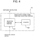
- the modulation/coding mode switching selecting portion 15 executes a program stored in the recording medium 20, thereby monitoring a receiving error notice from a not-shown mobile station, and, upon receiving a receiving error notice, forwards an instruction to switch the modulation/coding mode to a mode slower than a current modulation/coding mode to the control portion 16 and the modulation/coding portion 17, respectively.
- the modulation/coding mode switching selecting portion 15 does not receive a receiving error notice continuously for a predetermined number of blocks Ns after receiving a receiving error notice, it forwards an instruction to switch the modulation/coding mode to a mode faster than a current modulation/coding mode to the control portion 16 and the modulation/coding portion 17, respectively.
- the control portion 16 executes a program stored in the recording medium 20, thereby generating various control signals based on control information from the user information/control information separating portion 14 and input information from the outside (e.g., control information or the like from a not-shown base station control apparatus) and outputs the controls signals to each portion within the base station 1 to control it. Further, a program executed by each portion of the base station 1 including the control portion 16 is stored in the recording medium 20.
- control portion 16 when mode switching is performed in the modulation/coding portion 17 according to a switching instruction from the modulation/coding mode switching selecting portion 15, the control portion 16 generates control information including information of the mode switching to forward it to the composing portion 18.
- the modulation/coding portion 17 comprises a QPSK (Quadrature Phase Shift Keying) modulation/coding circuit 171, a 16QAM (16 Quadrature Amplitude Modulation) modulation/coding circuit 172 and a 64QAM (64 Quadrature Amplitude Modulation) modulation/coding circuit 173.
- QPSK Quadratture Phase Shift Keying
- 16QAM 16 Quadrature Amplitude Modulation
- 64QAM 64 Quadrature Amplitude Modulation
- the modulation/coding portion 17 responds to a switching instruction from the modulation/coding mode switching selecting portion 15 to switch over to any one of the QPSK modulation/coding circuit 171, the 16QAM modulation/coding circuit 172 and the 64 QAM modulation/coding circuit 173, performs modulation/coding with the circuit switched to and forwards data to the composing portion 18 as HS-PDSCH data.
- the composing portion 18 composes the control information including the information of mode switching from the control portion 16, the HS-PDSCH data from the modulation/coding portion 17, the input signals from the outside such as the call control portion and the voice input portion of the base station 1, or the like, to send the composed data from the antenna 11 as the HS-PDSCH via the transmitting portion 19 and the duplexer 12.
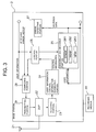
- FIG. 3 is a block diagram showing a configuration of the mobile station 2 according to the first embodiment of the present invention.
- the mobile station 2 comprises an antenna 21, a duplexer (DUP) 22, a receiving portion 23, a user information/control information separating portion 24, acontrol portion 25, a demodulation/decoding portion 26, an error detecting portion 27, a composing portion 28, a transmitting portion 29 and a recording medium 30.
- DUP duplexer
- the receiving portion 23 forwards a signal (CPICH (Common Pilot Channel), DPCH, HS-PDSCH (Physical Downlink Shared Channel)) received via the antenna 21 and the duplexer 22 to the user information/control information separating portion 24.
- CPICH Common Pilot Channel
- DPCH Physical Downlink Shared Channel
- HS-PDSCH Physical Downlink Shared Channel
- the user information/control information separating portion 24 separates a received signal from the receiving portion 23 into user information (a voice signal, an image signal or the like) and control information. Then, the user information/control information separating portion 24 forwards the user information to the demodulation/decoding portion 26, the above-described call control portion, voice output portion and display portion of the mobile station 2, respectively, and forwards the control information to the control portion 25.
- user information a voice signal, an image signal or the like
- the control portion 25 executes a program stored in the recording medium 30, thereby generating various control signals based on control information from the user information/control information separating portion 24 and input information from the outside (e.g., user information or the like from a ten key and a voice input portion) to output them to each portion within the mobile station 2 and control each portion and, at the same time, generating control information to the base station 1 to forward it to the composing portion 28. Further, a program that is executed by each portion of the mobile station 2 including the control portion 25 is stored in the recording medium 30.
- the demodulation/decoding portion 26 comprises a QPSK demodulation/decoding circuit 261, a 16QAM demodulation/decoding circuit 262 and a 64QAM demodulation/decoding circuit 263.
- the demodulation/decoding portion 26 responds to a switching instruction from the control portion 25 to switch over to any one of the QPSK demodulation/decoding circuit 261, the 16QAM demodulation/decoding circuit 262 and the 64QAM demodulation/decoding circuit 263, performs demodulation/decoding with the circuit switched to and outputs HS-PDSCH data to the error detecting portion 27 and each portion within the mobile station 2.
- the error detecting portion 27 determines existence or nonexistence of a receiving error of each data block using a CRC code added to the data and outputs a result of the determination to the composing portion 28.
- the composing portion 28 composes the control information from the control portion 25, the determination result from the error detecting portion 27 and the input signals from the outside such as the call control portion and the voice input portion of the mobile station 2, or the like, to send the composed data from the antenna 21 as the DPCH (UL) and the HS-PDSCH via the transmitting portion 29 and the duplexer 22.
- FIG. 4 is a block diagram showing a configuration of the modulation/coding mode switching selecting portion 15 of FIG. 2.
- the modulation/coding mode switching selecting portion 15 comprises a selection control portion 151 and a counter 152.
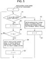
- FIG. 5 is a flow chart showing an operation of modulation/coding mode switching selection by the modulation/coding mode switching selecting portion 15 of FIG. 4. The operation of modulation/coding mode switching selection by the modulation/coding mode switching selecting portion 15 will be described with reference to FIGS. 4 and 5.
- the selection control portion 151 of the modulation/coding mode switching selecting portion 15 switches a modulation/coding mode to a slower mode as a modulation/coding mode for the pertinent mobile station 2 (step S2 in FIG. 5) and clears a counter value C of the counter 152 (C ⁇ 0) (step S3 in FIG. 5).
- the selection control portion 151 increments the counter value C of the counter 152 (C ⁇ C + 1) (step S4 in FIG. 5).
- the selection control portion 151 switches the modulation/coding mode to a faster mode as a modulation/coding mode for the pertinent mobile station 2 (step S6 in FIG. 5) and clears the counter value C of the counter 152 (C ⁇ 0) (step S7 in FIG. 5).
- the selection control portion 151 switches the modulation/coding mode to a slower mode and, if a data block is successfully received continuously for a predetermined number of blocks Ns or more after performing the switching, switches the modulation/coding mode to a faster mode.
- FIG. 6 illustrates a modulation/coding mode switching operation according to the first embodiment of the present invention.
- FIG. 6 shows an operations of switching the modulation/coding mode to a slower QPSK modulation/coding mode in response to occurrence of a block error when the 16QAM modulation/coding mode is selected and, thereafter, switching the modulation/coding mode to the faster 16QAM modulation/coding mode and 64QAM modulation/coding mode in response to nonoccurrence of a block error continuously for the predetermined number of blocks Ns or more.
- the selection control portion 151 controls selection such that 1/(Ne + Ns) is equal to a target block error rate.
- the base station 1 since the base station 1 switches the modulation/coding mode at an error of one block, it can promptly switch the modulation/coding mode to a slower mode when conditions of a transmission path are deteriorated. In addition, when a target block error rate is satisfied, the base station 1 can immediately switch the modulation/coding mode to a faster mode. Thus, the modulation/coding mode can be promptly switched to an optimal mode in the first embodiment of the present invention. In this case, since the predetermined number of blocks Ns is determined according to a target block error rate, the target block error rate can be satisfied.
- FIG. 7 is a block diagram showing a configuration of the modulation/coding mode switching selecting portion 15 according to a second embodiment of the present invention.
- the modulation/coding mode switching selecting portion 15 comprises a selection control portion 151 and a timer 153.
- the second embodiment of the present invention has the same configuration as that of the mobile communication system shown in FIG. 2 and those of the base station 1 according to the first embodiment of the present invention shown in FIG. 1 and the mobile station 2 according to the first embodiment of the present invention shown in FIG. 3, descriptions on them will be omitted.
- FIG. 8 is a flow chart showing an operation of modulation/coding mode switching selection by the modulation/coding mode switching selecting portion 15 of FIG. 7.
- the operation of modulation/coding mode switching selection by the modulation/coding mode switching selecting portion 15 according to the second embodiment of the present invention will be described with reference to FIGS. 7 and 8.
- the selection control portion 151 of the modulation/coding mode switching selecting portion 15 switches the modulation/coding mode to a slower mode as a modulation/coding mode for the pertinent mobile station 2 (step S12 in FIG. 8) and resets the timer 153 (step S13 in FIG. 8).
- step S11 in FIG. 8 If a receiving error notice is not inputted from the mobile station 2 (step S11 in FIG. 8), when a timer value of the timer 153 exceeds the predetermined time Ts (step S14 in FIG. 8), the selection control portion 151 switches the modulation/coding mode to a faster mode as a modulation/coding mode for the pertinent mobile station 2 (step S15 in FIG. 8) and resets the timer 153 (step S16 in FIG. 8).
- the selection control portion 151 switches the modulation/coding mode to a slower mode and, when a data block is successfully received continuously for the predetermined time Ts or more after performing the switching, switches the modulation/coding mode to a faster mode.
- the base station 1 since the base station 1 switches the modulation/coding mode at an error of one block, it can promptly switch the modulation/coding block to a slower mode when conditions of a transmission path are deteriorated. In addition, when a target block error rate is satisfied, the base station 1 can immediately switch the modulation/coding mode to a faster mode. Thus, the modulation/coding mode can be promptly switched to an optimal mode in the second embodiment of the present invention. In this case, if the predetermined time Ts is required for transmission of the predetermined number of blocks Ns, since the predetermined time Ts is determined according to a target block error rate, the target block error rate can be satisfied.
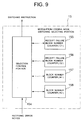
- FIG. 9 is a block diagram showing a configuration of the modulation/coding mode switching selecting portion 15 according to a third embodiment of the present invention.
- the modulation/coding mode switching selecting portion 15 comprises a selection control portion 154, a receipt failure block number counter (C1) 155, a receipt failure block number counter (C2) 156, a block number counter (N1) 157 and a block number counter (N2) 158.
- the third embodiment of the present invention has the same configuration as that of the mobile communication system shown in FIG. 1 and those of the base station 1 according to the first embodiment of the present invention shown in FIG. 2 and the mobile station 2 according to the first embodiment of the present invention shown in FIG. 3, descriptions on them will be omitted.
- FIGS. 10 and 11 are a flow chart showing an operation of modulation/coding switching selection by the modulation/coding mode switching selecting portion 15 of FIG. 9. The operation of modulation/coding mode switching selection by the modulation/coding mode switching selecting portion 15 according to the third embodiment of the present invention will be described with reference to FIGS. 9 to 11.
- the selection control portion 154 of the modulation/coding mode switching selecting portion 15 starts the receipt failure block number counter (C2) 156 (step S22 in FIG. 10). Following the start of the receipt failure block number counter (C2) 156, the selection control portion 154 also starts the block number counter (N2) 158 and increments the block number counter (N2) 158 each time transmission of a data block is performed.
- the selection control portion 154 starts and increments the receipt failure block number counter (C1) 155 (C1 ⁇ C1 + 1) (step S24 in FIG. 10) and, at the same time, increments the receipt failure block number counter (C2) 156 (C2 ⁇ C2 + 1) (step S25 in FIG. 10). Further, following the start of the receipt failure block number counter (C1) 155, the selection control portion 154 also starts the block number counter (N1) 157 and increments the block number counter (N1) 157 each time transmission of a data block is performed.
- the selection control portion 154 switches the modulation/coding mode to a slower mode as a modulation/coding mode for the pertinent mobile station 2 (step S29 in FIG. 10), resets the receipt failure block number counter (C1) 155 (C1 ⁇ 0), resets the receipt failure block number counter (C2) 156 (C2 ⁇ 0) and restarts the receipt failure block number counter (C2) 156 (step S30 in FIG. 10) and returns to step S21.
- step S34 in FIG. 11 resets the receipt failure block number counter (C1) 155 (C1 ⁇ 0), resets the receipt failure block number counter (C2) 156 (C2 ⁇ 0) and restarts the receipt failure block number counter (C2) 156 (step S34 in FIG. 11) and returns to step S21.
- the selection control portion 154 switches the modulation/coding mode to a slower mode as a modulation/coding mode for the pertinent mobile station 2 (step S36 in FIG. 11), resets the receipt failure block number counter (C1) 155 (C1 ⁇ 0), resets the receipt failure block number counter (C2) 156 (C2 ⁇ 0) and restarts the receipt failure block number counter (C2) 156 (step S37 in FIG. 11) and returns to step S21.
- step S35 in FIG. 11 the selection control portion 154 resets the receipt failure block number counter (C2) 156 (C2 ⁇ 0) (step S38 in FIG. 11) and returns to step S21.
- FIG. 12 illustrates a modulation/coding mode switching operation according to the third embodiment of the present invention.
- FIG. 12 shows an operation for switching the modulation/coding mode to a slower QPSK modulation/coding mode if a block error rate is larger than the block error rate R1 set in advance in a predetermined number of blocks N1 since occurrence of a block error when the 16QAM modulation/coding mode is selected.
- FIG. 13 illustrates conditions of switching the modulation/coding modes according to the third embodiment of the present invention. Switching of the modulation/coding modes according to the third embodiment of the present invention will be described with reference to FIGS. 12 and 13.
- the base station 1 Upon receiving a receiving error notice from the mobile station 2, the base station 1 starts the receipt failure block number counter (C1) 155, which counts the number of blocks failed to be received, and counts the number of times of occurrence of a receiving error in the predetermined number of blocks N1 from the block (e.g., ten blocks). As a result, the base station 1 switches the modulation/coding mode to a slower mode if C1/N1 is larger than R1 (e.g., 0.3) and does not perform switching of the modulation/coding mode if C1/N1 is smaller than R1.
- C1/N1 is larger than R1 (e.g., 0.3) and does not perform switching of the modulation/coding mode if C1/N1 is smaller than R1.
- the base station 1 when transmission of a block is started or when the modulation/coding mode has been switched, the base station 1 starts the receipt failure block number counter (C2) 156, which counts the number of blocks failed to be received, and counts the number of times of occurrence of a receiving error in the predetermined number of blocks N2 from the block (e.g., one hundred blocks).
- the base station 1 switches the modulation/coding mode to a faster mode if C2/N2 is smaller than R2 (e.g., 0.1), switches the modulation/coding mode to a slower mode if C2/N2 is larger than R3 (e.g., 0.2) and does not perform switching of the modulation/coding mode if C2/N2 is larger than R2 and smaller than R3.
- C2 receipt failure block number counter
- the predetermined number of blocks N2 is larger than the predetermined number of blocks N1 and, the smaller the predetermined number of blocks N1 the more promptly the modulation/coding mode can be switched in response to increase of a block error rate.
- the base station 1 since the base station 1 switches the modulation/coding mode to a slower mode at the few predetermined number of blocks N1 in response to increase of a block error rate, it can promptly switch the modulation/coding mode to a slower mode when conditions of a transmission path are deteriorated.
- the base station 1 since the base station 1 switches the modulation/coding mode to a faster mode at the predetermined number of blocks N2 that is larger than the predetermined number of blocks N1 in response to decrease of a block error rate, a target block error rate can be satisfied.
- the modulation/coding mode can be promptly switched to an optimal mode in the third embodiment of the present invention.
- unnecessary switching of a mode can be reduced.
- switching to a slower mode is determined according to a plurality of block errors, whereby unnecessary switching of a mode can also be reduced.
- FIG. 14 is a block diagram showing a configuration of the modulation/coding mode switching selecting portion 15 according to a fourth embodiment of the present invention.
- the modulation/coding mode switching selecting portion 15 according to the fourth embodiment of the present invention has the same configuration as that of the modulation/coding mode switching selecting portion 15 according to the third embodiment of the present invention shown in FIG. 9 except that it is provided with a timer (T1) 159 and a timer (T2) 160 instead of the block number counter (N1) 157 and the block number counter (N2) 158 and the identical elements are denoted by the identical reference numerals.
- T1 159 and a timer (T2) 160 instead of the block number counter (N1) 157 and the block number counter (N2) 158 and the identical elements are denoted by the identical reference numerals.
- operations of the identical elements are the same as those in the third embodiment.
- FIGS. 15 and 16 are a flowchart showing an operation of modulation/coding mode switching selection by the modulation/coding mode switching selecting portion 15 of FIG. 14. The operation of modulation/coding mode switching selection by the modulation/coding mode switching selecting portion 15 according to the fourth embodiment of the present invention will be described with reference to FIGS. 14 to 16.
- the selection control portion 154 of the modulation/coding mode switching selecting portion 15 starts the receipt failure block number counter (C2) 156 (step S42 in FIG. 15).
- the selection control portion 154 starts the timer (T2) 160 following the start of the receipt failure block number counter (C2) 156.
- the selection control portion 154 starts and increments the receipt failure block number counter (C1) 155 (C1 ⁇ C1 + 1) (step S44 in FIG. 15) and, at the same time, increments the receipt failure block number counter (C2) 156 (C2 ⁇ C2 + 1) (step S45 in FIG. 15). Further, the selection control portion 154 starts the timer (T1) 159 following the start of the receipt failure block number counter (C1) 155.
- the selection control portion 154 switches the modulation/coding mode to a slower mode as a modulation/coding mode for the pertinent mobile station 2 (step S49 in FIG. 15), resets the receipt failure block number counter (C1) 155 (C1 ⁇ 0), resets the receipt failure block number counter (C2) 156 (C2 ⁇ 0) and restarts the receipt failure block number counter (C2) 156 (step S50 in FIG. 15) and returns to step S41.
- step S54 in FIG. 16 resets the receipt failure block number counter (C1) 155 (C1 ⁇ 0), resets the receipt failure block number counter (C2) 156 (C2 ⁇ 0) and restarts the receipt failure block number counter (C2) 156 (step S54 in FIG. 16) and returns to step S41.
- the selection control portion 154 switches the modulation/coding mode to a slower mode as a modulation/coding mode for the pertinent mobile station 2 (step S56 in FIG. 16), resets the receipt failure block number counter (C1) 155 (C1 ⁇ 0), resets the receipt failure block number counter (C2) 156 (C2 ⁇ 0) and restarts the receipt failure block number counter (C2) 156 (step S57 in FIG. 16) and returns to step S41.
- the selection control portion 154 resets the receipt failure block number counter (C2) 156 (C2 ⁇ 0) (step S58 in FIG. 16) and returns to step S41.
- the base station 1 since the base station 1 switches the modulation/coding mode to a slower mode at the short predetermined time T1 in response to increase of a block error rate, it can promptly switch the modulation/coding mode to a slower mode when conditions of a transmission path are deteriorated.
- the base station 1 since the base station 1 switches the modulation/coding mode to a faster mode at the predetermined time T2 that is longer than the predetermined time T1 in response to decrease of a block error rate, a target block error rate can be satisfied.
- the modulation/coding mode can be promptly switched to an optimal mode in the fourth embodiment of the present invention. In this case, since the switching to a faster mode is monitored at a long period, unnecessary switching of a mode can be reduced. Moreover, since switching to a slower mode is determined according to a plurality of block errors, unnecessary switching of a mode can also be reduced.
- FIG. 17 is a block diagram showing a configuration of a base station 4 according to a fifth embodiment of the present invention.
- the base station 4 according to the fifth embodiment of the present invention has the same configuration as that of the base station 1 according to the first embodiment of the present invention shown in FIG. 2 except that a modulation/coding mode switching determining portion 41 is provided instead of the modulation/coding mode switching selecting portion 15 and the identical elements are denoted by the identical reference numerals.
- the operations of the identical elements are the same as those of the first embodiment of the present invention.
- the modulation/coding mode switching determining portion 41 executes a program stored in the recording medium 20, thereby monitoring a switching instruction notice from a not-shown mobile station, and, upon receiving a switching instruction notice, forwards a switching instruction to switch the modulation/coding mode to a mode slower than a current modulation/coding mode to the control portion 16 and the modulation/coding portion 17, respectively.
- FIG. 18 is a block diagram showing a configuration of a mobile station 5 according to the fifth embodiment of the present invention.
- the mobile station 5 according to the fifth embodiment of the present invention has the same configuration as that of the mobile station 2 according to the first embodiment of the present invention according to the present invention shown in FIG. 3 except that a modulation/coding mode switching selecting portion 51 is provided and the identical elements are denoted by the identical reference numerals.
- the operations of the identical elements are the same as those of the first embodiment of the present invention.
- the error detecting portion 27 determines existence or nonexistence of a receiving error of each data block using the CRC code added to the data and outputs a result of the determination to the modulation/coding mode switching selecting portion 51.
- the modulation/coding mode switching selecting portion 51 executes a program stored in the recording medium 30, thereby monitoring the determination result from the error detecting portion 27, and, if the determination result shows that a receiving error exists, forwards a switching instruction notice to switch the modulation/coding mode to a mode slower than a current modulation/coding mode to the composing portion 28.
- the modulation/coding mode switching selecting portion 51 forwards a switching instruction notice to switch the modulation/coding mode to a mode faster than a current modulation/coding mode to the composing portion 28.
- the composing portion 28 composes the control information from the control portion 25, the switching instruction notice from the modulation/coding mode switching selecting portion 51, an input signal from the outside such as the call control portion and the voice input portion of the mobile station 2, or the like, to send the composed data from the antenna 21 as the DPCH (UL) and the HS-PDSCH via the transmitting portion 29 and the duplexer 22.
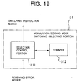
- FIG. 19 is a block diagram showing a configuration of the modulation/coding mode switching selecting portion 51 of FIG. 18.
- the modulation/coding mode switching selecting portion 51 comprises a selection control portion 511 and a counter 512.
- FIG. 20 is a flow chart showing an operation of modulation/coding mode switching selection by the modulation/coding mode switching selecting portion 51 of FIG. 19. The operation of modulation/coding mode switching selection by the modulation/coding mode switching selecting portion 51 will be described with reference to FIGS. 19 and 20.
- the selection control portion 511 of the modulation/coding mode switching selection portion 51 instructs the base station 4 to switch the modulation/coding mode to a slower mode as a modulation/coding mode for the mobile station 5 itself (step S62 in FIG. 20) and clears the counter value C of the counter 512 (C ⁇ 0) (step S63 in FIG. 20).
- the selection control portion 511 increments the counter value C of the counter 512 (C ⁇ C + 1) (step S64 in FIG. 20).
- the selection control portion 511 instructs the base station 4 to switch the modulation/coding mode to a faster mode as a modulation/coding mode for the mobile station 5 itself (step S66 in FIG. 20) and clears the counter value C of the counter 512 (C ⁇ 0) (step S67 in FIG. 20).
- the selection control portion 511 switches the modulation/coding mode to a slower mode if the determination result from the detecting portion 27 shows that a receiving error exists and switches the modulation/coding mode to a faster mode if a data block is successfully received for the predetermined number of blocks Ns or more after performing the switching.
- the mobile station 5 since the mobile station 5 switches the modulation/coding mode at an error of one block, it can promptly switch the modulation/coding mode to a slower mode when conditions of a transmission path are deteriorated. In addition, when a target block error rate is satisfied, the mobile station 5 can immediately switch the modulation/coding mode to a faster mode. Thus, the modulation/coding mode can be promptly switched to an optimal mode in the fifth embodiment of the present invention. In this case, since the predetermined number of blocks Ns is determined according to a target block error rate, the target block error rate can be satisfied.
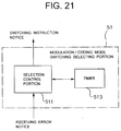
- FIG. 21 is a block diagram showing a configuration of the modulation/coding mode switching selecting portion 51 according to a sixth embodiment of the present invention.
- the modulation/coding mode switching selecting portion 51 comprises the selection control portion 511 and a timer 513.
- the sixth embodiment of the present invention has the same configuration as that of the mobile communication system shown in FIG. 1 and the same configuration as those of the base station 4 according to the fifth embodiment of the present invention shown in FIG. 17 and the mobile station 5 according to the fifth embodiment of the present invention shown in FIG. 18, descriptions on them will be omitted.
- FIG. 22 is a flow chart showing an operation of the modulation/coding mode switching selection by the modulation/coding mode switching selecting portion 51 of FIG. 21.
- the operation of modulation/coding mode switching selection by the modulation/coding mode switching selecting portion 51 according to the sixth embodiment of the present invention will be described with reference to FIGS. 21 and 22.
- the selection control portion 511 of the modulation/coding mode switching selection portion 51 instructs the base station 4 to switch the modulation/coding mode to a slower mode as a modulation/coding mode for the mobile station 5 itself (step S72 in FIG. 22) and resets the timer 513 (step S73 in FIG. 22).
- step S71 in FIG. 22 If the determination result from the error detecting portion 27 does not show a receiving error exists (step S71 in FIG. 22), when a timer value of the timer 513 exceeds the predetermined time Ts (step S74 in FIG. 22), the selection control portion 511 instructs the base station 4 to switch the modulation/coding mode to a faster mode as a modulation/coding mode for the mobile station 5 itself (step S75 in FIG. 22) and resets the timer 513 (step S76 in FIG. 22).
- the selection control portion 511 switches the modulation/coding mode to a slower mode if the determination result from the detecting portion 27 shows that a receiving error exists and switches the modulation/coding mode to a faster mode if a data block is successfully received for the predetermined time Ts or more after performing the switching.
- the mobile station 51 since the mobile station 51 switches the modulation/coding mode at an error of one block, it can promptly switch the modulation/coding mode to a slower mode when conditions of a transmission path are deteriorated. In addition, when a target block error rate is satisfied, the mobile station 5 can immediately switch the modulation/coding mode to a faster mode. Thus, the modulation/coding mode can be promptly switched to an optimal mode in the sixth embodiment of the present invention. In this case, if the predetermined time Ts is time required for transmitting the predetermined number of blocks Ns, since the predetermined time Ts is determined according to a target block error rate, the target block error rate can be satisfied.
- FIG. 23 is a block diagram showing a configuration of the modulation/coding mode switching selecting portion 51 according to a seventh embodiment of the present invention.
- the modulation/coding mode switching selecting portion 51 comprises a selection control portion 514, a receipt failure block number-counter (C1) 515, a receipt failure block number counter (C2) 516, a block number counter (N1) 517 and a block number counter (N2) 518.
- C1 receipt failure block number-counter
- C2 receipt failure block number counter
- N1 block number counter
- N2 block number counter
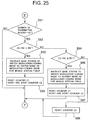
- FIGS. 24 and 25 are a flow chart showing an operation of the modulation/coding mode switching selection by the modulation/coding mode switching selecting portion 51 of FIG. 23.
- the operation of modulation/coding mode switching selection by the modulation/coding mode switching selecting portion 51 according to the seventh embodiment of the present invention will be described with reference to FIGS. 23 to 25.
- the selection control portion 514 of the modulation/coding mode switching selecting portion 51 starts the receipt failure block number counter (C2) 516 (step S82 in FIG. 24).
- the selection control portion 514 also starts the block number counter (N2) 518 following the start of the receipt failure block number counter (C2) 516 and increments the block number counter (N2) 518 each time transmission of a data block is performed.
- the selection control portion 514 starts and increments the receipt failure block number counter (C1) 515 (C1 ⁇ C1+1) (step S84 in FIG. 24) and, at the same time, increments the receipt failure block number counter (C2) 516 (C2 ⁇ C2 + 1) (step S85 in FIG. 24). Further, following the start of the receipt failure block number counter (C1) 515, the selection control portion 514 also starts the block number counter (N1) 517 and increments the block number counter (N1) 517 each time transmission of a data block is performed.
- the selection control portion 514 instructs the base station 4 to switch the modulation/coding mode to a slower mode as a modulation/coding mode for the mobile station 5 itself (step S89 in FIG. 24), resets the receipt failure block number counter (C1) 515 (C1 ⁇ 0), resets the receipt failure block number counter (C2) 516 (C2 ⁇ 0) and restarts the receipt failure block number counter (C2) 516 (step S90 in FIG. 24) and returns to step S81.
- step S94 in FIG. 25 resets the receipt failure block number counter (C1) 515 (C1 ⁇ 0), resets the receipt failure block number counter (C2) 516 (C2 ⁇ 0) and restarts the receipt failure block number counter (C2) 516 (step S94 in FIG. 25) and returns to step S81.
- the selection control portion 514 instructs the base station 4 to switch the modulation/coding mode to a slower mode as a modulation/coding mode for the mobile station 5 itself (step S96 in FIG. 25), resets the receipt failure block number counter (C1) 515 (C1 ⁇ 0), resets the receipt failure block number counter (C2) 516 (C2 ⁇ 0) and restarts the receipt failure block number counter (C2) 516 (step S97 in FIG. 25) and returns to step S81.
- the selection control portion 514 resets the receipt failure block number counter (C2) 516 (C2 ⁇ 0) (step S98 in FIG. 25) and returns to step S81.
- the mobile station 5 since the mobile station 5 switches the modulation/coding mode to a slower mode at the few predetermined number of blocks N1 in response to increase of a block error rate, it can promptly switch the modulation/coding mode to a slower mode when conditions of a transmission path are deteriorated.
- the mobile station 5 since the mobile station 5 switches the modulation/coding mode to a faster mode at the predetermined number of blocks N2 that is larger than the predetermined number of blocks N1 in response to decrease of a block error rate, a target block error rate can be satisfied.
- the modulation/coding mode can be promptly switched to an optimal mode in the seventh embodiment of the present invention.
- unnecessary switching of a mode can be reduced.
- switching to a slower mode is determined according to a plurality of block errors, whereby unnecessary switching of a mode can also be reduced.
- FIG. 26 is a block diagram showing a configuration of the modulation/coding mode switching selecting portion 51 in an eighth embodiment of the present invention.
- the modulation/coding mode switching selecting portion 51 according to the eighth embodiment of the present invention has the same configuration as that of the modulation/coding mode switching selecting portion 51 according to the seventh embodiment of the present invention shown in FIG. 23 except that it is provided with a timer (T1) 519 and a timer (T2) 520 instead of the block number counter (N1) 517 and the block number counter (N2) 518 and the identical elements are denoted by the identical reference numerals.
- T1 519 and a timer (T2) 520 instead of the block number counter (N1) 517 and the block number counter (N2) 518 and the identical elements are denoted by the identical reference numerals.
- operations of the identical elements are the same as those in the seventh embodiment.
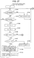
- FIGS. 27 and 28 are a flowchart showing an operation of modulation/coding mode switching selection by the modulation/coding mode switching selecting portion 51 of FIG. 26.
- the operation of modulation/coding mode switching selection by the modulation/coding mode switching selecting portion 51 according to the eighth embodiment of the present invention will be described with reference to FIGS. 26 to 28.
- the selection control portion 514 of the modulation/coding mode switching selecting portion 51 starts the receipt failure block number counter (C2) 516 (step S102 in FIG. 27).
- the selection control portion 514 starts the timer (T2) 520 following the start of the receipt failure block number counter (C2) 516.
- the selection control portion 514 starts and increments the receipt failure block number counter (C1) 515 (C1 ⁇ C1 + 1) (step S104 in FIG. 27) and, at the same time, increments the receipt failure block number counter (C2) 516 (C2 ⁇ C2 + 1) (step S105 in FIG. 27). Further, the selection control portion 514 starts the timer (T1) 519 following the start of the receipt failure block number counter (C1) 515.
- the selection control portion 514 instructs the base station 4 to switch the modulation/coding mode to a slower mode as a modulation/coding mode for the mobile station 5 itself (step S109 in FIG. 27), resets the receipt failure block number counter (C1) 515 (C1 ⁇ 0), resets the receipt failure block number counter (C2) 516 (C2 ⁇ 0) and restarts the receipt failure block number counter (C2) 516 (step S110 in FIG. 27) and returns to step S101.
- step S114 in FIG. 28 resets the receipt failure block number counter (C1) 515 (C1 ⁇ 0), resets the receipt failure block number counter (C2) 516 (C2 ⁇ 0) and restarts the receipt failure block number counter (C2) 516 (step S114 in FIG. 28) and returns to step S101.
- the selection control portion 514 instructs the base station 4 to switch the modulation/coding mode to a slower mode as a modulation/coding mode for the mobile station 5 itself (step S116 in FIG. 28), resets the receipt failure block number counter (C1) 515 (C1 ⁇ 0), resets the receipt failure block number counter (C2) 516 (C2 ⁇ 0) and restarts the receipt failure block number counter (C2) 516 (step S117 in FIG. 28) and returns to step S101.
- the selection control portion 514 resets the receipt failure block number counter (C2) 516 (C2 ⁇ 0) (step S118 in FIG. 28) and returns to step S101.
- the mobile station 5 since the mobile station 5 switches the modulation/coding mode to a slower mode at the short predetermined time T1 in response to increase of a block error rate, it can promptly switch the modulation/coding mode to a slower mode when conditions of a transmission path are deteriorated.
- the mobile station 5 since the mobile station 5 switches the modulation/coding mode to a faster mode at the predetermined time T2 that is longer than the predetermined time T1 in response to decrease of a block error rate, a target block error rate can be satisfied.
- the modulation/coding mode can be promptly switched to an optimal mode in the eighth embodiment of the present invention. In this case, since the switching to a faster mode is monitored at a long period, unnecessary switching of a mode can be reduced. Moreover, since switching to a slower mode is determined according to a plurality of block errors, unnecessary switching of a mode can also be reduced.
- FIG. 29 is a block diagram showing a configuration of a base station 6 according to a ninth embodiment of the present invention.
- the base station 6 according to the ninth embodiment of the present invention has the same configuration as that of the base station 1 according to the first embodiment of the present invention shown in FIG. 2 except that a modulation/coding mode switching determining portion 61 is provided instead of the modulation/coding mode switching selecting portion 15 and the identical elements are denoted by the identical reference numerals.
- the operations of the identical elements are the same as those of the first embodiment of the present invention.
- the modulation/coding mode switching determining portion 61 executes a program stored in the recording medium 20, thereby monitoring a receiving error notice from a not-shown mobile station, and, upon receiving a receiving error notice, forwards the receiving error notice to a not-shown base station control apparatus without adding any change to it.
- the modulation/coding mode switching determining portion 61 also monitors a switching instruction notice from the base station control apparatus and, upon receiving a switching instruction notice, forwards an instruction to switch the modulation/coding mode to a mode slower than a current modulation/coding mode to the control portion 16 and the modulation/coding portion 17, respectively.
- the above-described mobile station has the same configuration and operation as those of the mobile station 2 according to the first embodiment of the present invention shown in FIG. 3.
- FIG. 30 is a block diagram showing a configuration of a base station control apparatus 7 according to the ninth embodiment of the present invention.
- the base station control apparatus 7 is provided with a modulation/coding mode switching selecting portion 71 and the modulation/coding mode switching selecting portion 71 comprises a selection control portion 711 and a counter 712. Further, since a publicly-known technology is applicable to other controlled portions or the like of the base station control apparatus 7, descriptions on configurations and operations of these portions will be omitted.
- FIG. 31 is a flow chart showing an operation of modulation/coding mode switching selection by the modulation/coding mode switching selecting portion 71 of FIG. 30.
- the operation of modulation/coding mode switching selection by the modulation/coding mode switching selecting portion 71 according to the ninth embodiment of the present invention will be described with reference to FIGS. 30 and 31.
- the selection control portion 711 of the modulation/coding mode switching selecting portion 71 instructs the base station 6 to switch the modulation/coding mode to a slower mode as a modulation/coding mode for the pertinent mobile station 2 (step S122 in FIG. 31) and clears a counter value C of the counter 712 (C ⁇ 0) (step S123 in FIG. 31).
- the selection control portion 711 increments the counter value C of the counter 712 (C ⁇ C + 1) (step S124 in FIG. 31).
- the selection control portion 711 instructs the base station 6 to switch the modulation/coding mode to a faster mode as a modulation/coding mode for the pertinent mobile station 2 (step S126 in FIG. 31) and clears the counter value C of the counter 712 (C ⁇ 0) (step S127 in FIG. 31).
- the selection control portion 711 switches the modulation/coding mode to a slower mode and, if a data block is successfully received continuously for the predetermined number of blocks Ns or more after performing the switching, switches the modulation/coding mode to a faster mode.
- the base station control apparatus 7 since the base station control apparatus 7 switches the modulation/coding mode at an error of one block, it can promptly switch the modulation/coding block to a slower mode when conditions of a transmission path are deteriorated. In addition, when a target block error rate is satisfied, the base station control apparatus 7 can immediately switch the modulation/coding mode to a faster mode. Thus, the modulation/coding mode can be promptly switched to an optimal mode in the ninth embodiment of the present invention. In this case, since the predetermined number of blocks Ns is determined according to a target block error rate, the target block error rate can be satisfied.
- FIG. 32 is a block diagram showing a configuration of the modulation/coding mode switching selecting portion 71 according to a tenth embodiment of the present invention.
- the modulation/coding mode switching selecting portion 71 comprises a selection control portion 711 and a timer 713.
- the tenth embodiment of the present invention has the same configuration as that of the mobile communication system shown in FIG. 1 and those of the base station 6 according to the ninth embodiment of the present invention shown in FIG. 29 and the mobile station 2 according to the first embodiment of the present invention shown in FIG. 3, descriptions on them will be omitted.
- FIG. 33 is a flow chart showing an operation of modulation/coding mode switching selection by the modulation/coding mode switching selecting portion 71 of FIG. 32.
- the operation of modulation/coding mode switching selection by the modulation/coding mode switching selecting portion 71 according to the tenth embodiment of the present invention will be described with reference to FIGS. 32 and 33.
- the selection control portion 711 of the modulation/coding mode switching selecting portion 71 Upon receiving a receiving error notice from the mobile station 2 via the base station 6 (step S131 in FIG. 33), the selection control portion 711 of the modulation/coding mode switching selecting portion 71 instructs the base station 6 to switch the modulation/coding mode to a slower mode as a modulation/coding mode for the pertinent mobile station 2 (step S132 in FIG. 33) and resets the timer 713 (step S133 in FIG. 33).
- step S131 in FIG. 33 If a receiving error notice from the mobile station 2 is not received via the base station 6 (step S131 in FIG. 33), when a timer value of the timer 713 exceeds the predetermined time Ts (step S134 in FIG. 33), the selection control portion 711 instructs the base station 6 to switch the modulation/coding mode to a faster mode as amodulation/codingmode for the pertinent mobile station 2 (step S135 in FIG. 33) and resets the timer 713 (step S136 in FIG. 33).
- the selection control portion 711 switches the modulation/coding mode to a slower mode and, when a data block is successfully received continuously for the predetermined time Ts or more after performing the switching, switches the modulation/coding mode to a faster mode.
- the base station control apparatus 7 since the base station control apparatus 7 switches the modulation/coding mode at an error of one block, it can promptly switch the modulation/coding block to a slower mode when conditions of a transmission path are deteriorated. In addition, when a target block error rate is satisfied, the base station control apparatus 7 can immediately switch the modulation/coding mode to a faster mode. Thus, the modulation/coding mode can be promptly switched to an optimal mode in the tenth embodiment of the present invention. In this case, if the predetermined time Ts is time required for transmission of the predetermined number of blocks Ns, since the predetermined time Ts is determined according to a target block error rate, the target block error rate can be satisfied.
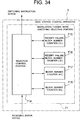
- FIG. 34 is a block diagram showing a configuration of the modulation/coding mode switching selecting portion 71 according to an eleventh embodiment of the present invention.
- the modulation/coding mode switching selecting portion 71 comprises a selection control portion 714, a receipt failure block number counter (C1) 715, a receipt failure block number counter (C2) 716, a block number counter (N1) 717 and a block number counter (N2) 718.
- the eleventh embodiment of the present invention has the same configuration as that of the mobile communication system shown in FIG. 1 and those of the base station 6 according to the ninth embodiment of the present invention shown in FIG. 29 and the mobile station 2 according to the first embodiment of the present invention shown in FIG. 3, descriptions on them will be omitted.
- FIGS. 35 and 36 are a flow chart showing an operation of modulation/coding switching selection by the modulation/coding mode switching selecting portion 71 of FIG. 34.
- the operation of modulation/coding mode switching selection by the modulation/coding mode switching selecting portion 71 according to the eleventh embodiment of the present invention will be described with reference to FIGS. 34 to 36.
- the selection control portion 714 of the modulation/coding mode switching selecting portion 71 starts the receipt failure block number counter (C2) 716 (step S142 in FIG. 35). Following the start of the receipt failure block number counter (C2) 716, the selection control portion 714 also starts the block number counter (N2) 718 and increments the block number counter (N2) 718 each time transmission of a data block is performed.
- the selection control portion 714 starts and increments the receipt failure block number counter (C1) 715 (C1 ⁇ C1 + 1) (step S144 in FIG. 35) and, at the same time, increments the receipt failure block number counter (C2) 716 (C2 ⁇ C2 + 1) (step S145 in FIG. 35). Further, following the start of the receipt failure block number counter (C1) 715, the selection control portion 714 also starts the block number counter (N1) 717 and increments the block number counter (N1) 717 each time transmission of a data block is performed.
- the selection control portion 714 instructs the base station 6 to switch the modulation/coding mode to a slower mode as a modulation/coding mode for the pertinent mobile station 2 (step S149 in FIG. 35), resets the receipt failure block number counter (C1) 715 (C1 ⁇ 0), resets the receipt failure block number counter (C2) 716 (C2 ⁇ 0) and restarts the receipt failure block number counter (C2) 716 (step S150 in FIG. 35) and returns to step S141.
- step S154 in FIG. 36 resets the receipt failure block number counter (C1) 715 (C1 ⁇ 0), resets the receipt failure block number counter (C2) 716 (C2 ⁇ 0) and restarts the receipt failure block number counter (C2) 716 (step S154 in FIG. 36) and returns to step S141.
- the selection control portion 714 instructs the base station 6 to switch the modulation/coding mode to a slower mode as a modulation/coding mode for the pertinent mobile station 2 (step S156 in FIG. 36), resets the receipt failure block number counter (C1) 715 (C1 ⁇ 0), resets the receipt failure block number counter (C2) 716 (C2 ⁇ 0) and restarts the receipt failure block number counter (C2) 716 (step S157 in FIG. 36) and returns to step S141.
- the selection control portion 714 resets the receipt failure block number counter (C2) 716 (C2 ⁇ 0) (step S158 in FIG. 36) and returns to step S141.
- the base station control apparatus 7 since the base station control apparatus 7 switches the modulation/coding mode to a slower mode at the few predetermined number of blocks N1 in response to increase of a block error rate, it can promptly switch the modulation/coding mode to a slower mode when conditions of a transmission path are deteriorated.
- the base station control apparatus 7 switches the modulation/coding mode to a faster mode at the predetermined number of blocks N2 that is larger than the predetermined number of blocks N1 in response to decrease of a block error rate, a target block error rate can be satisfied.
- the modulation/coding mode can be promptly switched to an optimal mode in the eleventh embodiment of the present invention.
- unnecessary switching of a mode can be reduced.
- switching to a slower mode is determined according to a plurality of block errors, whereby unnecessary switching of a mode can also be reduced.
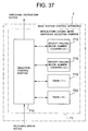
- FIG. 37 is a block diagram showing a configuration of the modulation/coding mode switching selecting portion 71 according to a twelfth embodiment of the present invention.
- the modulation/coding mode switching selecting portion 71 according to the twelfth embodiment of the present invention has the same configuration as that of the modulation/coding mode switching selecting portion 71 according to the eleventh embodiment of the present invention shown in FIG. 34 except that it is provided with a timer (T1) 719 and a timer (T2) 720 instead of the block number counter (N1) 717 and the block number counter (N2) 718 and the identical elements are denoted by the identical reference numerals.
- T1 719 and a timer (T2) 720 instead of the block number counter (N1) 717 and the block number counter (N2) 718 and the identical elements are denoted by the identical reference numerals.
- operations of the identical elements are the same as those in the eleventh embodiment.
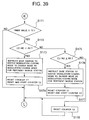
- FIGS. 38 and 39 are a flowchart showing an operation of modulation/coding mode switching selection by the modulation/coding mode switching selecting portion 71 of FIG. 37.
- the operation of modulation/coding mode switching selection by the modulation/coding mode switching selecting portion 71 according to the twelfth embodiment of the present invention will be described with reference to FIGS. 37 to 39.
- the selection control portion 714 of the modulation/coding mode switching selecting portion 71 starts the receipt failure block number counter (C2) 716 (step S162 in FIG. 38).
- the selection control portion 714 starts the timer (T2) 720 following the start of the receipt failure block number counter (C2) 716.
- the selection control portion 714 starts and increments the receipt failure block number counter (C1) 715 (C1 ⁇ C1 + 1) (step S164 in FIG. 38) and, at the same time, increments the receipt failure block number counter (C2) 716 (C2 ⁇ C2 + 1) (step S165 in FIG. 38). Further, the selection control portion 714 starts the timer (T1) 719 following the start of the receipt failure block number counter (C1) 715.
- the selection control portion 714 instructs the base station 6 to switch the modulation/coding mode to a slower mode as a modulation/coding mode for the pertinent mobile station 2 (step S169 in FIG. 38), resets the receipt failure block number counter (C1) 715 (C1 ⁇ 0), resets the receipt failure block number counter (C2) 716 (C2 ⁇ 0) and restarts the receipt failure block number counter (C2) 716 (step S170 in FIG. 38) and returns to step S161.
- step S174 in FIG. 39 resets the receipt failure block number counter (C1) 715 (C1 ⁇ 0), resets the receipt failure block number counter (C2) 716 (C2 ⁇ 0) and restarts the receipt failure block number counter (C2) 716 (step S174 in FIG. 39) and returns to step S161.
- the selection control portion 714 instructs the base station 6 to switch the modulation/coding mode to a slower mode as a modulation/coding mode for the pertinent mobile station 2 (step S176 in FIG. 39), resets the receipt failure block number counter (C1) 715 (C1 ⁇ 0), resets the receipt failure block number counter (C2) 716 (C2 ⁇ 0) and restarts the receipt failure block number counter (C2) 716 (step S177 in FIG. 39) and returns to step S161.
- the selection control portion 714 resets the receipt failure block number counter (C2) 716 (C2 ⁇ 0) (step S178 in FIG. 39) and returns to step S161.
- the base station control apparatus 7 since the base station control apparatus 7 switches the modulation/coding mode to a slower mode at the short predetermined time T1 in response to increase of a block error rate, it can promptly switch the modulation/coding mode to a slower mode when conditions of a transmission path are deteriorated.
- the base station control apparatus 7 switches the modulation/coding mode to a faster mode at the predetermined time T2 that is longer than the predetermined time T1 in response to decrease of a block error rate, a target block error rate can be satisfied.
- the modulation/coding mode can be promptly switched to an optimal mode in the twelfth embodiment of the present invention.
- unnecessary switching of a mode can be reduced.
- switching to a slower mode is determined according to a plurality of block errors, unnecessary switching of a mode can also be reduced.
- a mobile communication system capable of selecting any one of a plurality of modulation/coding modes, which are used for data transmission of a unit of block between a base station controlled by a base station control apparatus and a mobile station, occurrence of a receiving error of a unit of block in data transmission is detected by the mobile station and switching of a modulation/coding mode is performed based on the occurrence of the detected receiving error, whereby selection of an optimal modulation/coding mode can be performed easily.
Landscapes
- Engineering & Computer Science (AREA)
- Computer Networks & Wireless Communication (AREA)
- Signal Processing (AREA)
- Quality & Reliability (AREA)
- Mobile Radio Communication Systems (AREA)
- Detection And Prevention Of Errors In Transmission (AREA)
- Digital Transmission Methods That Use Modulated Carrier Waves (AREA)
Applications Claiming Priority (2)
| Application Number | Priority Date | Filing Date | Title |
|---|---|---|---|
| JP2001053452A JP3596477B2 (ja) | 2001-02-28 | 2001-02-28 | 移動通信システム及びそれに用いる変調・符号化モード切替方法 |
| JP2001053452 | 2001-02-28 |
Publications (2)
| Publication Number | Publication Date |
|---|---|
| EP1237317A2 true EP1237317A2 (de) | 2002-09-04 |
| EP1237317A3 EP1237317A3 (de) | 2007-04-04 |
Family
ID=18913916
Family Applications (1)
| Application Number | Title | Priority Date | Filing Date |
|---|---|---|---|
| EP02004249A Withdrawn EP1237317A3 (de) | 2001-02-28 | 2002-02-26 | Verfahren und System zum Wechsel von Übertragungsmodus |
Country Status (5)
| Country | Link |
|---|---|
| US (1) | US7050761B2 (de) |
| EP (1) | EP1237317A3 (de) |
| JP (1) | JP3596477B2 (de) |
| KR (1) | KR100479311B1 (de) |
| CN (1) | CN1377200A (de) |
Families Citing this family (45)
| Publication number | Priority date | Publication date | Assignee | Title |
|---|---|---|---|---|
| US5754961A (en) | 1994-06-20 | 1998-05-19 | Kabushiki Kaisha Toshiba | Radio communication system including SDL having transmission rate of relatively high speed |
| KR100548899B1 (ko) * | 2001-05-11 | 2006-02-02 | 교세라 가부시키가이샤 | 휴대용 통신 단말기, 무선 데이터 통신 네트워크 시스템, 무선 통신 장치와 그 방법, 및 통신 방식 전환 방법 |
| JP4016647B2 (ja) * | 2001-05-17 | 2007-12-05 | 日本電気株式会社 | 移動通信システム、基地局、移動局及びそれらに用いるしきい値設定方法並びにそのプログラム |
| CN1623290B (zh) * | 2002-02-28 | 2011-10-26 | 富士通株式会社 | 用于cdma中的通信装置 |
| EP1496628B1 (de) * | 2002-04-03 | 2013-06-05 | NEC Corporation | Mobilkommunikationssystem, mobilstation, basisstation, kommunikationsweg-qualitätsschätzverfahren dafür |
| SE0202845D0 (sv) | 2002-05-13 | 2002-09-23 | Ericsson Telefon Ab L M | Measurements for radio resource management for high-speed downlink shared channel (HS-DSCH) |
| JP3887618B2 (ja) * | 2003-08-08 | 2007-02-28 | 松下電器産業株式会社 | 移動局装置および移動局装置における受信方法 |
| JP3994870B2 (ja) | 2002-12-12 | 2007-10-24 | 日本電気株式会社 | 多値qamを用いた無線装置及びしきい値推定方法 |
| US7586874B2 (en) * | 2003-01-06 | 2009-09-08 | Interdigital Technology Corporation | Wireless communication method and apparatus for providing multimedia broadcast services |
| FR2851400B1 (fr) * | 2003-02-18 | 2005-06-10 | Nortel Networks Ltd | Procede de controle d'un mode de compte rendu de mesures sur une interface radio et controleur de reseau radio pour la mise en oeuvre du procede |
| JP4139257B2 (ja) * | 2003-04-01 | 2008-08-27 | 日本電信電話株式会社 | 無線パケット通信方法および無線パケット通信装置 |
| JP4167536B2 (ja) | 2003-04-25 | 2008-10-15 | 松下電器産業株式会社 | 基地局装置、基地局制御装置 |
| WO2004114695A1 (ja) * | 2003-06-19 | 2004-12-29 | Mitsubishi Denki Kabushiki Kaisha | 無線基地局装置と移動体通信システム |
| KR100557191B1 (ko) * | 2003-12-01 | 2006-03-03 | 삼성전자주식회사 | 광대역 무선 접속 통신 시스템에서 셀 커버 영역에 따라 변조 방식을 가변적으로 전환할 수 있는 소프트 변조 전환방법 |
| US20060003747A1 (en) * | 2004-06-01 | 2006-01-05 | Mikolaj Kolakowski | Periodic parameter control command for a wireless mobile device |
| US7899497B2 (en) * | 2004-08-18 | 2011-03-01 | Ruckus Wireless, Inc. | System and method for transmission parameter control for an antenna apparatus with selectable elements |
| US7193562B2 (en) | 2004-11-22 | 2007-03-20 | Ruckus Wireless, Inc. | Circuit board having a peripheral antenna apparatus with selectable antenna elements |
| US7292198B2 (en) | 2004-08-18 | 2007-11-06 | Ruckus Wireless, Inc. | System and method for an omnidirectional planar antenna apparatus with selectable elements |
| US7933628B2 (en) * | 2004-08-18 | 2011-04-26 | Ruckus Wireless, Inc. | Transmission and reception parameter control |
| US7792048B2 (en) * | 2004-09-30 | 2010-09-07 | Alcatel-Lucent Usa Inc. | Outer loop power control in a communication system |
| US7358912B1 (en) | 2005-06-24 | 2008-04-15 | Ruckus Wireless, Inc. | Coverage antenna apparatus with selectable horizontal and vertical polarization elements |
| US8792414B2 (en) | 2005-07-26 | 2014-07-29 | Ruckus Wireless, Inc. | Coverage enhancement using dynamic antennas |
| US9385843B2 (en) * | 2004-12-22 | 2016-07-05 | Qualcomm Incorporated | Method and apparatus for using multiple modulation schemes for a single packet |
| US7893882B2 (en) | 2007-01-08 | 2011-02-22 | Ruckus Wireless, Inc. | Pattern shaping of RF emission patterns |
| US8472448B2 (en) * | 2006-07-21 | 2013-06-25 | Intel Corporation | Wireless adaptive packet control message apparatus, systems, and methods |
| US8670725B2 (en) | 2006-08-18 | 2014-03-11 | Ruckus Wireless, Inc. | Closed-loop automatic channel selection |
| US8396511B2 (en) * | 2007-02-28 | 2013-03-12 | Samsung Electronics Co., Ltd. | Apparatus and method for determining an uplink transmission format in a broadband wireless communication system |
| US8031687B2 (en) * | 2007-07-13 | 2011-10-04 | Kyocera Corporation | Optimized usage of access technology in a multi-mode architecture |
| US9083521B2 (en) | 2008-06-05 | 2015-07-14 | Qualcomm Incorporated | System and method of an in-band modem for data communications over digital wireless communication networks |
| US8964788B2 (en) * | 2008-06-05 | 2015-02-24 | Qualcomm Incorporated | System and method of an in-band modem for data communications over digital wireless communication networks |
| US8958441B2 (en) | 2008-06-05 | 2015-02-17 | Qualcomm Incorporated | System and method of an in-band modem for data communications over digital wireless communication networks |
| EP2293615A1 (de) * | 2008-06-12 | 2011-03-09 | Sharp Kabushiki Kaisha | Relaiseinrichtung, kommunikationssystem und relaisverfahren |
| US8217843B2 (en) | 2009-03-13 | 2012-07-10 | Ruckus Wireless, Inc. | Adjustment of radiation patterns utilizing a position sensor |
| WO2011025205A2 (ko) | 2009-08-24 | 2011-03-03 | 삼성전자 주식회사 | 이동통신 시스템에서 방송 제어 채널 송수신 방법 및 장치 |
| CN101640561B (zh) * | 2009-09-02 | 2013-04-24 | 华为技术有限公司 | 传输模式切换处理方法与装置、基站 |
| US8756668B2 (en) | 2012-02-09 | 2014-06-17 | Ruckus Wireless, Inc. | Dynamic PSK for hotspots |
| US9634403B2 (en) | 2012-02-14 | 2017-04-25 | Ruckus Wireless, Inc. | Radio frequency emission pattern shaping |
| US10186750B2 (en) | 2012-02-14 | 2019-01-22 | Arris Enterprises Llc | Radio frequency antenna array with spacing element |
| US9092610B2 (en) | 2012-04-04 | 2015-07-28 | Ruckus Wireless, Inc. | Key assignment for a brand |
| CN102970119B (zh) * | 2012-11-09 | 2016-01-27 | 大唐移动通信设备有限公司 | 一种由第一传输模式切换为第二传输模式的方法 |
| US20140362786A1 (en) * | 2013-06-05 | 2014-12-11 | Max4G, Inc. | Fixed Wireless Communication With Capacity Enhanced Dynamic Power Control |
| US9769644B2 (en) * | 2014-03-14 | 2017-09-19 | Intel IP Corporation | Systems, methods, and devices for device-to-device communication mode selection |
| JP2016052001A (ja) * | 2014-08-29 | 2016-04-11 | 富士通株式会社 | 無線通信装置、切替方法、及び無線通信システム |
| US10700770B2 (en) * | 2017-08-03 | 2020-06-30 | Vt Idirect, Inc. | System, apparatus, and method for optimal MODCOD selection |
| CN115604236B (zh) * | 2021-07-08 | 2025-03-18 | 大唐移动通信设备有限公司 | 语音切换控制方法、装置及存储介质 |
Family Cites Families (25)
| Publication number | Priority date | Publication date | Assignee | Title |
|---|---|---|---|---|
| JPH06232849A (ja) | 1993-01-29 | 1994-08-19 | Toshiba Corp | 通信システム |
| US5450438A (en) * | 1993-07-26 | 1995-09-12 | At&T Corp. | Fallback method to 1200 bits per second for use in mobile radio |
| US5490168A (en) | 1994-07-08 | 1996-02-06 | Motorola, Inc. | Method and system for automatic optimization of data throughput using variable packet length and code parameters |
| JPH08274756A (ja) | 1995-03-30 | 1996-10-18 | Toshiba Corp | 無線通信システム |
| US5974106A (en) * | 1995-09-01 | 1999-10-26 | Motorola, Inc. | Method and apparatus for multirate data communications |
| US5699365A (en) * | 1996-03-27 | 1997-12-16 | Motorola, Inc. | Apparatus and method for adaptive forward error correction in data communications |
| US5914959A (en) | 1996-10-31 | 1999-06-22 | Glenayre Electronics, Inc. | Digital communications system having an automatically selectable transmission rate |
| US6389066B1 (en) | 1997-09-21 | 2002-05-14 | Lucent Technologies Inc. | System and method for adaptive modification of modulated and coded schemes in a communication system |
| JPH11133621A (ja) * | 1997-10-29 | 1999-05-21 | Canon Inc | 投影露光装置及びそれを用いたデバイスの製造方法 |
| US6728216B1 (en) * | 1998-02-27 | 2004-04-27 | Advanced Micro Devices, Inc. | Arrangement in a network repeater for monitoring link integrity and selectively down shifting link speed based on local configuration signals |
| JP3741866B2 (ja) | 1998-06-05 | 2006-02-01 | 富士通株式会社 | 適応変調方式 |
| US6301265B1 (en) * | 1998-08-14 | 2001-10-09 | Motorola, Inc. | Adaptive rate system and method for network communications |
| JP3450729B2 (ja) | 1998-12-21 | 2003-09-29 | 日本電信電話株式会社 | パケット通信装置 |
| JP2000216723A (ja) | 1999-01-26 | 2000-08-04 | Mitsubishi Electric Corp | 無線機 |
| US6314535B1 (en) | 1999-05-18 | 2001-11-06 | Xircom Wireless, Inc. | Dynamic forward error correction |
| EP1054526A1 (de) * | 1999-05-18 | 2000-11-22 | Lucent Technologies Inc. | Verfahren und System zur Verbindungsanpassung in Telekommunikationsnetzen |
| JP3392077B2 (ja) * | 1999-08-05 | 2003-03-31 | シャープ株式会社 | 無線通信機能付きケーブルモデム |
| US6662009B2 (en) * | 2000-01-20 | 2003-12-09 | Lucent Technologies Inc. | Methods and apparatus for performance testing of cordless telephones |
| US6564055B1 (en) * | 2000-01-21 | 2003-05-13 | Telecommunication Systems, Inc. | Intelligent roaming database (IRDB) updating |
| US6381467B1 (en) * | 2000-06-22 | 2002-04-30 | Motorola, Inc. | Method and apparatus for managing an ad hoc wireless network |
| US6832095B2 (en) * | 2000-07-26 | 2004-12-14 | Interdigital Technology Corporation | Fast adaptive power control adapter for a variable multirate communication system |
| WO2002039650A2 (en) * | 2000-11-09 | 2002-05-16 | Telefonaktiebolaget Lm Ericsson | Device and method for transfer of data packets |
| JP3843329B2 (ja) * | 2000-12-25 | 2006-11-08 | 株式会社日立国際電気 | 適応変調方式制御方法 |
| KR20020066423A (ko) * | 2001-02-10 | 2002-08-17 | 엘지전자 주식회사 | 역방향 링크 데이터 전송속도 송신 장치 및 방법 |
| US7436843B2 (en) * | 2003-04-30 | 2008-10-14 | Telefonaktiebolaget Lm Ericsson (Publ) | Method for access selection |
-
2001
- 2001-02-28 JP JP2001053452A patent/JP3596477B2/ja not_active Expired - Fee Related
-
2002
- 2002-02-26 EP EP02004249A patent/EP1237317A3/de not_active Withdrawn
- 2002-02-27 US US10/083,477 patent/US7050761B2/en not_active Expired - Fee Related
- 2002-02-28 CN CN02119212A patent/CN1377200A/zh active Pending
- 2002-02-28 KR KR10-2002-0010916A patent/KR100479311B1/ko not_active Expired - Fee Related
Also Published As
| Publication number | Publication date |
|---|---|
| EP1237317A3 (de) | 2007-04-04 |
| US7050761B2 (en) | 2006-05-23 |
| JP2002262349A (ja) | 2002-09-13 |
| CN1377200A (zh) | 2002-10-30 |
| JP3596477B2 (ja) | 2004-12-02 |
| US20020119757A1 (en) | 2002-08-29 |
| KR20020070877A (ko) | 2002-09-11 |
| KR100479311B1 (ko) | 2005-03-25 |
Similar Documents
| Publication | Publication Date | Title |
|---|---|---|
| EP1237317A2 (de) | Verfahren und System zum Wechsel von Übertragungsmodus | |
| EP1259015A2 (de) | Auswahl der Kodierungs-/Modulationsart in Mobilkommunikation | |
| JP5049463B2 (ja) | 無線通信システム及び基地局及び移動局及び無線通信方法 | |
| KR100446182B1 (ko) | 자동 재송신 요구를 채용한 통신시스템 | |
| CN1748398B (zh) | 无线电发送装置和传输速率确定方法 | |
| JP3551937B2 (ja) | 移動通信システムにおける通信制御方法及びそれに使用する基地局 | |
| EP1519610A1 (de) | Mobilstation, Basisstation, Kommunikationssystem und Kommunikationsverfahren | |
| CN103209448B (zh) | 无线通信系统 | |
| JP2004072157A (ja) | 移動通信システム及びベストセル変更方法並びにそれに用いる基地局制御装置 | |
| EP0960547A2 (de) | Verfahren und vorrichtung um handoff in einem kommunikationssystem zu kontrollieren | |
| EP1480481A1 (de) | Verfahren zur Übertragungsratenänderung und Basisstation das diese verwendet | |
| NO329130B1 (no) | Kontroll og styring av datasambandet fra flere basestasjoner til en mobil stasjon i et kommunikasjonssystem | |
| EP2253160A1 (de) | Konfiguration für den verbesserten wechsel einer versorgenden hs-dsch-zelle | |
| CN100452758C (zh) | 在umts系统中的报头检测和数据速率控制 | |
| KR20060044708A (ko) | 이동 통신 시스템, 기지국 및 그 내부 이용을 위한 송신전력 제어 방법 | |
| EP1689205B1 (de) | Funkkommunikationsgerät | |
| EP1480365A2 (de) | Auswahl von Transportformat in einem CDMA-Empfänger | |
| KR20010086375A (ko) | 통신 단말 장치 및 송신 전력 제어 방법 | |
| JP2005102073A (ja) | 伝送レート変更方法ならびにそれを利用した基地局装置および端末装置 | |
| WO2006095387A1 (ja) | スケジューリング方法及び基地局装置 | |
| JP2002051007A (ja) | 無線通信装置及び送信電力制御方法 | |
| WO2022258134A1 (en) | Skipped channel buffering | |
| US8781032B2 (en) | Communication terminal and method and program for controlling the same | |
| JP5510474B2 (ja) | 基地局及び移動局及び無線通信システム及び無線通信方法 | |
| JP4793500B2 (ja) | 無線通信システム |
Legal Events
| Date | Code | Title | Description |
|---|---|---|---|
| PUAI | Public reference made under article 153(3) epc to a published international application that has entered the european phase |
Free format text: ORIGINAL CODE: 0009012 |
|
| AK | Designated contracting states |
Kind code of ref document: A2 Designated state(s): AT BE CH CY DE DK ES FI FR GB GR IE IT LI LU MC NL PT SE TR |
|
| AX | Request for extension of the european patent |
Free format text: AL;LT;LV;MK;RO;SI |
|
| PUAL | Search report despatched |
Free format text: ORIGINAL CODE: 0009013 |
|
| AK | Designated contracting states |
Kind code of ref document: A3 Designated state(s): AT BE CH CY DE DK ES FI FR GB GR IE IT LI LU MC NL PT SE TR |
|
| AX | Request for extension of the european patent |
Extension state: AL LT LV MK RO SI |
|
| 17P | Request for examination filed |
Effective date: 20070315 |
|
| AKX | Designation fees paid |
Designated state(s): DE FR GB IT NL |
|
| 17Q | First examination report despatched |
Effective date: 20080115 |
|
| GRAJ | Information related to disapproval of communication of intention to grant by the applicant or resumption of examination proceedings by the epo deleted |
Free format text: ORIGINAL CODE: EPIDOSDIGR1 |
|
| GRAP | Despatch of communication of intention to grant a patent |
Free format text: ORIGINAL CODE: EPIDOSNIGR1 |
|
| RTI1 | Title (correction) |
Free format text: TRANSMISSION MODE SWITCHING METHODS, SYSTEMS AND RECORDING MEDIA |
|
| GRAP | Despatch of communication of intention to grant a patent |
Free format text: ORIGINAL CODE: EPIDOSNIGR1 |
|
| STAA | Information on the status of an ep patent application or granted ep patent |
Free format text: STATUS: THE APPLICATION IS DEEMED TO BE WITHDRAWN |
|
| 18D | Application deemed to be withdrawn |
Effective date: 20110118 |