EP1237224A1 - Antenne und Verfahren zu deren Herstellung - Google Patents
Antenne und Verfahren zu deren Herstellung Download PDFInfo
- Publication number
- EP1237224A1 EP1237224A1 EP02090048A EP02090048A EP1237224A1 EP 1237224 A1 EP1237224 A1 EP 1237224A1 EP 02090048 A EP02090048 A EP 02090048A EP 02090048 A EP02090048 A EP 02090048A EP 1237224 A1 EP1237224 A1 EP 1237224A1
- Authority
- EP
- European Patent Office
- Prior art keywords
- antenna
- antenna structure
- combined
- antenna according
- producing
- Prior art date
- Legal status (The legal status is an assumption and is not a legal conclusion. Google has not performed a legal analysis and makes no representation as to the accuracy of the status listed.)
- Withdrawn
Links
Images
Classifications
-
- H—ELECTRICITY
- H01—ELECTRIC ELEMENTS
- H01Q—ANTENNAS, i.e. RADIO AERIALS
- H01Q9/00—Electrically-short antennas having dimensions not more than twice the operating wavelength and consisting of conductive active radiating elements
- H01Q9/04—Resonant antennas
- H01Q9/0407—Substantially flat resonant element parallel to ground plane, e.g. patch antenna
- H01Q9/0421—Substantially flat resonant element parallel to ground plane, e.g. patch antenna with a shorting wall or a shorting pin at one end of the element
-
- H—ELECTRICITY
- H01—ELECTRIC ELEMENTS
- H01Q—ANTENNAS, i.e. RADIO AERIALS
- H01Q1/00—Details of, or arrangements associated with, antennas
- H01Q1/12—Supports; Mounting means
- H01Q1/22—Supports; Mounting means by structural association with other equipment or articles
- H01Q1/24—Supports; Mounting means by structural association with other equipment or articles with receiving set
- H01Q1/241—Supports; Mounting means by structural association with other equipment or articles with receiving set used in mobile communications, e.g. GSM
- H01Q1/242—Supports; Mounting means by structural association with other equipment or articles with receiving set used in mobile communications, e.g. GSM specially adapted for hand-held use
- H01Q1/243—Supports; Mounting means by structural association with other equipment or articles with receiving set used in mobile communications, e.g. GSM specially adapted for hand-held use with built-in antennas
-
- H—ELECTRICITY
- H01—ELECTRIC ELEMENTS
- H01Q—ANTENNAS, i.e. RADIO AERIALS
- H01Q1/00—Details of, or arrangements associated with, antennas
- H01Q1/36—Structural form of radiating elements, e.g. cone, spiral, umbrella; Particular materials used therewith
- H01Q1/38—Structural form of radiating elements, e.g. cone, spiral, umbrella; Particular materials used therewith formed by a conductive layer on an insulating support
-
- H—ELECTRICITY
- H01—ELECTRIC ELEMENTS
- H01Q—ANTENNAS, i.e. RADIO AERIALS
- H01Q5/00—Arrangements for simultaneous operation of antennas on two or more different wavebands, e.g. dual-band or multi-band arrangements
- H01Q5/30—Arrangements for providing operation on different wavebands
- H01Q5/307—Individual or coupled radiating elements, each element being fed in an unspecified way
- H01Q5/342—Individual or coupled radiating elements, each element being fed in an unspecified way for different propagation modes
- H01Q5/357—Individual or coupled radiating elements, each element being fed in an unspecified way for different propagation modes using a single feed point
-
- H—ELECTRICITY
- H01—ELECTRIC ELEMENTS
- H01Q—ANTENNAS, i.e. RADIO AERIALS
- H01Q7/00—Loop antennas with a substantially uniform current distribution around the loop and having a directional radiation pattern in a plane perpendicular to the plane of the loop
Definitions
- the present invention relates to an antenna, in particular for use in mobile communications.
- PCB multiband antennas are more complex to manufacture and have low reproducibility.
- An object of the invention is to provide an antenna which is able to use multiple frequency bands at the same time cover and has little space.
- an antenna according to the invention in particular a multiband antenna for mobile devices, with one combined antenna structure provided, at least a loop antenna structure with at least one rod antenna structure is combined.
- Antenna structure has that in several frequency bands and / or in one or more broadband Frequency ranges can be interpreted and in any communication terminal can be integrated.
- the correspondingly combined antenna structure can preferably be used in all its dimensions relative to the adaptation to the different requirements from device to device vary in their values.
- the relative remain Dimensions of the combined antenna structure, i.e. the dimensions the loop antenna structure in relation to the rod antenna structure receive.
- the rod antenna structure as a rod or as a meander or in any other form, such as in a waveform can be realized, as can the loop antenna structure in meandering, rod or other suitable Form.
- the combined antenna structure is preferably designed such that that space optimization adapted to the respective device he follows.
- the combined antenna structure preferably has in the Frequency band with the lowest frequency is a loop antenna structure on. So she owns at least there a ground contact.
- the ground contact can in principle on everyone any position of the antenna structure can be attached. However, it is preferably provided at the end of the structure, i.e. the combined antenna structure preferably has at least one of its ends has a ground contact on. This makes the frequency lower.
- the radiating element can be used for reasons of space can also be carried out in another form. Preferably this structure becomes the maximum distance from the ground contact of the second radiating element.
- the Antenna also made of several radiating structures as one in Form of a loop antenna structure and / or a rod antenna structure consist of a multi-band antenna with more to be realized as two bands.
- the position of the antenna on or in the respective device is irrelevant. It can depend on the respective device properties and the type of use can be adjusted.
- the rod antenna structure is preferably located on the end face of the device. Always pay attention to the distance of the Radiator element to the ground surface.
- Antenna has the combined antenna structure as contact elements at least one RF contact and at least a ground contact. In principle there are also several Ground contacts possible for a desired antenna behavior adjust.
- the RF contact is preferably at the beginning of the Attached meandering, but can also be in another place be positioned.
- Antennas are tuning elements on the combined antenna structure intended. These can be nearby, i.e. below, above or next to one or more radiant Structures.
- the tuning elements can, for example in the form of a patch.
- the antenna can also have a stepped or compressed structure have, i.e. the height of the antenna above the corresponding device PCB can both in terms of their length and their Vary in width.
- the contour of the emitter element is preferably the antenna according to the invention the course of the housing adjusted to use the volume as well as possible.
- the radiation properties are improved and increases the bandwidth by making the plane of the antenna parallel runs to the metallic surface of the device.
- she can also be at a variable distance from the metallic EMC shielding of the radio-operated communication terminal run.
- Antenna has the antenna structure suitable dielectric and / or magnetic materials.
- dielectric and / or magnetic materials can affect the antenna structure fill in partially or completely. They are too Combinations of different dielectric and / or magnetic Substances or air possible.
- a first preferred method according to the invention for Production of an antenna according to the invention becomes the antenna realized on a PCB (Printed Circiut Board).
- an antenna according to the invention is made from a Sheet metal is manufactured using a stamping and bending technique.
- the antenna according to the invention can be used according to the invention as run a slide.
- the structuring can be done using different technologies, known from the selective structuring of the so-called MID applications.
- full-surface metallization with subsequent laser structuring the application of a primer for metallization by masking or pad printing (Boymetec process) and subsequent metallization.
- metallization is chemical deposition and / or galvanic Deposition of metals.
- Another variant is z. B. the printing of a conductive lacquer by stamp, tampon or screen printing.
- the material on which the structure in the case of the PCB and the MID technology is applied is freely selectable. Preferably it is suitable for high frequencies. It can also be pliable flexible Be material, which means an adaptation to housing or device contours is possible.
- the invention further comprises the use of the invention Antenna for installation or integration into a communication terminal, especially in a mobile device.
- the Antenna according to the invention can also in any way be connected to the communication terminal, for example be placed on the outside or fold out or it can on a conventional circuit board, for example in GSM desk phones mounted in radio or telecommunications modules become. Ultimately, it can also function as an independent external Antenna operated. In all cases, a suitable antenna dimensions are observed.
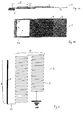
- FIGs 1a and 1b is a side and a top view of a Part of a mobile device 1 shown, in which a antenna 2 according to the invention is integrated.
- a PCB 3 on which a shield cover 4 rests and at one end there is an earpiece 5.
- the integrated antenna 2 according to the invention is located in a suitable distance h2 to the screen cover 4.
- the height of the Antenna 2 above the device PCB 3 can be within the length and / or the width vary.
- the plane preferably runs the antenna 2 parallel to the metallic surface. Thereby the radiation properties can be improved and the bandwidth will be increased. But it can also be in a variable Distance to the metallic EMC shield 4 of the mobile device 1 run.
- FIG. 1b shows a top view of part of a mobile radio device 1 with an integrated antenna according to the invention 2.
- the PCB 3 and the one on it can be seen attached shield cover 4.
- the antenna 2 has two contact elements on, namely an RF contact 6 and a ground contact 7.
- the position of the antenna in the device is irrelevant, can therefore the device properties and the type of application be adjusted.
- the rod antenna structure is preferably located on the front of the device.
- Figure 2 shows the basic structure of an embodiment an antenna according to the invention 2. All dimensions can be Adaptation to the set, different from device to device Requirements vary in their values.
- the rod 8 can also be in a meander shape, the meander 9 in Bar shape or in any other shape can be realized.
- the tape preferably forms the lower frequency has the loop antenna structure 10 and thus ground contact 11.
- the ground contact 11 can on everyone any position of the loop antenna structure 10 attached become. However, as shown here, it is preferably due to End of structure.
- the RF contact 12 is here at the beginning of Maender's 9, i.e. at the transition from the rod antenna structure 13 to the loop antenna structure 10.
Landscapes
- Engineering & Computer Science (AREA)
- Computer Networks & Wireless Communication (AREA)
- Support Of Aerials (AREA)
- Details Of Aerials (AREA)
Abstract
Description
Claims (11)
- Antenne (2), insbesondere integrierbare Multiband-Antenne für Mobilfunkgeräte (1), mit einer kombinierten Antennenstruktur, wobei mindestens eine Loop-Antennenstruktur (10) mit mindestens einer Stab-Antennenstruktur (13) kombiniert ist.
- Antenne (2) nach Anspruch 1,
dadurch gekennzeichnet, dass die kombinierte Antennenstruktur in dem Frequenzband mit der tiefsten Frequenz eine Loop-Antennenstruktur (10) aufweist. - Antenne nach einem der vorhergehenden Ansprüche,
dadurch gekennzeichnet,
die kombinierte Antennenstruktur mindestens an einem ihrer Enden einen Massekontakt (11) aufweist. - Antenne nach einem der vorhergehenden Ansprüche,
dadurch gekennzeichnet, dass die kombinierte Antennenstruktur als Kontaktelemente mindestens einen HF-Kontakt (12) und mindestens einen Massekontakt (11) aufweist. - Antenne nach einem der vorhergehenden Ansprüche,
dadurch gekennzeichnet, dass an der kombinierten Antennenstruktur Abstimmelemente vorgesehen sind. - Antenne nach einem der vorhergehenden Ansprüche,
dadurch gekennzeichnet, dass die Antennenstruktur geeignete dielektrische und/oder magnetische Materialien aufweist. - Verfahren zur Herstellung einer Antenne gemäß einem der Ansprüche 1 bis 6,
dadurch gekennzeichnet, dass die Antenne auf einem PCB (Printed Circiut Board) realisiert wird. - Verfahren zur Herstellung einer Antenne gemäß einem der Ansprüche 1 bis 6,
dadurch gekennzeichnet, dass die Antenne aus einem Blech mittels einer Stanz-Biege-Technik hergestellt wird. - Verfahren zur Herstellung einer Antenne gemäß einem der Ansprüche 1 bis 6,
dadurch gekennzeichnet, dass die Antenne als eine Folie ausgeführt wird. - Verfahren zur Herstellung einer Antenne gemäß einem der Ansprüche 1 bis 6,
dadurch gekennzeichnet, dass die Antenne in der MID-Technik (Moulded Interconnected Device) ausgeführt wird. - Verwendung der Antenne gemäß den Ansprüchen 1 bis 6 zum Einbau oder zur Integration in ein Kommunikationsendgerät, insbesondere in ein Mobilfunkgerät.
Applications Claiming Priority (2)
| Application Number | Priority Date | Filing Date | Title |
|---|---|---|---|
| DE10108859 | 2001-02-14 | ||
| DE10108859A DE10108859A1 (de) | 2001-02-14 | 2001-02-14 | Antenne und Verfahren zu deren Herstellung |
Publications (1)
| Publication Number | Publication Date |
|---|---|
| EP1237224A1 true EP1237224A1 (de) | 2002-09-04 |
Family
ID=7675309
Family Applications (1)
| Application Number | Title | Priority Date | Filing Date |
|---|---|---|---|
| EP02090048A Withdrawn EP1237224A1 (de) | 2001-02-14 | 2002-02-06 | Antenne und Verfahren zu deren Herstellung |
Country Status (2)
| Country | Link |
|---|---|
| EP (1) | EP1237224A1 (de) |
| DE (1) | DE10108859A1 (de) |
Cited By (17)
| Publication number | Priority date | Publication date | Assignee | Title |
|---|---|---|---|---|
| WO2004057701A1 (en) * | 2002-12-22 | 2004-07-08 | Fractus S.A. | Multi-band monopole antenna for a mobile communications device |
| US6809692B2 (en) | 2000-04-19 | 2004-10-26 | Advanced Automotive Antennas, S.L. | Advanced multilevel antenna for motor vehicles |
| US6870507B2 (en) | 2001-02-07 | 2005-03-22 | Fractus S.A. | Miniature broadband ring-like microstrip patch antenna |
| WO2005045990A1 (en) | 2003-10-22 | 2005-05-19 | Sony Ericsson Mobile Communications Ab | Multi-band antennas and radio apparatus incorporating the same |
| US6937206B2 (en) | 2001-04-16 | 2005-08-30 | Fractus, S.A. | Dual-band dual-polarized antenna array |
| US6937191B2 (en) | 1999-10-26 | 2005-08-30 | Fractus, S.A. | Interlaced multiband antenna arrays |
| EP1601049A1 (de) * | 2004-05-19 | 2005-11-30 | Delphi Technologies, Inc. | Schleifenantenne für zwei Frequenzbereiche |
| US7015868B2 (en) | 1999-09-20 | 2006-03-21 | Fractus, S.A. | Multilevel Antennae |
| US7148850B2 (en) | 2000-01-19 | 2006-12-12 | Fractus, S.A. | Space-filling miniature antennas |
| EP1742290A1 (de) * | 2005-07-04 | 2007-01-10 | Samsung Electronics Co., Ltd. | Interne Antennenstruktur für ein Mobilgerät and Verfahren zur deren Herstellung |
| US7202818B2 (en) | 2001-10-16 | 2007-04-10 | Fractus, S.A. | Multifrequency microstrip patch antenna with parasitic coupled elements |
| US7215287B2 (en) | 2001-10-16 | 2007-05-08 | Fractus S.A. | Multiband antenna |
| US7312762B2 (en) | 2001-10-16 | 2007-12-25 | Fractus, S.A. | Loaded antenna |
| US7423592B2 (en) | 2004-01-30 | 2008-09-09 | Fractus, S.A. | Multi-band monopole antennas for mobile communications devices |
| US7511675B2 (en) | 2000-10-26 | 2009-03-31 | Advanced Automotive Antennas, S.L. | Antenna system for a motor vehicle |
| US8738103B2 (en) | 2006-07-18 | 2014-05-27 | Fractus, S.A. | Multiple-body-configuration multimedia and smartphone multifunction wireless devices |
| US9755314B2 (en) | 2001-10-16 | 2017-09-05 | Fractus S.A. | Loaded antenna |
Citations (5)
| Publication number | Priority date | Publication date | Assignee | Title |
|---|---|---|---|---|
| WO1999025042A1 (en) * | 1997-11-06 | 1999-05-20 | Telefonaktiebolaget Lm Ericsson | A portable electronic communication device with multi-band antenna system |
| EP0944128A1 (de) * | 1998-03-18 | 1999-09-22 | Murata Manufacturing Co., Ltd. | Antennenanordnung und tragbares Funkgerät mit einer solchen Antennenanordnung |
| WO1999067851A1 (en) * | 1998-06-24 | 1999-12-29 | Allgon Ab | An antenna device, a method for manufacturing an antenna device and a radio communication device including an antenna device |
| EP0986130A2 (de) * | 1998-09-08 | 2000-03-15 | Siemens Aktiengesellschaft | Antenne für funkbetriebene Kommunikationsendgeräte |
| WO2000052784A1 (de) * | 1999-03-01 | 2000-09-08 | Siemens Aktiengesellschaft | Integrierbare multiband-antenne |
Family Cites Families (5)
| Publication number | Priority date | Publication date | Assignee | Title |
|---|---|---|---|---|
| US5300936A (en) * | 1992-09-30 | 1994-04-05 | Loral Aerospace Corp. | Multiple band antenna |
| FI110394B (fi) * | 1996-08-06 | 2003-01-15 | Filtronic Lk Oy | Yhdistelmäantenni |
| SE511501C2 (sv) * | 1997-07-09 | 1999-10-11 | Allgon Ab | Kompakt antennanordning |
| EP0933832A3 (de) * | 1998-01-30 | 2001-04-11 | Matsushita Electric Industrial Co., Ltd. | Eingebaute Antenne für Funkübertragungsendgeräte |
| KR100263181B1 (ko) * | 1998-02-27 | 2000-08-01 | 윤종용 | 휴대용 무선 단말기 안테나 |
-
2001
- 2001-02-14 DE DE10108859A patent/DE10108859A1/de not_active Withdrawn
-
2002
- 2002-02-06 EP EP02090048A patent/EP1237224A1/de not_active Withdrawn
Patent Citations (5)
| Publication number | Priority date | Publication date | Assignee | Title |
|---|---|---|---|---|
| WO1999025042A1 (en) * | 1997-11-06 | 1999-05-20 | Telefonaktiebolaget Lm Ericsson | A portable electronic communication device with multi-band antenna system |
| EP0944128A1 (de) * | 1998-03-18 | 1999-09-22 | Murata Manufacturing Co., Ltd. | Antennenanordnung und tragbares Funkgerät mit einer solchen Antennenanordnung |
| WO1999067851A1 (en) * | 1998-06-24 | 1999-12-29 | Allgon Ab | An antenna device, a method for manufacturing an antenna device and a radio communication device including an antenna device |
| EP0986130A2 (de) * | 1998-09-08 | 2000-03-15 | Siemens Aktiengesellschaft | Antenne für funkbetriebene Kommunikationsendgeräte |
| WO2000052784A1 (de) * | 1999-03-01 | 2000-09-08 | Siemens Aktiengesellschaft | Integrierbare multiband-antenne |
Cited By (72)
| Publication number | Priority date | Publication date | Assignee | Title |
|---|---|---|---|---|
| US8154463B2 (en) | 1999-09-20 | 2012-04-10 | Fractus, S.A. | Multilevel antennae |
| US7528782B2 (en) | 1999-09-20 | 2009-05-05 | Fractus, S.A. | Multilevel antennae |
| US10056682B2 (en) | 1999-09-20 | 2018-08-21 | Fractus, S.A. | Multilevel antennae |
| US9761934B2 (en) | 1999-09-20 | 2017-09-12 | Fractus, S.A. | Multilevel antennae |
| US9362617B2 (en) | 1999-09-20 | 2016-06-07 | Fractus, S.A. | Multilevel antennae |
| US9240632B2 (en) | 1999-09-20 | 2016-01-19 | Fractus, S.A. | Multilevel antennae |
| US9054421B2 (en) | 1999-09-20 | 2015-06-09 | Fractus, S.A. | Multilevel antennae |
| US7123208B2 (en) | 1999-09-20 | 2006-10-17 | Fractus, S.A. | Multilevel antennae |
| US9000985B2 (en) | 1999-09-20 | 2015-04-07 | Fractus, S.A. | Multilevel antennae |
| US8976069B2 (en) | 1999-09-20 | 2015-03-10 | Fractus, S.A. | Multilevel antennae |
| US8941541B2 (en) | 1999-09-20 | 2015-01-27 | Fractus, S.A. | Multilevel antennae |
| US8330659B2 (en) | 1999-09-20 | 2012-12-11 | Fractus, S.A. | Multilevel antennae |
| US8009111B2 (en) | 1999-09-20 | 2011-08-30 | Fractus, S.A. | Multilevel antennae |
| US8154462B2 (en) | 1999-09-20 | 2012-04-10 | Fractus, S.A. | Multilevel antennae |
| US7015868B2 (en) | 1999-09-20 | 2006-03-21 | Fractus, S.A. | Multilevel Antennae |
| US7505007B2 (en) | 1999-09-20 | 2009-03-17 | Fractus, S.A. | Multi-level antennae |
| US7397431B2 (en) | 1999-09-20 | 2008-07-08 | Fractus, S.A. | Multilevel antennae |
| US7394432B2 (en) | 1999-09-20 | 2008-07-01 | Fractus, S.A. | Multilevel antenna |
| US7557768B2 (en) | 1999-10-26 | 2009-07-07 | Fractus, S.A. | Interlaced multiband antenna arrays |
| US8896493B2 (en) | 1999-10-26 | 2014-11-25 | Fractus, S.A. | Interlaced multiband antenna arrays |
| US8228256B2 (en) | 1999-10-26 | 2012-07-24 | Fractus, S.A. | Interlaced multiband antenna arrays |
| US9905940B2 (en) | 1999-10-26 | 2018-02-27 | Fractus, S.A. | Interlaced multiband antenna arrays |
| US6937191B2 (en) | 1999-10-26 | 2005-08-30 | Fractus, S.A. | Interlaced multiband antenna arrays |
| US7250918B2 (en) | 1999-10-26 | 2007-07-31 | Fractus, S.A. | Interlaced multiband antenna arrays |
| US7932870B2 (en) | 1999-10-26 | 2011-04-26 | Fractus, S.A. | Interlaced multiband antenna arrays |
| US8212726B2 (en) | 2000-01-19 | 2012-07-03 | Fractus, Sa | Space-filling miniature antennas |
| US10355346B2 (en) | 2000-01-19 | 2019-07-16 | Fractus, S.A. | Space-filling miniature antennas |
| US7554490B2 (en) | 2000-01-19 | 2009-06-30 | Fractus, S.A. | Space-filling miniature antennas |
| US8558741B2 (en) | 2000-01-19 | 2013-10-15 | Fractus, S.A. | Space-filling miniature antennas |
| US8471772B2 (en) | 2000-01-19 | 2013-06-25 | Fractus, S.A. | Space-filling miniature antennas |
| US8207893B2 (en) | 2000-01-19 | 2012-06-26 | Fractus, S.A. | Space-filling miniature antennas |
| US9331382B2 (en) | 2000-01-19 | 2016-05-03 | Fractus, S.A. | Space-filling miniature antennas |
| US7202822B2 (en) | 2000-01-19 | 2007-04-10 | Fractus, S.A. | Space-filling miniature antennas |
| US8610627B2 (en) | 2000-01-19 | 2013-12-17 | Fractus, S.A. | Space-filling miniature antennas |
| US7148850B2 (en) | 2000-01-19 | 2006-12-12 | Fractus, S.A. | Space-filling miniature antennas |
| US6809692B2 (en) | 2000-04-19 | 2004-10-26 | Advanced Automotive Antennas, S.L. | Advanced multilevel antenna for motor vehicles |
| US7511675B2 (en) | 2000-10-26 | 2009-03-31 | Advanced Automotive Antennas, S.L. | Antenna system for a motor vehicle |
| US6870507B2 (en) | 2001-02-07 | 2005-03-22 | Fractus S.A. | Miniature broadband ring-like microstrip patch antenna |
| US6937206B2 (en) | 2001-04-16 | 2005-08-30 | Fractus, S.A. | Dual-band dual-polarized antenna array |
| US7439923B2 (en) | 2001-10-16 | 2008-10-21 | Fractus, S.A. | Multiband antenna |
| US7541997B2 (en) | 2001-10-16 | 2009-06-02 | Fractus, S.A. | Loaded antenna |
| US8228245B2 (en) | 2001-10-16 | 2012-07-24 | Fractus, S.A. | Multiband antenna |
| US7202818B2 (en) | 2001-10-16 | 2007-04-10 | Fractus, S.A. | Multifrequency microstrip patch antenna with parasitic coupled elements |
| US7312762B2 (en) | 2001-10-16 | 2007-12-25 | Fractus, S.A. | Loaded antenna |
| US8723742B2 (en) | 2001-10-16 | 2014-05-13 | Fractus, S.A. | Multiband antenna |
| US7920097B2 (en) | 2001-10-16 | 2011-04-05 | Fractus, S.A. | Multiband antenna |
| US9755314B2 (en) | 2001-10-16 | 2017-09-05 | Fractus S.A. | Loaded antenna |
| US7215287B2 (en) | 2001-10-16 | 2007-05-08 | Fractus S.A. | Multiband antenna |
| EP2273611A1 (de) * | 2002-12-22 | 2011-01-12 | Fractus, S.A. | Mehrband-monopolantenne für ein Mobilfunkgerät |
| US7675470B2 (en) | 2002-12-22 | 2010-03-09 | Fractus, S.A. | Multi-band monopole antenna for a mobile communications device |
| US7403164B2 (en) | 2002-12-22 | 2008-07-22 | Fractus, S.A. | Multi-band monopole antenna for a mobile communications device |
| US7411556B2 (en) | 2002-12-22 | 2008-08-12 | Fractus, S.A. | Multi-band monopole antenna for a mobile communications device |
| US8253633B2 (en) | 2002-12-22 | 2012-08-28 | Fractus, S.A. | Multi-band monopole antenna for a mobile communications device |
| US8674887B2 (en) | 2002-12-22 | 2014-03-18 | Fractus, S.A. | Multi-band monopole antenna for a mobile communications device |
| US8259016B2 (en) | 2002-12-22 | 2012-09-04 | Fractus, S.A. | Multi-band monopole antenna for a mobile communications device |
| JP2006510321A (ja) * | 2002-12-22 | 2006-03-23 | フラクタス・ソシエダッド・アノニマ | 移動通信デバイス用のマルチバンド・モノポール・アンテナ |
| US8456365B2 (en) | 2002-12-22 | 2013-06-04 | Fractus, S.A. | Multi-band monopole antennas for mobile communications devices |
| WO2004057701A1 (en) * | 2002-12-22 | 2004-07-08 | Fractus S.A. | Multi-band monopole antenna for a mobile communications device |
| WO2005045990A1 (en) | 2003-10-22 | 2005-05-19 | Sony Ericsson Mobile Communications Ab | Multi-band antennas and radio apparatus incorporating the same |
| US7592958B2 (en) | 2003-10-22 | 2009-09-22 | Sony Ericsson Mobile Communications, Ab | Multi-band antennas and radio apparatus incorporating the same |
| US7423592B2 (en) | 2004-01-30 | 2008-09-09 | Fractus, S.A. | Multi-band monopole antennas for mobile communications devices |
| US7710335B2 (en) | 2004-05-19 | 2010-05-04 | Delphi Technologies, Inc. | Dual band loop antenna |
| EP1601049A1 (de) * | 2004-05-19 | 2005-11-30 | Delphi Technologies, Inc. | Schleifenantenne für zwei Frequenzbereiche |
| EP1742290A1 (de) * | 2005-07-04 | 2007-01-10 | Samsung Electronics Co., Ltd. | Interne Antennenstruktur für ein Mobilgerät and Verfahren zur deren Herstellung |
| US9099773B2 (en) | 2006-07-18 | 2015-08-04 | Fractus, S.A. | Multiple-body-configuration multimedia and smartphone multifunction wireless devices |
| US8738103B2 (en) | 2006-07-18 | 2014-05-27 | Fractus, S.A. | Multiple-body-configuration multimedia and smartphone multifunction wireless devices |
| US9899727B2 (en) | 2006-07-18 | 2018-02-20 | Fractus, S.A. | Multiple-body-configuration multimedia and smartphone multifunction wireless devices |
| US10644380B2 (en) | 2006-07-18 | 2020-05-05 | Fractus, S.A. | Multiple-body-configuration multimedia and smartphone multifunction wireless devices |
| US11031677B2 (en) | 2006-07-18 | 2021-06-08 | Fractus, S.A. | Multiple-body-configuration multimedia and smartphone multifunction wireless devices |
| US11349200B2 (en) | 2006-07-18 | 2022-05-31 | Fractus, S.A. | Multiple-body-configuration multimedia and smartphone multifunction wireless devices |
| US11735810B2 (en) | 2006-07-18 | 2023-08-22 | Fractus, S.A. | Multiple-body-configuration multimedia and smartphone multifunction wireless devices |
| US12095149B2 (en) | 2006-07-18 | 2024-09-17 | Fractus, S.A. | Multiple-body-configuration multimedia and smartphone multifunction wireless devices |
Also Published As
| Publication number | Publication date |
|---|---|
| DE10108859A1 (de) | 2003-05-22 |
Similar Documents
| Publication | Publication Date | Title |
|---|---|---|
| EP1195845B1 (de) | Miniaturisierte Mikrowellenantenne | |
| EP1204160B1 (de) | Mehrband-Mikrowellenantenne | |
| DE60211316T2 (de) | Antennenanordnung | |
| DE102007056258B4 (de) | Chipantenne und zugehörige Leiterplatte für ein mobiles Telekommunikationsgerät | |
| EP1237224A1 (de) | Antenne und Verfahren zu deren Herstellung | |
| EP0841715B1 (de) | Flachantenne | |
| DE60218056T2 (de) | Drahtloses funkgerät | |
| DE102005015561A1 (de) | Interne Breitbandantenne | |
| DE10347722A1 (de) | Drahtlose LAN-Antenne und zugehörige drahtlose LAN-Karte | |
| WO2002015333A1 (de) | Antennenanordnung eines mobilen kommunikationsendgerätes, insbesondere eines mobiltelefons | |
| DE19824145A1 (de) | Integrierte Antennenanordnung für mobile Telekommunikations-Endgeräte | |
| EP1829158B1 (de) | Disc-monopol-antennenstruktur | |
| DE3486135T2 (de) | Antenne fuer den mobilen telefonverkehr. | |
| WO2000052784A1 (de) | Integrierbare multiband-antenne | |
| DE10049843A1 (de) | Fleckenmusterantenne für den Mikrowellenbereich | |
| DE10292326T5 (de) | Antennenvorrichtung und drahtlose Vorrichtung die diese verwendet | |
| DE60126989T2 (de) | Antenneneinrichtung und verfahren zur einstellung der antenneneinrichtung | |
| DE60208731T2 (de) | Eingebaute Mehrband-Planarantenne mit Inverted-L-Haupt- und Parasitär- Antennenelementen | |
| DE19983744B4 (de) | Antennenvorrichtung | |
| EP1086509B1 (de) | Antennenanordnung und funkgerät | |
| DE60314365T2 (de) | Kombinierte Lautsprecher- und Antennenkomponente | |
| DE60313588T2 (de) | Mikrowellenantenne | |
| DE60301541T2 (de) | Eingebaute Antenne, elektronisches Gerät mit einer derartigen Antenne sowie Verfahren zur Herstellung und zum Einbau dieser Antenne | |
| DE102006058934A1 (de) | Antennenvorrichtung und mobile Datenübertragungseinrichtung, welche diese verwendet | |
| DE102004063266A1 (de) | Flachprofilantenne für ein Fahrzeug-Fernkommunikationssystem |
Legal Events
| Date | Code | Title | Description |
|---|---|---|---|
| PUAI | Public reference made under article 153(3) epc to a published international application that has entered the european phase |
Free format text: ORIGINAL CODE: 0009012 |
|
| AK | Designated contracting states |
Kind code of ref document: A1 Designated state(s): AT BE CH CY DE DK ES FI FR GB GR IE IT LI LU MC NL PT SE TR |
|
| AX | Request for extension of the european patent |
Free format text: AL;LT;LV;MK;RO;SI |
|
| AKX | Designation fees paid | ||
| 17P | Request for examination filed |
Effective date: 20030407 |
|
| RBV | Designated contracting states (corrected) |
Designated state(s): AT BE CH CY DE DK ES FI FR GB GR IE IT LI LU MC NL PT SE TR |
|
| REG | Reference to a national code |
Ref country code: DE Ref legal event code: 8566 |
|
| 17Q | First examination report despatched |
Effective date: 20030523 |
|
| STAA | Information on the status of an ep patent application or granted ep patent |
Free format text: STATUS: THE APPLICATION IS DEEMED TO BE WITHDRAWN |
|
| 18D | Application deemed to be withdrawn |
Effective date: 20031003 |