EP1237155A1 - Feuille pour enregistrement optique, procédé pour sa fabrication, support d' enregistrement optique, procédé pour sa fabrication, procédé d' enregistrement optique, appareil d'enregistrement/reproduction d' information, procédé de reproduction/enregistrement d' information, système d' ordinateur et système d' enregistrement/reproduction de signaux vidéo - Google Patents
Feuille pour enregistrement optique, procédé pour sa fabrication, support d' enregistrement optique, procédé pour sa fabrication, procédé d' enregistrement optique, appareil d'enregistrement/reproduction d' information, procédé de reproduction/enregistrement d' information, système d' ordinateur et système d' enregistrement/reproduction de signaux vidéo Download PDFInfo
- Publication number
- EP1237155A1 EP1237155A1 EP20020004522 EP02004522A EP1237155A1 EP 1237155 A1 EP1237155 A1 EP 1237155A1 EP 20020004522 EP20020004522 EP 20020004522 EP 02004522 A EP02004522 A EP 02004522A EP 1237155 A1 EP1237155 A1 EP 1237155A1
- Authority
- EP
- European Patent Office
- Prior art keywords
- light
- optical recording
- chemisorptive
- recording
- group
- Prior art date
- Legal status (The legal status is an assumption and is not a legal conclusion. Google has not performed a legal analysis and makes no representation as to the accuracy of the status listed.)
- Granted
Links
Images


Classifications
-
- G—PHYSICS
- G11—INFORMATION STORAGE
- G11B—INFORMATION STORAGE BASED ON RELATIVE MOVEMENT BETWEEN RECORD CARRIER AND TRANSDUCER
- G11B7/00—Recording or reproducing by optical means, e.g. recording using a thermal beam of optical radiation by modifying optical properties or the physical structure, reproducing using an optical beam at lower power by sensing optical properties; Record carriers therefor
- G11B7/24—Record carriers characterised by shape, structure or physical properties, or by the selection of the material
- G11B7/241—Record carriers characterised by shape, structure or physical properties, or by the selection of the material characterised by the selection of the material
- G11B7/252—Record carriers characterised by shape, structure or physical properties, or by the selection of the material characterised by the selection of the material of layers other than recording layers
-
- B—PERFORMING OPERATIONS; TRANSPORTING
- B82—NANOTECHNOLOGY
- B82Y—SPECIFIC USES OR APPLICATIONS OF NANOSTRUCTURES; MEASUREMENT OR ANALYSIS OF NANOSTRUCTURES; MANUFACTURE OR TREATMENT OF NANOSTRUCTURES
- B82Y10/00—Nanotechnology for information processing, storage or transmission, e.g. quantum computing or single electron logic
-
- B—PERFORMING OPERATIONS; TRANSPORTING
- B82—NANOTECHNOLOGY
- B82Y—SPECIFIC USES OR APPLICATIONS OF NANOSTRUCTURES; MEASUREMENT OR ANALYSIS OF NANOSTRUCTURES; MANUFACTURE OR TREATMENT OF NANOSTRUCTURES
- B82Y30/00—Nanotechnology for materials or surface science, e.g. nanocomposites
-
- G—PHYSICS
- G11—INFORMATION STORAGE
- G11B—INFORMATION STORAGE BASED ON RELATIVE MOVEMENT BETWEEN RECORD CARRIER AND TRANSDUCER
- G11B7/00—Recording or reproducing by optical means, e.g. recording using a thermal beam of optical radiation by modifying optical properties or the physical structure, reproducing using an optical beam at lower power by sensing optical properties; Record carriers therefor
- G11B7/24—Record carriers characterised by shape, structure or physical properties, or by the selection of the material
- G11B7/241—Record carriers characterised by shape, structure or physical properties, or by the selection of the material characterised by the selection of the material
- G11B7/242—Record carriers characterised by shape, structure or physical properties, or by the selection of the material characterised by the selection of the material of recording layers
- G11B7/244—Record carriers characterised by shape, structure or physical properties, or by the selection of the material characterised by the selection of the material of recording layers comprising organic materials only
- G11B7/245—Record carriers characterised by shape, structure or physical properties, or by the selection of the material characterised by the selection of the material of recording layers comprising organic materials only containing a polymeric component
-
- G—PHYSICS
- G11—INFORMATION STORAGE
- G11B—INFORMATION STORAGE BASED ON RELATIVE MOVEMENT BETWEEN RECORD CARRIER AND TRANSDUCER
- G11B7/00—Recording or reproducing by optical means, e.g. recording using a thermal beam of optical radiation by modifying optical properties or the physical structure, reproducing using an optical beam at lower power by sensing optical properties; Record carriers therefor
- G11B7/24—Record carriers characterised by shape, structure or physical properties, or by the selection of the material
- G11B7/241—Record carriers characterised by shape, structure or physical properties, or by the selection of the material characterised by the selection of the material
- G11B7/242—Record carriers characterised by shape, structure or physical properties, or by the selection of the material characterised by the selection of the material of recording layers
- G11B7/244—Record carriers characterised by shape, structure or physical properties, or by the selection of the material characterised by the selection of the material of recording layers comprising organic materials only
- G11B7/25—Record carriers characterised by shape, structure or physical properties, or by the selection of the material characterised by the selection of the material of recording layers comprising organic materials only containing liquid crystals
-
- G—PHYSICS
- G11—INFORMATION STORAGE
- G11B—INFORMATION STORAGE BASED ON RELATIVE MOVEMENT BETWEEN RECORD CARRIER AND TRANSDUCER
- G11B7/00—Recording or reproducing by optical means, e.g. recording using a thermal beam of optical radiation by modifying optical properties or the physical structure, reproducing using an optical beam at lower power by sensing optical properties; Record carriers therefor
- G11B7/24—Record carriers characterised by shape, structure or physical properties, or by the selection of the material
- G11B7/241—Record carriers characterised by shape, structure or physical properties, or by the selection of the material characterised by the selection of the material
- G11B7/252—Record carriers characterised by shape, structure or physical properties, or by the selection of the material characterised by the selection of the material of layers other than recording layers
- G11B7/254—Record carriers characterised by shape, structure or physical properties, or by the selection of the material characterised by the selection of the material of layers other than recording layers of protective topcoat layers
- G11B7/2542—Record carriers characterised by shape, structure or physical properties, or by the selection of the material characterised by the selection of the material of layers other than recording layers of protective topcoat layers consisting essentially of organic resins
-
- G—PHYSICS
- G11—INFORMATION STORAGE
- G11B—INFORMATION STORAGE BASED ON RELATIVE MOVEMENT BETWEEN RECORD CARRIER AND TRANSDUCER
- G11B7/00—Recording or reproducing by optical means, e.g. recording using a thermal beam of optical radiation by modifying optical properties or the physical structure, reproducing using an optical beam at lower power by sensing optical properties; Record carriers therefor
- G11B7/24—Record carriers characterised by shape, structure or physical properties, or by the selection of the material
- G11B7/241—Record carriers characterised by shape, structure or physical properties, or by the selection of the material characterised by the selection of the material
- G11B7/252—Record carriers characterised by shape, structure or physical properties, or by the selection of the material characterised by the selection of the material of layers other than recording layers
- G11B7/257—Record carriers characterised by shape, structure or physical properties, or by the selection of the material characterised by the selection of the material of layers other than recording layers of layers having properties involved in recording or reproduction, e.g. optical interference layers or sensitising layers or dielectric layers, which are protecting the recording layers
-
- G—PHYSICS
- G11—INFORMATION STORAGE
- G11B—INFORMATION STORAGE BASED ON RELATIVE MOVEMENT BETWEEN RECORD CARRIER AND TRANSDUCER
- G11B7/00—Recording or reproducing by optical means, e.g. recording using a thermal beam of optical radiation by modifying optical properties or the physical structure, reproducing using an optical beam at lower power by sensing optical properties; Record carriers therefor
- G11B7/24—Record carriers characterised by shape, structure or physical properties, or by the selection of the material
- G11B7/241—Record carriers characterised by shape, structure or physical properties, or by the selection of the material characterised by the selection of the material
- G11B7/252—Record carriers characterised by shape, structure or physical properties, or by the selection of the material characterised by the selection of the material of layers other than recording layers
- G11B7/258—Record carriers characterised by shape, structure or physical properties, or by the selection of the material characterised by the selection of the material of layers other than recording layers of reflective layers
- G11B7/259—Record carriers characterised by shape, structure or physical properties, or by the selection of the material characterised by the selection of the material of layers other than recording layers of reflective layers based on silver
-
- Y—GENERAL TAGGING OF NEW TECHNOLOGICAL DEVELOPMENTS; GENERAL TAGGING OF CROSS-SECTIONAL TECHNOLOGIES SPANNING OVER SEVERAL SECTIONS OF THE IPC; TECHNICAL SUBJECTS COVERED BY FORMER USPC CROSS-REFERENCE ART COLLECTIONS [XRACs] AND DIGESTS
- Y10—TECHNICAL SUBJECTS COVERED BY FORMER USPC
- Y10S—TECHNICAL SUBJECTS COVERED BY FORMER USPC CROSS-REFERENCE ART COLLECTIONS [XRACs] AND DIGESTS
- Y10S428/00—Stock material or miscellaneous articles
- Y10S428/913—Material designed to be responsive to temperature, light, moisture
-
- Y—GENERAL TAGGING OF NEW TECHNOLOGICAL DEVELOPMENTS; GENERAL TAGGING OF CROSS-SECTIONAL TECHNOLOGIES SPANNING OVER SEVERAL SECTIONS OF THE IPC; TECHNICAL SUBJECTS COVERED BY FORMER USPC CROSS-REFERENCE ART COLLECTIONS [XRACs] AND DIGESTS
- Y10—TECHNICAL SUBJECTS COVERED BY FORMER USPC
- Y10T—TECHNICAL SUBJECTS COVERED BY FORMER US CLASSIFICATION
- Y10T428/00—Stock material or miscellaneous articles
- Y10T428/21—Circular sheet or circular blank
-
- Y—GENERAL TAGGING OF NEW TECHNOLOGICAL DEVELOPMENTS; GENERAL TAGGING OF CROSS-SECTIONAL TECHNOLOGIES SPANNING OVER SEVERAL SECTIONS OF THE IPC; TECHNICAL SUBJECTS COVERED BY FORMER USPC CROSS-REFERENCE ART COLLECTIONS [XRACs] AND DIGESTS
- Y10—TECHNICAL SUBJECTS COVERED BY FORMER USPC
- Y10T—TECHNICAL SUBJECTS COVERED BY FORMER US CLASSIFICATION
- Y10T428/00—Stock material or miscellaneous articles
- Y10T428/31504—Composite [nonstructural laminate]
- Y10T428/31652—Of asbestos
- Y10T428/31663—As siloxane, silicone or silane
Definitions
- the present invention relates to a write-once (information can be written once, thereafter it can only be reproduced) optical recording film, a method for manufacturing the same, an optical recording medium, a method for manufacturing the same, an information recording/reproducing apparatus using the same, a computer system using the same, and a video signal recording/reproducing system.
- High-capacity low-cost optical information storage media are for example in high demand for recording video information of various formats and as supplemental storage media for computers.
- Most of the high-capacity optical information recording media that are currently under development use magnetic recording, optomagnetic recording or phase-change recording.
- a super-thin layer of a metallic magnetic material is provided in a medium substrate, so that information is recorded by magnetizing the magnetic material by irradiation with magnetic force lines.
- a magnetic chemisorptive thin film is heated partially to above the Curie temperature or the temperature compensation point, and information is written by extinguishing the coercivity of these portions and inverting the orientation of the magnetization into the direction of a magnetic recording field applied from outside.
- phase-change recording a recording film made of a special alloy is irradiated with a laser beam, and information is recorded by switching the alloy between a crystalline state and an amorphous state.
- the recording layer is formed by vacuum vapor deposition. Therefore, there is the problem that the manufacturing costs for these optical recording media are high.
- a first write-once optical recording film in accordance with the present invention includes:
- a first method for manufacturing a write-once optical recording film in accordance with the present invention includes:
- a first optical recording medium comprising an optical recording layer on at least one surface of a medium substrate includes an optical recording film comprising:
- a first method for manufacturing an optical recording medium provided with a recording layer in which optical information can be recorded by changing an initial molecule orientation of a coating constituting the recording layer by selectively irradiating focused light includes:
- a first method for optical recording on an optical recording medium provided with an optical recording layer on at least one surface of a substrate wherein the optical recording layer comprises a chemisorptive thin film with orienting properties fixed directly or through a primer layer to the surface of the substrate, and a coating formed on a surface of the chemisorptive thin film; wherein the coating has an initial molecule orientation attained by aligning a group of polymerizable molecules in a predetermined direction on the surface of the chemisorptive thin film, and polymerizing the polymerizable molecules to one another; wherein regions with changed initial molecule orientation and regions with unchanged initial molecule orientation of the coating are formed when selectively irradiating the coating with light that changes the initial molecule orientation, thus recording optical information.
- a first information recording/reproducing apparatus for recording and reproducing information on a write-once optical recording medium, wherein the write-once optical recording medium is provided with an optical recording layer on at least one surface of a substrate; wherein the optical recording layer comprises a chemisorptive thin film with orienting properties fixed directly or through a primer layer to the surface of the substrate, and a coating formed on a surface of the chemisorptive thin film; wherein the coating has an initial molecule orientation attained by aligning a group of polymerizable molecules in a predetermined direction on the surface of the chemisorptive thin film, and polymerizing the polymerizable molecules to one another; and wherein regions with changed initial molecule orientation and regions with unchanged initial molecule orientation of the coating can be formed by selectively irradiating the coating with light that changes the initial molecule orientation; comprises:
- a first computer system in accordance with the present invention includes:
- the optical information storage medium comprises the first write-once optical recording film in accordance with the present invention.
- a first video signal recording/reproducing system in accordance with the present invention includes:
- the optical information storage medium comprises the first write-once optical recording film in accordance with the present invention.
- a write-once optical recording film in accordance with the present invention comprises:
- a second method for manufacturing a write-once optical recording film in accordance with the present invention which comprises a thin film made of chemisorptive molecules fixed by covalent bonds directly or through a primer layer to a substrate surface, wherein optical information can be recorded on the thin film by irradiating light to degrade the molecules at the irradiated portions; comprises bringing a chemisorptive compound including a chemisorptive group and a functional group that degrades when irradiated with light in contact with a substrate or a primer layer including active hydrogen at its surface to cause an elimination reaction between the chemisorptive group and the active hydrogen, and thereby fixing the chemisorptive compound by covalent bonding directly or through a primer layer to a substrate surface.
- a second write-once optical recording medium including a write-once optical recording film comprises a substrate and a thin film made of chemisorptive molecules fixed by covalent bonds directly or through a primer layer to one or both sides of the substrate, in which optical information can be recorded; wherein the optical recording film can be optically recorded by irradiating light to degrade the molecules at the irradiated portions.
- a second method for manufacturing a write-once optical recording medium which comprises a substrate and a thin film made of chemisorptive molecules fixed by covalent bonds directly or through a primer layer to one or both sides of the substrate, wherein optical information can be recorded in the thin film by irradiating light to degrade the molecules at the irradiated portions; comprises bringing a chemisorptive compound including a chemisorptive group and a functional group that degrades when irradiated with light in contact with a substrate or a primer layer including active hydrogen at its surface to cause an elimination reaction between the chemisorptive group and the active hydrogen, and fixing the chemisorptive compound by covalent bonding directly or through a primer layer to the substrate surface.
- a second method for recording/reproducing information on a write-once optical recording medium which comprises a substrate and a thin film made of chemisorptive molecules fixed by covalent bonds directly or through a primer layer to one or both sides of the substrate, wherein optical information can be recorded in the thin film by irradiating light to degrade the molecules at the irradiated portions, comprises:
- a second apparatus for recording/reproducing information on a write-once optical recording medium which comprises a substrate and a thin film made of chemisorptive molecules fixed by covalent bonds directly or through a primer layer to one or both sides of the substrate, wherein optical information can be recorded in the thin film by irradiating light to degrade the molecules at the irradiated portions, comprises:
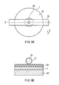
- Fig. 1 is a diagram illustrating a chemisorptive thin film formation step for producing a monomolecular film on a substrate in accordance with Working Example 1 of the present invention.
- Figs. 2A to 2C are diagrams schematically illustrating states of the chemisorptive thin film in Working Example 1 of the present invention.
- Fig. 2A is a diagram of the monomolecular film before the orientation treatment.
- Fig. 2B is a diagram illustrating the monomolecular film after the orientation treatment.
- Fig. 2C is a diagram illustrating the monomolecular film after crosslinking.
- Figs. 3A to 3C are conceptual diagrams illustrating how the coating is formed in Working Example 1 of the present invention.
- Fig. 3A illustrates how polymerizable liquid crystal molecules are formed randomly.
- Fig. 3B illustrates the state of the polymerizable liquid crystal molecules after the orientation treatment.
- Fig. 3C illustrates the state of the polymer liquid crystal molecules after polymerization.
- Fig. 4 is a conceptual diagram showing how optical information is recorded on the optical recording film of Working Examples 1 to 4 of the present invention.
- Figs. 5A to 5E are diagrams schematically illustrating variations of the recording regions formed on the optical recording medium in accordance with Embodiment 1 of the present invention.
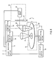
- Fig. 6 is a conceptual diagram showing an example of an information recording/reproducing apparatus in accordance with Working Example 4 of the present invention.
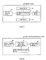
- Fig. 7 is a conceptual diagram showing an example of a computer system using an optical recording medium in accordance with Working Example 5 of the present invention.
- Fig. 8 is a conceptual diagram showing an example of a video recording/reproducing system using an optical recording medium in accordance with Working Example 6 of the present invention.
- Figs. 9A and 9B illustrate a method for rubbing a polyimide film in Working Example 2 of the present invention.
- Fig. 9A is a plan view illustrating a method for rubbing with a rubbing roll
- Fig. 9B is a cross-sectional view taken from the right illustrating the method for rubbing with a rubbing roll.
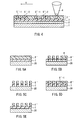
- Figs. 10A and 10B are conceptual diagrams showing, at the molecular level, a cross-sectional and a top view of the medium on which optical information has been recorded on an optical recording medium according to Working Example 3 of the present invention.
- Fig. 10A is a cross-sectional conceptual diagram of the medium on which optical information has been recorded.
- Fig. 10B is a conceptual diagram of the medium on which optical information has been recorded.
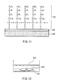
- Fig. 11 is a cross-sectional view schematically illustrating a write-once optical recording film in accordance with Working Example 7 of the present invention.
- Fig. 12 is a schematic diagram illustrating a method for manufacturing (film manufacturing step) a write-once optical recording film in accordance with Working Example 7 of the present invention.
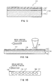
- Fig. 13 is a cross-sectional view schematically showing an optical recording medium in accordance with Working Example 9 of the present invention.
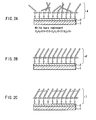
- Figs. 14A to 14B are diagrams illustrating a recording method for an optical recording medium in accordance with Working Example 9 of the present invention.
- Fig. 14A is a schematic diagram illustrating the recording method.
- Fig. 14B is a plan view schematically illustrating the recorded state.
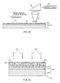
- Fig. 15 is a schematic diagram illustrating a reproduction method for an optical recording medium in accordance with Working Example 9 of the present invention.
- Fig. 16 is a schematic cross-sectional view illustrating another recording method for an optical recording medium in accordance with Working Example 9 of the present invention.
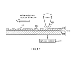
- Fig. 17 is a schematic diagram illustrating a reproduction method for an optical recording medium in accordance with Working Example 10 of the present invention.
- Fig. 18 is a schematic diagram illustrating the configuration of an information recording/reproducing apparatus in accordance with Working Example 11 of the present invention.
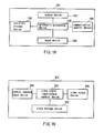
- Fig. 19 is a schematic diagram illustrating the configuration of a computer system in accordance with Working Example 12 of the present invention.
- Fig. 20 is a schematic diagram illustrating the configuration of a video signal recording/reproducing system in accordance with Working Example 13 of the present invention.
- Fig. 21 is a diagram illustrating a method for evaluating the orientation of the molecules constituting the optical recording film in accordance with Working Example 14 of the present invention.
- chemisorptive thin film refers to a thin film, in which a surface adsorbing agent having reactive groups, such as chlorosilyl groups alkoxysilyl groups, on its molecule ends is used to cause e.g. a dehydrochlorination reaction or dealcoholization reaction between the reactive groups and active hydrogen on the substrate surface, thus covalently bonding the surface adsorbing molecules to the substrate surface.
- a surface adsorbing agent having reactive groups such as chlorosilyl groups alkoxysilyl groups
- orientation regulating force of the chemisorptive thin film is utilized to orient the polymerizable molecules on the chemisorptive thin film.
- orientation regulating force refers to a force that automatically orients the polymerizable molecules that are formed on top of the chemisorptive thin film and are influenced by the orientation of the chemisorptive thin film.
- the chemisorptive thin film can be a monomolecular film or a polymer film.
- the molecules constituting the chemisorptive thin film with orienting properties is a monomolecular thin film
- the molecules constituting the chemisorptive thin film are aligned orderly, tilted in a certain direction.
- There are gaps between neighboring molecules constituting the chemisorptive thin film and when the shape of the polymerizable molecules conforms to these gaps, they can be fitted into these gaps.
- the molecules constituting the chemisorptive thin film are tilted in a predetermined direction, so that also the polymerizable molecules fitted into the gaps are tilted in a predetermined direction.
- the polymerizable molecules are linked to one another by polymer coupling.
- the polymerizable molecules are fixed while tilted in a certain direction and aligned orderly, so that it is possible to provide an optical recording film with high uniformity.
- the chemisorptive thin film having the above-described orienting function is a polymer film, then the polymer absorbs the irregularities of the layer below it, so that an optical recording film with superior flatness can be provided.
- the monomolecular film or polymer film is made of molecules having photosensitive groups, and by crosslinking, the photosensitive groups in the chemisorptive thin film are bonded to one another by crosslinking.
- the photosensitive groups are bonded by crosslinking, and the molecules are fixed, so that the orientation state of the molecules constituting the chemisorptive thin film is three-dimensionally stable.
- a chemisorptive thin film with superior orientation regulating force with respect to polymerizable molecules is attained.
- the photosensitive groups also can include double or triple bonds. Furthermore, the photosensitive groups also can be chalcone groups or cinnamate groups.
- the polymerizable molecules are polymerizable liquid crystal molecules.
- Polymerizable liquid crystal molecules can be aligned orderly in accordance with the orienting properties of the chemisorptive thin film, and the polymerizable liquid crystal molecules can be polymer bonded to one another in this state.
- a coating with uniform initial molecule orientation is achieved, so that an optical recording film with a high contrast between the written positions and non-written positions of the optical recording and with superior recording stability can be provided.
- “initial molecule orientation” means the orientation in which the polymerizable molecules are automatically oriented when they are formed on the chemisorptive thin film, influenced by the orientation chemisorptive thin film.
- the polymerizable liquid crystal molecules can have groups including double or triple bonds. If the polymerizable liquid crystal molecules have groups including double or triple bonds, then the groups easily can be polymerized to one another.
- the polymerizable liquid crystal molecules also can be photopolymerizable liquid crystal molecules. If the polymerizable liquid crystal molecules are photopolymerizable liquid crystal molecules, then the molecules easily can be polymerized to one another by irradiation with light.
- the polymerizable liquid crystal molecules include such a group, then they react more readily to light, so that by irradiating them with light, it is possible to orient the polymerizable liquid crystal molecules better with the desired tilt angle.
- Acryloyloxy groups are photopolymer groups, so that it is possible to perform the polymerization of the liquid crystal molecules reliably.
- both the portion denoted by the general formula (D) and the portion denoted by the general formula (E) include an acryloyloxy group
- the liquid crystal molecules can form at both ends crosslinking bonds with other liquid crystal molecules.
- a coating with superior orientation stability is attained.
- R 2 also can be a straight-chain or branched bivalent hydrocarbon group with a carbon number of 1 to 10. If R 2 is a straight-chain or branched bivalent hydrocarbon group with a carbon number of 1 to 10, then orientation in accordance with the orientation regulating force of the chemisorptive thin film becomes easier, so that a coating with superior orientation can be attained. More preferably, it is a straight-chain or branched bivalent hydrocarbon group with a carbon number of 1 to 3, which is even easier to orient.
- the group of polymerizable liquid crystal molecules is tilted in a predetermined direction on the chemisorptive thin film in accordance with the orienting properties of the chemisorptive thin film having an orienting function, and the polymerizable liquid crystal molecules are polymerized/fixed to one another.
- the polymerizable liquid crystal molecules are oriented uniformly and have superior orientation stability, so that an optical recording film with a high contrast between the written positions and non-written positions of the optical recording and with superior recording stability can be provided.
- the step of forming the chemisorptive thin film can be the formation of a monomolecular film in a dry atmosphere by bringing a chemisorptive solution including a silane-based chemisorptive substance having a photosensitive group and a non-aqueous organic solvent in contact with the substrate surface, and chemisorbing the molecules of the chemisorptive substance in the chemisorptive solution to the substrate surface.
- a chemisorptive thin film having gaps into which polymerizable molecules can be fitted between neighboring molecules constituting the chemisorptive thin film.
- the step of forming the chemisorptive thin film it is also possible to form a polymer film by applying a solution in which a polymer precursor has been dissolved on the substrate, followed by drying or heating the substrate, and curing the precursor. With this configuration, it is possible to form a flat polymer film despite irregularities in the substrate, so that an optical recording film with superior flatness can be manufactured.
- the above-mentioned orientation treatment step can be a polarized light orientation step of orienting by irradiating the substrate surface on which the chemisorptive thin film is formed with polarized light.
- the chemisorptive thin film surface can be oriented uniformly, so that a chemisorptive thin film having superior orientation regulating force can be attained and a uniform optical recording film can be manufactured.
- the orientation treatment step also can be a step of irradiating polarized light on the monomolecular film or the polymer film including film molecules having photosensitive groups to polymerize or crosslink the photosensitive groups, and thus orientation treating the monomolecular film and the polymer film.
- the photosensitive groups are bonded by crosslinking to one another, and the molecules are fixed, so that the orientation of the molecules constituting the chemisorptive thin film is stabilized three-dimensionally.
- it is possible to attain a chemisorptive thin film with superior orientation regulating force with respect to the polymerizable molecules so that it is possible to manufacture an optical recording film with which stable optical recording is possible.
- the polarized light that is irradiated can be UV light. This is because by using UV light, it is possible to bond the photosensitive groups to one another efficiently by crosslinking.
- the orientation treatment step also can be a step of orientation treating by rubbing the polymer film. When rubbing is used, then the orientation treatment of the chemisorptive thin film surface is facilitated.
- the polymerizable molecule orientation step it is also possible to use polymerizable liquid crystal molecules as the polymerizable molecules, and to use an organic solvent as the solvent in which the polymerizable liquid crystal molecules are dissolved.
- liquid crystal molecules are used, so that it is possible to achieve a uniform orientation due to the orientation regulating force of the chemisorptive thin film.
- the liquid crystal molecules easily can be bonded by crosslinking to one another, so that a coating with a three-dimensionally stable structure is attained, which makes it possible to manufacture an optical recording film on which optical information can be recorded stably.
- an organic solvent is used as the solvent in which the polymerizable liquid crystal molecules are dissolved, then the polymerizable liquid crystal molecules can be dissolved with high efficiency.
- organic solvent that is used has a boiling point of at least 100°C and at most 250°C. If the boiling point is lower than 100°C, then the solvent is removed from the substrate surface before the polymerizable liquid crystal molecules are sufficiently oriented, which is undesirable. On the other hand, if the boiling point is higher than 250°C, then solvent remains on the substrate surface even after the polymerizable liquid crystal molecules have been oriented, thus lowering the stability of the orientation, which is also undesirable.
- the coating formation step also can be a step of polymerizing the molecules by irradiating the polymerizable molecules with light. With this configuration, the photo-polymerization proceeds with high efficiency, so that an optical recording film can be manufactured with high efficiency.
- liquid crystal molecules for the polymerizable molecules.
- Such liquid crystal molecules easily can be polymerized by irradiation with light, because they are photo-polymerizable.
- the light that is irradiated is UV light. Irradiating UV light promotes photo-polymerization, so that the optical recording film can be manufactured with high efficiency.
- the sensitizing agent it is possible to use a substance that responds to UV light. Mixing a substance that responds to UV light, the photo-polymerization of the polymer film is promoted, so that the optical recording film can be manufactured with high efficiency.
- a substance containing -C 6 H 4 CO- has higher sensitivity to UV light.
- the medium substrate of the present invention includes at least a substrate, but it also can include a protective layer, a reflective film and other layers, as desired.
- the substrate can be made of metal, ceramic, glass or synthetic resin.
- the medium substrate also can be made of the substrate and a reflective layer including a metal that is layered on the substrate. With this configuration, it is possible to provide a reflective optical recording medium.
- the reflective layer can include aluminum. With this configuration, the reflectance of the light that is irradiated when writing optical information or reading out optical information is high, so that an optical recording medium is attained, which allows the reading and writing of optical information with high sensitivity. A preferable reflectance is about 97 to 98%.
- a further transparent protective layer on the reflective layer.
- a transparent protective layer is made of an inorganic substance, and it is even more preferable that this inorganic substance is SiO 2 or SiN x (stoichiometrically Si 3 N 4 , but the actual valence is not determined, so that x can be any suitable value).
- a reflective film is layered on both sides of the substrate, forming optical recording layers on both sides of the optical recording medium. With this configuration, it is possible to record double the optical information on one optical recording medium.
- the above-mentioned coating also can be provided over the entire surface of the chemisorptive thin film with orienting properties. Moreover, the coating can be provided partially on the chemisorptive thin film with orienting properties. It is possible to provide several kinds of films, in accordance with the intended use of the optical recording medium.
- the optical recording layer has at least one optical recording region.
- a means for providing a plurality of optical regions should provide a plurality of the above-mentioned coatings on the medium substrate.
- the medium substrate can be disk-shaped or tape-shaped. With such shapes, the shape is the same as for conventional optical recording media, so that it is possible to provide an optical recording medium that is easy to handle.
- the optical information regions can be arranged in concentric rings or in a spiral shape on the medium substrate.
- the optical recording regions it is also possible to form the recording layer by arranging on the medium substrate linear groups parallel to a direction that intersects at a predetermined angle with the longitudinal direction of a tape. With this configuration, the coating is arranged in the regions where optical information recording takes place, so that an optical recording medium is attained in which the reading and writing of optical information is easy.
- a group of polymerizable molecules which are aligned in a predetermined direction and with a predetermined tilt on the surface of a chemisorptive thin film, are fixed to one another by polymerization.
- the initial molecule orientation of the coating is changed.
- changing the initial molecule orientation of the coating means the cutting of polymer bonds between the polymerizable molecules by irradiation of light, or the changing of the initial alignment state having a predetermined direction and a predetermined tilt on the surface of the chemisorptive thin film by degrading molecules constituting the coating other than the polymer bonds. Furthermore, it also includes the loss of the initial orientation state by melting or the like, which is not brought about by cutting the polymer bonds between the polymerizable molecules nor by the degrading of the molecules constituting the film.
- What changes the initial molecule orientation of the film is the optical energy of the irradiated light or thermal energy converted from the optical energy.
- the reflective film is formed before the chemisorptive thin film formation step. It is also possible to form the reflective film by vapor deposition of a film including aluminum on the substrate surface.
- the metal reflective layer After the step of forming the metal reflective layer, it is also possible to form a transparent protective film made of an inorganic substance. Furthermore, it is also possible form the transparent protective film by any method selected from the group consisting of CVD, vapor deposition and sputtering using SiO 2 or SiN x as the inorganic substance.
- the chemisorptive thin film formation step it is also possible to form the chemisorptive thin film on at least one surface of the medium substrate on the entire surface. Furthermore, in the chemisorptive thin film formation step, it is also possible to form the chemisorptive thin film partially on at least one surface of the medium substrate. By changing the pattern of the formed chemisorptive thin film, it is possible to change the pattern of the coating formed on the chemisorptive thin film.
- the chemisorptive thin film formation step may include a step of producing a chemisorptive solution by dissolving in an non-aqueous organic solvent chemisorptive thin film constituting molecules having, in their molecules, a photosensitive group and a functional group that reacts with the medium substrate surface forming chemical bonds, and a step of bringing the chemisorptive solution in contact with a substrate having active hydrogen at its surface, thus chemisorbing the chemisorptive thin film constituting molecules to the substrate surface.
- the substrate surface on which the chemisorptive thin film is formed can be rinsed with a rinsing solution made of a non-aqueous organic solvent, and non-adsorbed chemisorptive thin film constituting molecules can be removed.
- a monomolecular film can be formed.
- the non-aqueous organic solvent used above is a dehydrated hydrocarbon solvent, carbon fluoride solvent, carbon chloride solvent or silicone solvent, because then there is only little water present, and moisture absorbance is inhibited.
- Non-adsorbed chemisorptive thin film constituting molecules can be present on the monomolecular film formed in the chemisorptive thin film formation step.
- the chemisorptive thin film is rinsed with the rinsing solution, then the non-adsorbed molecules are removed, and a high-quality monomolecular film can be formed, having many gaps for fitting the molecules constituting the polymer film.
- the substrate is a synthetic resin
- a step of introducing active hydrogen to the substrate surface is added, for example by subjecting the substrate surface before the chemisorptive thin film formation step to any of the methods selected from the group consisting of a plasma treatment, a corona treatment and a far UV light treatment. This is because, if the substrate is a synthetic resin, then it is necessary to have adsorbing groups for sufficient adsorption of the chemisorptive thin film forming molecules on the substrate surface.
- a step of forming a layer having active hydrogen on the substrate surface is also possible to add, before the chemisorptive thin film formation step, a step of forming a layer having active hydrogen on the substrate surface.
- the step of forming a layer having active hydrogen on the substrate surface also can be a step of forming a metal layer. Furthermore, this metal layer also can be used as a reflective layer. With this configuration, it is possible to simultaneously introduce active hydrogen to the surface of the medium substrate and form a reflective layer.
- hydroxyl groups For the active hydrogen present in the medium substrate surface, it is possible to use hydroxyl groups. Hydroxyl groups have a high reactivity with chemisorptive thin film constituting molecules, so that in this way a uniform chemisorptive thin film can be formed.
- the chemisorptive thin film formation step also can be a step of applying a solution in which a polymer has been dissolved in an organic solvent to the medium substrate surface, and after removing the solvent, heating and fixing the polymer to form a polymer film.
- the above-mentioned orientation treatment step can be carried out by orientation treating the entire chemisorptive thin film that has been formed. Or, the above-mentioned orientation treatment step also can be carried out by partially orientation treating the chemisorptive thin film that has been formed. It is also possible to change the pattern of the coating that is formed on the chemisorptive thin film by changing the orientation treatment parameters for the chemisorptive thin film.
- the orientation treatment step also can be a polarized light orientation step of an orientation treatment by irradiating polarized light on the medium substrate surface on which the chemisorptive thin film has been formed.
- the polarized light can be irradiated on the entire chemisorptive thin film, or it can be irradiated onto a portion of the chemisorptive thin film.
- the chemisorptive thin film can be a monomolecular film or a polymer film, which can be made of chemisorptive thin film constituting molecules including photosensitive groups, and it is also possible to irradiate polarized light in dots on the chemisorptive thin film while moving the medium substrate.
- the chemisorptive thin film is a monomolecular film, then the molecules at the polarized light irradiation position are arranged orderly, so that also the molecules constituting the polymer film are arranged orderly, and it is possible to form a recording format with high efficiency.
- the chemisorptive thin film is a polymer film, then the polymer film absorbs surface irregularities when the substrate surface has an irregular shape, so that it is possible to manufacture a flat optical recording medium
- the medium substrate is disk-shaped, then it is possible to irradiate polarized light in dots along the tracks formed on the medium surface while rotating the medium substrate. With this configuration, it is possible to orient the chemisorptive thin film regularly at a plurality of positions, so that it is possible to manufacture an optical recording medium provided with recording regions on which optical information can be recorded at high densities.
- the polarization direction of the polarized light irradiated in dots is the rotation direction of the medium substrate or a direction that intersects at right angles with the rotation direction.
- the polarization direction of the polarized light determines the orientation of the chemisorptive thin film, so that it also determines the orientation of the polymerizable molecules arranged on the chemisorptive thin film. Consequently, if the initial molecule orientation of the coating is changed by irradiating light when writing optical information, then the directions of reflected light, scattered light and transmitted light irradiated when reading the optical information are different in the changed regions and in the unchanged regions. Thus, it is possible to manufacture an optical recoding medium with which optical information can be read with high efficiency.
- the medium substrate is tape-shaped, then polarized light can be irradiated in dots along the tracks formed on the medium substrate while letting the medium substrate travel forward.
- polarized light can be irradiated in dots along the tracks formed on the medium substrate while letting the medium substrate travel forward.
- the orientation treatment step also can be a step of rubbing the polymer film while moving the medium substrate. If the medium substrate is disk-shaped, then it is also possible to rub the entire polymer film surface while rotating the medium substrate. If the medium substrate is tape-shaped, then it is also possible to rub the polymer film while letting the medium substrate travel forward. Furthermore, it is also possible to produce a tape-shaped optical recording medium by rubbing the polymer film while letting a wide medium substrate film travel forward and cutting the medium substrate after forming the polymer film. By rubbing, a chemisorptive thin film having an orienting function can be formed with high efficiency, so that it is possible to form an optical recording medium with high efficiency.
- the step of forming the coating it is possible to form a coating on the entire surface of the chemisorptive thin film by applying a solution in which polymerizable molecules have been dissolved on the entire surface of the chemisorptive thin film to bring the polymerizable molecules in contact with the chemisorptive thin film surface, removing the solvent, orienting the polymerizable molecules with the orientation regulating force of the chemisorptive thin film, and polymerizing the polymerizable molecules to one another.
- the step of forming the coating it is possible to form a coating on a portion of the chemisorptive thin film by applying a solution in which polymerizable molecules have been dissolved on the entire surface of the chemisorptive thin film to bring the polymerizable molecules in contact with the chemisorptive thin film surface, removing the solvent, orienting the polymerizable molecules with the orientation regulating force of the chemisorptive thin film, and polymerizing a portion of the group of polymerizable molecules to one another.
- the step of forming the coating it is also possible to form a coating partially by applying a solution in which polymerizable molecules have been dissolved on a portion of the chemisorptive thin film to bring the polymerizable molecules in contact with the chemisorptive thin film surface, removing the solvent, orienting the polymerizable molecules with the orientation regulating force of the chemisorptive thin film, and polymerizing the polymerizable molecules that have been applied on the chemisorptive thin film to one another.
- the coating it is also possible to form the coating by irradiating a group of polymerizable molecules with dot-shaped polarized light while moving the medium substrate.
- the medium substrate is disk-shaped, then it is also possible to irradiate polarized light in dots onto a group of polymerizable molecules along tracks while rotating the medium substrate. It is preferable that the polarization direction of the polarized light that is irradiated in dots is the rotation direction of the medium substrate or a direction that intersects at right angles with the rotation direction.
- the medium substrate is tape-shaped, then it is also possible to irradiate polarized light in dots onto a group of polymerizable molecules along tracks while letting the medium substrate travel forward.
- the reference light that is irradiated can be polarized light, and it is possible to detect the intensity change of a polarized light component only with an optical sensor, or to detect that light with an optical sensor after it has passed through a polarizer.
- the reference light that is irradiated can be polarized light, and it is possible to detect the intensity change of a polarized light component only with an optical sensor, or to detect that light with an optical sensor after it has passed through a polarizer.
- the emitted recording light also can be UV light. With this configuration, the beam diameter can be smaller when focusing the irradiated light.
- the wavelength of the emitted recording light and the wavelength of the emitted reference light can be the same.
- the recording light and the reference light can be irradiated using the same light source, so that the apparatus can be made smaller.
- the wavelength of the emitted recording light and the wavelength of the emitted reference light also can be different. With this configuration, the irradiation of the reference light has no influence on the initial orientation of the coating, so that it is possible to provide an information recording/reproducing apparatus with a stable recording state.
- the emitted recording light and the emitted reference light can both be laser light. With this configuration, the irradiated beams can be made sharp, so that it is possible to provide an information recording/reproducing apparatus with which high-density recording is possible.
- the irradiation area of the emitted recording light on the medium surface can be smaller than the irradiation area of the emitted reference light on the medium surface.
- the energy density of the emitted recording light can be made larger than the energy density of the emitted reference light. With this configuration, recorded information is not destroyed by irradiating the reference light, so that it is possible to provide an information recording/reproducing apparatus with stable recording information.
- the reference light emitting portion and the optical sensor can be provided on the same side of the recording medium, and the intensity change of a polarized component of the reflected reference light that has been reflected by the recording medium or the scatted reference light that has been scatted at the recording medium surface can be detected with the optical sensor.
- a reflection-type information recording/reproducing apparatus can be provided.
- a transmission-type information recording/reproducing apparatus can be provided.
- the information recording/reproducing apparatus can record and reproduce optical information with the following methods.
- One possible method is a method for recording and reproducing information on/from a write-once optical recording medium as described above, which includes a recording layer on which optical information can be recorded depending on whether an initial molecule orientation of a coating constituting the recording layer is changed or not by selectively irradiating focused light.
- information is recorded by selectively irradiating recording light onto the recording layer to write information elements depending on whether the initial molecule orientation of the coating constituting the recording film has been changed or not.
- Information is reproduced by selectively irradiating reference light that does not destroy the orientation of the polymer film on the recording layer, and detecting with an optical sensor, from the light that has passed through a polarizer, intensity changes in a polarized component of reflected light, transmitted light or scattered light of the reference light, which depend on whether the initial molecule orientation of the coating in the recording layer has been changed or not.
- the polarizer is arranged such that the polarization direction is parallel or perpendicular to the initial orientation of the coating.
- the polarization direction is parallel or perpendicular to the initial orientation of the coating.
- the polarizer is arranged such that its optical transmission axis is perpendicular to the initial orientation of the coating, then the intensity of the polarized component of the reflected light, the transmitted light and the scattered light becomes opposite to the above. Also in this case, it is possible to read optical information with high sensitivity.
- Another possible method is a method for recording and reproducing information on/from a write-once optical recording medium as described above, which includes a recording layer on which optical information can be recorded depending on whether an initial molecule orientation of a coating constituting the recording layer is changed or not by selectively irradiating focused light.
- information is recorded by selectively irradiating recording light onto the recording layer to write information elements depending on whether the initial molecule orientation of the coating constituting the recording film has been changed or not.
- Information is reproduced by selectively irradiating polarized light that does not change the initial molecule orientation of the coating as reference light on the recording layer, and detecting with an optical sensor intensity changes in a polarized component of reflected light, transmitted light or scattered light of the reference light, which depend on whether the initial molecule orientation of the coating in the recording layer has been changed or not.
- the reference light irradiated when reading the information oscillates in a direction that is parallel or perpendicular with respect to the direction in which the coating is oriented initially. If, at the portions that have maintained the initial orientation of the coating, the reference light oscillates in a direction that is parallel to the direction in which the coating is oriented initially, then the reference light is transmitted by the coating. In this case, if a reflective layer is provided, then the reflected light again is transmitted through the coating in the same oscillation direction. Therefore, the intensity of a polarized component of reflected light or transmitted light is large.
- Yet another possible method is a method for recording and reproducing information on/from a write-once optical recording medium as described above, which includes a recording layer on which optical information can be recorded depending on whether an initial molecule orientation of a coating constituting the recording layer is changed or not by selectively irradiating focused light.
- information is recorded by selectively irradiating recording light onto the recording layer to write information elements depending on whether the initial molecule orientation of the coating constituting the recording film has been changed or not.
- Information is reproduced by selectively irradiating polarized light that does not change the initial molecule orientation of the coating as reference light on the recording layer, and detecting with an optical sensor, from the light that has passed through a polarizer, intensity changes in a polarized component of reflected light, transmitted light or scattered light of the reference light, which depend on whether the initial molecule orientation of the coating in the recording layer has been changed or not.
- the irradiated light that is irradiated when reading information oscillates in a direction that is parallel or perpendicular with respect to the direction in which the coating is oriented initially.
- optical information can be read with high sensitivity.
- the reference light irradiated when reading information oscillates parallel or perpendicular with respect to the direction in which the coating is oriented initially, and the polarizer is arranged such that the optical transmission axis is parallel or perpendicular with respect to the direction in which the coating is oriented initially.
- the polarizer is arranged such that the optical transmission axis is parallel or perpendicular with respect to the direction in which the coating is oriented initially.
- the recording light that is irradiated when writing information and the reference light that is irradiated when reading information can be irradiated with different wavelengths.
- UV light can be irradiated as the recording light.
- information can be recorded by combining degraded portions and non-degraded portions obtained by classifying locally irradiated portions of an optical recording film as degraded portions and all other portions as non-degraded portions.
- the monomolecular thin film can be formed without using vacuum vapor deposition, so that it can be used as an inexpensive recording layer.
- information is recorded using a degradation reaction (irreversible reaction), so that the storing properties of the recorded information are favorable.
- substrate includes both a substrate alone as well as a substrate with a thin film formed on its surface.
- the degrading in the optical recording film is carried out by cleaving certain molecular bonds.
- information can be recorded with high precision, because the degraded portions are aligned by cleaving certain bonds.
- information can be recorded with very high precision.
- photodegradable functional group means a functional group that undergoes a degradation reaction through an excited state due to optical absorption. Using a molecule having such a functional group, the degradation reaction proceeds even at temperatures that are not very high, so that the substrate can be selected from a wider range.
- the photodegradable functional group it is possible to use any suitable functional group that can undergo a photodegradation reaction with UV light, such as a benzophenone residue, a benzyldimethylketal residue or a 1-hydroxy-cyclohexyl-phenylketone residue.
- a functional group that undergoes a degradation reaction under UV light fogging (unintended formation of degraded portions) will not occur when exposed to visible or infrared light during storage.
- “residue” refers to the molecular form after reaction. For example, it can be a functional group or the like obtained by removing one or more hydrogen atoms from a chemical compound.
- thermally degradable functional group refers to functional groups that undergo a degradation reaction utilizing the thermal effect of light. Using molecules having such a functional group, it is also possible to select the irradiated light without having to consider the absorbed wavelength, so that the recording light can be selected from a wider range.
- thermally degradable functional groups a benzoin residue or a benzopinacole residue can be used.
- the molecules constituting the thin film are straight-chain or rod-shaped molecules having a thermally degradable functional group or a photodegradable functional group on one molecule end, that the functional group on one molecule end is oriented in a direction pointing away from the substrate surface, and that the other end is covalently bonded to the substrate surface.
- straight-chain or rod-shaped molecules means molecules in which the group of atoms constituting the molecule is aligned in a straight line.
- the film constituting molecules are aligned as upright rods, and the thermally degradable functional groups or photodegradable functional groups are aligned at a predetermined position away from the substrate surface, so that the recording of information can be carried out with high precision.
- the dipole moment in the molecules is large, so that there is the advantage that the energy for recording or reproducing can be small.
- the light irradiation is constricted to a small region, then it is possible to record information at the molecule aggregate level (of several hundred to several thousand molecules), so that a recording medium with extremely high recording capacity can be provided.
- the functional group that is degraded when irradiated with light it is suitable to use a photodegradable functional group or a thermally degradable functional group. Specific examples of those functional groups are noted above.
- a chemisorptive group it is preferable to use at least one functional group selected from the group consisting of halosilyl groups, alkoxysilyl groups and isocyanatosilyl groups. These functional groups are fixed by covalent bonds to the substrate by an elimination reaction with functional groups including active hydrogen, such as hydroxyl groups exposed at the substrate surface, so that an optical recording film with superior peel-off resistance and adhesiveness can be formed.
- a substrate with exposed functional groups including active hydrogen for the substrate at which the functional groups reacting with the chemisorptive groups are exposed, it is preferable to use a substrate with exposed functional groups including active hydrogen.
- the functional groups including active hydrogen it is suitable to use hydroxyl groups.
- the surface of these substrates is hydrophilic, so that the optical recording film can be formed efficiently.
- the silica film etc. can be formed easily by CVD, vacuum vapor deposition or sputtering, for example. If there is little exposed active hydrogen in these substrates, then it is preferable to increase the exposed active oxygen by at least one surface treatment method selected from the group consisting of plasma treatment, corona treatment and far UV light treatment.
- the optical recording film formed on the substrate surface is rinsed with a non-aqueous organic solvent.
- a non-aqueous organic solvent it is possible to use a hydrocarbon solvent, a halogenized hydrocarbon solvent, a silicone-based hydrocarbon solvent, either alone or in a combination of two or more. With these solvents, the unreacted chemisorptive molecules can be removed reliably without reacting the optical recording film that has been formed.
- the substrate is an optical reflective substrate or an optically transmissive substrate. If it is an optically reflective substrate, then the optical recording medium is one in which reflected light is detected after irradiation with reproduction light (reflective optical recording medium).
- an optically reflective substrate it is preferable to use an optically reflective film such as a metal substrate, or to use a glass substrate, a ceramic substrate, a metal substrate or a synthetic resin substrate that has an optically reflective film formed on a suitable substrate surface. If a glass substrate, a ceramic substrate or a metal substrate is used, then the rigidity is high, so that an optical recording medium with superior durability can be provided. With a synthetic resin substrate, an optical recording medium with superior flexibility can be provided.
- a film including aluminum As the optically reflective film, it is preferable to use a film including aluminum as the optically reflective film. It is also possible to form an optically transmissive thin film on the uppermost surface of the substrate. If a silica film or a silicon nitride film is used for the optically transmissive thin film, then an optical recording medium with high recording density can be provided, because silica or silicon nitride films have a high density of exposed active hydrogen.
- the substrate is an optically transmissive substrate
- the optical recording medium is one in which after irradiation with reproduction light, the transmitted light is detected (transmissive optical recording medium).
- an optically transmissive substrate it is suitable to use an optically transmissive substrate such as a glass substrate, or to use an optically transmissive substrate with an optically transmissive thin film formed on one or both sides. If a silica film or a silicon nitride film is used for the optically transmissive thin film, then an optical recording medium with high recording density can be provided.
- optical recording medium has a plurality of information recording unit regions on which one information element can be written, depending on whether the film constituting molecules of the optical recording film are degraded or non-degraded, then an optical recording medium can be provided with which digital information can be recorded.
- information recording unit regions means regions in which one information element is recorded on the optical recording film.
- Information element refers to the elements when the information has been broken down to its minimal units (information units). More specifically, in conventional binary recording formats, in which the information units are single bits of information expressed by "0"s and "1"s, those "0"s and "1”s are the information elements. If the information recording unit regions are dot-shaped, then more digital information can be recorded.
- disk shapes, tape shapes and card shapes are preferable, because this allows the utilization of technology for optical recording media that is already in existence. If the substrate is disk-shaped, then it is preferable that the information recording unit regions on the optical recording film are aligned in concentric rings or in a spiral shape, because this allows high recording densities. On the other hand, in the case of tape-shaped or card-shaped substrates, it is preferable that the information recording unit regions of the optical recording film are aligned in parallel straight-chain groups at a predetermined angle with respect to the longitudinal direction of the substrate, because this allows high recording densities.
- a method in which a light-blocking member provided with light-passing portions corresponding to irradiated portions on the optical recording film, or a light-passing member provided with light-blocking portions corresponding to the portions other than the irradiated portions on the optical recording film is placed in opposition to the optical recording film, recording light is irradiated via this member onto the optical recording film, and the degraded portions corresponding to the irradiated portions are formed all together, then a large amount of information can be recorded in a short time.
- the recording and the reproduction of information can be performed with high precision, since the degrading is performed by cleaving certain portions in the molecules.
- a photodegradation reaction by optical irradiation or a thermal degradation reaction by optical irradiation is used when forming the degraded portions, then degraded portions can be formed in the optical recording film, and as a result, information can be recorded. If a photodegradation reaction is used, then the information recording can be carried out through a degradation reaction not involving high temperatures, so that the substrate can be selected from a broader range. On the other hand, if a thermal degradation reaction is used, then no consideration has to be given to the optical absorption wavelength with regard to the type of the optical recording film, so that the recording light can be selected from a broader range.
- UV light is used as the light for the recording, then the recording time (writing time) can be shortened, because of its high energy and its superior degradation efficiency. Furthermore, it can be constricted easily, so that recordings at high density are possible.
- the diameter of the recording light is smaller than the diameter of the reproduction light, then there is the advantage that the number of errors during recording can be decreased.
- the wavelength of the light that is irradiated from the recording light irradiation means is different from the wavelength of the light that is irradiated from the reproduction light irradiation means. This is, because if the recording light and the reproduction light have different wavelengths, then the recording of information during reproduction can be avoided. Furthermore, it is preferable that the recording light irradiation means irradiates UV light. It is also preferable that that the reproduction light irradiating means irradiates visible light or infrared light.
- the diameter of the light that is irradiated by the recording light irradiation means is smaller than the diameter of the light that is irradiated by the reproduction light irradiation means, then recording errors can be inhibited. Moreover, if the power density of the reproduction light is smaller than the power density of the recording light, then recording during reproduction can be avoided.
- computer system means a system that generally is provided with an arithmetic processing device having a main memory, an auxiliary storage device, an input device, an output device, and a communication control device controlling the communication among these devices, wherein upon a recording command entered from the input device, input information from the input device is transmitted as recording information signals of input information converted into electrical signals, via the arithmetic processing device to the auxiliary storage device, and recorded by the auxiliary storage device based on the transmitted recording information signals, and upon a reproduction command entered from the input device, the information recorded in the auxiliary storage device is read out as reproduction information signals from the auxiliary storage device, transferred via the arithmetic processing device to the output device, and reproduced by the output device based on the transferred reproduction information signals.
- video signal recording/reproducing system means a system that generally is provided with a video signal input/output control device controlling the input and the output of video signals, a video storage device, a video output device, and a control command input device for sending input/output control commands to the video signal input/output control device, wherein upon a recording command entered from the control command input device, video signals from an external video signal sender are transmitted via the video signal input/output control device to the video storage device, and the video information is recorded in the video storage device based on the transmitted video signals, and upon a reproduction command entered from the control command input device, the video information recorded in the video storage device is read out as reproduction video signals, transferred via the video signal input/output control device to the video output device, and reproduced by the video output device
- the present invention can provide an optical recording film made of an organic thin film formed by chemisorption and a method for manufacturing the same. Moreover, it can provide an inexpensive high-density write-once optical recording medium with which high-precision reading is possible. Furthermore, it can provide a computer system and a video signal recording/reproducing system using this write-once optical recording medium.
- FIG. 1 is a diagram illustrating the chemisorptive thin film formation step of producing a monomolecular film on the substrate.
- Figs. 2A to 2C schematically illustrate states of the chemisorptive thin film.
- Fig. 2A is a diagram illustrating the state of the monomolecular film before the orientation treatment.
- Fig. 2B is a diagram illustrating the state of the monomolecular film after the orientation treatment.
- Fig. 2C is a diagram illustrating the state of the monomolecular film after crosslinking.
- the chemisorptive thin film formation step is performed, which forms a chemisorptive thin film on the substrate 1.
- the material of the substrate and depending on the purpose of use, it is possible to use a variety of materials known in the art. Regarding their ease of handling, it is preferable to use a metal, a ceramic or a synthetic resin, for example. If the substrate is disk-shaped, then it is preferable to use a metal, such as aluminum or an aluminum alloy, glass, a ceramic, or polycarbonate, because of the rigidity of those materials. If the substrate is tape-shaped, then it is preferable to use a synthetic resin with superior flexibility, such as polyester. There is no particular limitation regarding the shape of the substrate.
- a disk-shaped substrate 1 is used.
- the substrate does not have to be disk-shaped, and it also can be tape-shaped or card-shaped.
- a reflective film 2 on a substrate 1, as for the optical recording medium.
- the reflective film 2 also can be a primer layer in accordance with the present invention.
- a chemisorptive solution 3 is prepared by dissolving in a non-aqueous organic solvent under a dry atmosphere a chemisorptive substance including a photosensitive group and a functional group (surface-active agent) that forms a chemical bond by reaction with the reflective layer 2. Then, the chemisorptive solution 3 is brought into contact with the substrate 1, and the molecules of the chemisorptive substance in the chemisorptive solution 3 are chemisorbed by the surface of the substrate 1.
- F chemical reaction
- the silane compound is highly active with respect to water, so that it is deactivated when the water content in the chemisorptive solution is too high.
- a non-aqueous organic solution which contains no active hydrogen groups, such as -OH groups.
- chemisorptive solution including a silane compound means a solution in which a silane compound has been dissolved in a solvent, but it also can be one in which a portion of the silane compound is not dissolved.
- An example of such a solution is a supersaturated chemisorptive solution.
- the compound (a1) includes a cinnamoyl group as the photosensitive group
- the compounds (a2) and (a3) include a chalconyl group as the photosensitive group.
- chlorosilane compound instead of the chlorosilane compound, it is also possible to use an isocyanate compound or an alkoxy compound, in which the chlorosilyl group has been replaced by an isocyanate group or an alkoxy group.
- the chlorosilane compound in (a1) to (a3) undergoes a dehydrochlorination reaction with the active hydrogen present at the primer surface, for example the hydrogen included in -OH groups, -COOH groups, -CHO groups, -NH 2 groups or >NH groups, forming covalent bonds.
- the alkoxy silane compound in (b1) to (b3) undergoes a dealcoholization reaction with the active hydrogen present at the primer surface, for example the hydrogen included in -OH groups, -COOH groups, -CHO groups, -NH 2 groups or >NH groups, forming covalent bonds.
- the isocyanate silane compound in (c1) to (c3) undergoes a deisocyanation reaction with the active hydrogen present at the primer surface, for example the hydrogen included in -OH groups, -COOH groups, -CHO groups, -NH 2 groups or >NH groups, forming covalent bonds.
- the film obtained by such an elimination reaction is also called a “chemisorptive film” or “self-assembling film.”
- suitable organic solvents for dissolving the chemisorptive substance include dehydrated hydrocarbon-based solvents, carbon fluoride solvents and silicone solvents, and solvents that can be used as petroleum-based solvents include petroleum naphtha, solvent naphtha, petroleum ether, petroleum benzine, isoparaffin, normal paraffin, decalin, industrial gasoline/kerosene, ligroin, dimethylsilicone, phenylsilicone, alkyl modified silicone and polyester silicone.
- a carbon fluoride solvent it is possible to use a fluorocarbon based solvent, Fluorinate (trademark by 3M Corp.) or Afluide (trademark by Asahi Glass Corp.), for example.
- solvents can be used alone or, if compatible solvents, in a mixture of two or more.
- silicone has a low water content, a low moisture absorbance, and easily dissolves chlorosilane compounds, so that it can prevent the direct contact between the chlorosilane compound and water. Consequently, with a chlorosilane compound and a solvent including silicone, it is possible to avert the adverse influence of hydrolysis due to the water components in the atmosphere during contact with the primer layer.
- the substrate is rinsed with a rinsing solution made of a non-aqueous organic solvent to remove the non-adsorbed chemisorptive thin film constituting molecules present on the substrate, then a chemisorptive thin film of the monomolecular film 4 can be formed.
- a suitable rinsing method are immersion and steam rinsing. With steam rinsing, all the excessive non-adsorbed chemisorptive thin film constituting molecules on the entire surface of the substrate 1 can be removed aggressively by the osmotic force of the steam, so that it is particularly effective.
- the non-aqueous organic solvent that is used can be the solvent used for the dissolving of the chemisorptive substance. If a chlorosilane compound, which is one type of silane compounds, is used for the chemisorptive substance, then it is preferable that chloroform or N-methyl-2-pyrrolidone is used for the rinsing solution. Chloroform not only can rinse monomers, it is also superior in the removing of chlorosilane polymers which are generated by the reaction of the chlorosilane compound with water.
- a polymer film can be formed as the chemisorptive thin film by applying a solution including the silane compound and a solvent to the substrate 1, initiating an elimination reaction with the active hydrogen at the substrate surface, then removing the solvent by drying, heating the substrate 1, and curing the precursor by hydrolysis.
- the thickness of the chemisorptive thin film is in the range of 0.5nm to 20nm.
- the chemisorptive thin film formed on the substrate 1 is subjected to an orientation treatment by photo-orientation (polarized light orientation step; see Fig. 2B).
- polarized light orientation step see Fig. 2B
- This chemisorptive thin film is a monomolecular film resulting from the chemisorption of aggregate groups of silane compound molecules, wherein the majority of the chemisorptive thin film constituting molecules are exposed orderly at the surface. Therefore, it has superior sensitivity with respect to polarized light, and it is possible to give the film an anisotropic orientation by irradiation of polarized light of low intensity.
- the thickness of the orientation film is that of a chemisorptive super-thin film, it is possible to read optical information with high sensitivity.
- the orientation treatment can be carried out with an optical orientation method.
- optical orientation is performed by the following method.
- Focused polarized UV light for example, light centered around the i-line of an extra-high pressure mercury lamp of 313 nm wavelength
- a polarizer onto the entire substrate in a direction that is substantially perpendicular to the substrate surface while rotating the substrate and while shifting the focused light in a radial direction, such that the polarization direction is parallel to the shifting direction of the substrate.
- the irradiation intensity of the polarized UV light can be in the range of for example 50 to 3000 mJ/cm 2 (wavelength: 365 nm). If the chemisorptive thin film is a polymer film with photosensitive groups, then the irradiation intensity of the polarized UV light can be in a range of 500 to 5000 mJ/cm 2 (wavelength: 365 nm), for example.
- this polarized light orientation step By performing this polarized light orientation step, it is possible to selectively photo-polymerize the photosensitive groups of the chemisorptive thin film constituting molecules in the chemisorptive thin film, and to bond the chemisorptive thin film constituting molecules at the surface of the substrate 1 by crosslinking along the substrate surface (see Fig. 2C).
- the monomolecular film 4 is oriented in a predetermined direction and turned into a chemisorptive thin film 7 with orienting properties.
- the chemisorptive thin film is a polymer film without photosensitive groups, then it can be subjected to an orientation treatment by a conventional method known in the art, such as a rubbing method.
- the chemisorptive thin film 7 with orienting properties has an orientation regulating force in the rubbing direction.
- a solution in which polymerizable molecules have been dissolved is applied to the surface of the chemisorptive thin film 7 with orienting properties, thus bringing the polymerizable molecules in contact with the chemisorptive thin film surface, the solvent is removed, and with the orientation regulating force of the chemisorptive thin film, the group of polymerizable molecules is aligned with a predetermined tilt in a predetermined direction on the surface of the chemisorptive thin film.
- Figs. 3A to 3C are conceptual diagrams illustrating how the coating of the present invention is formed.
- Fig. 3A illustrates how a group of polymerizable liquid crystal molecules is present on the chemisorptive thin film.
- Fig. 3B illustrates the state of the group of the polymerizable liquid crystal molecules after the orientation treatment.
- Fig. 3C illustrates the state of the monomolecular film after polymer bonding.
- polymerizable molecules there is no particular limitation regarding the polymerizable molecules, as long as they can be aligned with the orientation regulating force of the chemisorptive thin film 7 with orienting properties, but polymerizable liquid crystal molecules are preferable. Polymerizable liquid crystal molecules can be aligned uniformly on the chemisorptive thin film surface with the orientation regulating force of the chemisorptive thin film.
- the polymerizable liquid crystal molecules are dissolved in an organic solvent.
- the organic solvent preferably has a boiling point of at least 100°C and at most 250°C. Examples of suitable organic solvents are xylene and toluene.
- the group 5 of polymerizable liquid crystal molecules is present in a non-oriented state on the chemisorptive thin film 7 with orienting properties (Fig. 3A). Thereafter, the entire substrate 1, on which this film of photo-polymerizable liquid crystal molecules is formed, is heated, and the polymerizable liquid crystal molecules are put into an isotropic state. Then, cooling down slowly to room temperature, a film 5' is attained in which the group 5 of photo-polymerizable liquid crystal molecules has been oriented by the orientation regulating force of the chemisorptive thin film on the substrate (Fig. 3B).
- the cooling speed can be slower than 10°C/10min from 100°C to 25°C, for example. It is preferable that the film thickness of the polymerizable molecules is in the range of 10nm to 100nm.
- a coating formation step of forming a coating 5" is carried out, in which the molecules are polymerized or crosslinked.
- the coating formation step is a method that can polymerize the polymerizable molecules, and it preferably polymerizes the polymerizable molecules by irradiation of light onto the polymerizable molecules (Fig. 3C).
- the coating formation step it is preferable to use photo-polymerizable liquid crystal molecules as the polymerizable molecules.
- the molecules can be polymerized by irradiating light.
- UV light 6 promoting the polymerization is preferable.
- polymerizable liquid crystal molecules it is also possible to use the substance expressed by the above-noted general formula (A) mixed with functional acrylate monomers that are different from that substance. This promotes the polymerization reaction even more.
- a monofunctional acrylate such as methylmethacrylate, 2-ethylhexylacrylate, 2-hydroxyethylacrylate, 2-hydroxypropylacrylate, etc.
- a 2-functional acrylate such as 1,3-butanediol diacrylate, 1,4-butanediol diacrylate, 1,6-hexanediol diacrylate, diethyleneglycol diacrylate, neopentylglycol diacrylate, etc.
- a 3-functional acrylate such as pentaerythritol triacrylate, trimethylolpropane triacrylate, etc.
- a 4-functional acrylate such as pentaerythritol tetraacrylate, trimethylolpropane tetraacrylate, etc.
- a 5-functional acrylate such as dipentaerythritol pentaacrylate, etc.
- a substance that responds to UV light as a sensitizing agent.
- a sensitizing agent containing a -C 6 H 5 CO- group can be used. Adding several percent of such a sensitizing agent (for example IrgacureTM 651, 184, 500 by Japan Ciba-Geigy Corp. or KayacureTM BDMK, BP-100 by Nippon Kayaku Corp.) promotes the photoreaction, and shortens the polymerization time considerably.
- Optical information can be recorded on the optical recording film obtained as described above, depending on whether the initial molecule orientation of the coating has been changed by irradiating focused light selectively or not. More specifically, the optical information recording is carried out as shown in Fig. 4.
- Fig. 4 is a conceptual diagram showing how optical information is recorded on the optical recording film of the present invention.
- Focused light is irradiated as dots on the coating 5", while shifting the substrate 1.
- regions 5"-1 in which light has been irradiated on the coating 5"
- the initial molecule orientation of the coating is changed.
- regions 5"-2 in which light has not been irradiated on the coating 5"
- the initial molecule orientation of the coating stays the same. That is to say, with the optical recording film of the present invention, regions with a changed initial molecule orientation and regions with an unchanged initial molecule orientation are formed on the coating by selectively irradiating the coating with light that changes the initial orientation of the coating, thus writing the optical information.
- the optical recording medium of this embodiment is an example using the above-described optical recording film as an optical recording layer.
- the aspects that are different from the above-described optical recording film are explained with reference to Fig. 4.
- the optical recording medium of the present invention is made of a medium substrate and an optical recording layer.
- the medium substrate includes at least a substrate 1. Besides the substrate itself, the medium substrate also can include layers different from the optical recording layer, such as a reflective layer or a surface protection layer.
- the material of the substrate 1 the material used for the optical recording film in Embodiment 1 can be used.
- the medium substrate is made of a substrate 1 and a reflective layer 2 including a metal that is layered on this substrate, a reflective optical recording medium is obtained.
- the reflective layer can include at least aluminum. Examples of this include aluminum and aluminum alloys (such as aluminum containing silicon, for example).
- a reflective film 23 including such a metal can furnish active hydrogen to the surface of the medium substrate. Consequently, if a synthetic resin is used as the substrate, it also can function as a layer with active hydrogen.
- the method for layering the reflective layer 2 on the medium substrate there is no particular limitation to the method for layering the reflective layer 2 on the medium substrate, and any method known in the art can be used. For example, using vapor deposition, a thin and uniform layer can be formed, and is therefore preferable.
- a transparent protective layer made of an inorganic substance immediately after the metal reflective layer 2 has been formed. This prevents corrosion of the reflective film.
- an inorganic layer SiO 2 or SiN x can be used, for example.
- the method for forming the transparent protective film it is possible to use any method selected from the group consisting of CVD, vapor deposition and sputtering.
- active hydrogen can be introduced to the substrate surface by any method selected from the group consisting of plasma treatment, corona treatment and far UV treatment performed on the substrate surface before the chemisorptive thin film formation step.
- the source of active hydrogen present on the medium substrate surface it is possible to use hydroxyl groups.
- the coating 5" can be provided over the entire surface of the chemisorptive thin film 7 with orienting properties.
- Figs. 5A to 5E schematically illustrate how various types of recording regions are provided on an optical recording medium of the present invention. More specifically, the chemisorptive thin film 7 with orienting properties can be provided over the entire surface of the medium substrate 20, and the coating 5" can be provided on the entire surface of the chemisorptive thin film 7 (Fig. 5A).
- chemisorptive thin film over the entire surface of the medium substrate 20, but let only a portion 7 of this chemisorptive thin film have orienting properties, and to provide the coating 5" on this portion 7 of the chemisorptive thin film with orienting properties (Fig. 5B). It is further possible to provide a chemisorptive thin film 7 with orienting properties partially on the surface of the medium substrate 20, and to provide the coating 5" on this chemisorptive thin film 7 with orienting properties (Fig. 5C).
- chemisorptive thin film 7 with orienting properties partially on the surface of the substrate medium 20, and to provide the film made of polymerizable molecules on the entire surface of the medium substrate 20, but to orient only the coating 5" provided on the chemisorptive thin film (Fig. 5D).
- the coating 5" also can be provided partially on the surface of the chemisorptive thin film 7 with orienting properties.
- a method for providing the chemisorptive thin film 7 partially on the surface of the medium substrate 20 is to form a monomolecular film or a polymer film partially on the surface of the medium substrate, and to subject the monomolecular film or polymer film to an orientation treatment, for example.
- Another possibility is to provide the chemisorptive thin film on the entire surface of the medium substrate 20, and then to perform a partial orientation treatment by masking the chemisorptive thin film.
- a method for providing the coating 5" partially on the surface of the chemisorptive thin film can be, for example, as follows.
- the coating 5" can be formed by applying polymerizable molecules partially onto the chemisorptive thin film 7.
- the coating 5" can be formed by applying polymerizable molecules to the entire chemisorptive thin film, and partially subjecting it to an orientation treatment.
- the coating 5" functions as an optical recording region 19 of the optical recording layer.
- the medium substrate is disk-shaped or tape-shaped, then the following medium substrates can be obtained.
- the medium substrate is disk-shaped, and the coating 5" is provided in concentric rings or in a spiral shape along a track pattern on the medium substrate, then an optical recording film can be obtained in which optical recording regions are arranged in concentric rings or spiral shape on the medium substrate.
- the coating can be continuous and linear, or it can be formed of aligned dots.
- the medium substrate is tape-shaped, and the coating 5" is provided on the medium substrate in linear groups that are parallel to a direction intersecting at a predetermined angle with the longitudinal direction of the tape along a track pattern, then an optical recording medium can be obtained, in which the recording layer is formed by arranging the optical recording regions on the medium substrate in linear groups that are parallel to a direction intersecting at a predetermined angle with the longitudinal direction of the tape.
- the chemisorptive thin film is oriented by rubbing, then, in the case of a disk-shaped medium substrate, the entire surface of the polymer film can be rubbed while rotating the medium substrate. In the case of a tape-shaped medium substrate, the polymer film can be rubbed while letting the medium substrate travel forward. Furthermore, it is possible to produce a tape-shaped optical recording medium by rubbing the polymer film while letting a medium substrate film of a broad width travel forward, and cutting this medium substrate film after the chemisorptive thin film has been formed on the polymer film. Conversely, it is also possible to keep the medium substrate fixed and move or spin a rubbing roll. There is no particular limitation regarding the shape of the rubbing roll used for rubbing, and it is possible to use a cylindrical or a truncated cone-shaped rubbing roll, for example.
- Fig. 6 is a conceptual diagram showing an example of an information recording/reproducing apparatus in accordance with the present invention.
- the information recording/reproducing apparatus shown in Fig. 6 includes an information recording portion (not shown in the drawings) having an optical recording medium 12 manufactured as in Embodiment 2, a signal input/output portion 13, a recording light emitting portion 14, a reference light emitting portion 15, an information element detecting portion 16, a position control driving portion 17, and a control circuit portion 18.
- the optical recording medium is rotatively driven by rotative driving with the position control driving portion 17. In the example in Fig. 6, it is rotated in the Y-direction.
- an optical signal related to external recording information is transmitted from the signal input/output portion 13 to the recording light emitting portion 14.
- the recording light emitting portion 14 emits recording light selectively, in accordance with an information signal made of ON/OFF signals.
- the recording light emitting portion 14 includes a focusing device, which focuses the emitted recording light (as indicated by numeral 8).
- the recording light there is no particular limitation regarding the recording light, as long as it is light that changes the initial molecule orientation of the optical recording regions of the optical recording medium.
- An example of suitable recording light is UV light.
- optical information is written on the optical recording medium 12, by forming portions in which the initial molecule orientation of the optical recording regions has been changed and portions in which the initial molecule orientation of the optical recording regions has not been changed (Fig. 4).
- the reference light emitting portion 15 includes a focusing device, which focuses the emitted reference light (as indicated by numeral 29).
- the reference light there is no particular limitation regarding the reference light, as long as it is light that does not change the initial molecule orientation in the optical recording regions of the optical recording medium, but preferably it is polarized light.
- the intensity of a polarized component of the reflected light, transmitted light or scattered light of the reference light is changed depending on whether the initial molecule orientation has been changed or not.
- This intensity change is detected with the information element detecting portion 16.
- it is picked up with an optical sensor 22 through a polarizer 21.
- polarizer 21 it is possible to pick up intensity changes with the optical sensor 22 also without the polarizer 21.
- the polarizer 21 There is no particular limitation regarding the polarizer 21, and it is possible to use one of the polarizers known in the art, such as an ordinary polarization plate.
- the direction of the transmission axis of the polarizer is parallel or perpendicular to the orientation of the molecules of the coating, then it is possible to change the forward direction of the light with a beam splitter 23 such that the oscillation direction of the light does not change before it is incident on the polarizer.
- the detected result is converted into a predetermined electrical signal by the information element detecting portion 16.
- the electrical signal is outputted by the signal input/output portion 13 to an external detector (not shown in the drawings). With the external detector it is possible to detect the reproduced signal and thus to read information that has been recorded in the optical recording regions 18.
- the wavelength of the emitted recording light and the wavelength of the emitted reference light can be the same.
- the recording light emitting portion 14 and the reference light emitting portion 15 can be combined, so that a simpler information recording/reproducing apparatus can be provided.
- the recording light emitting portion 14 and the reference light emitting portion 15 have different configurations, then the recording light and the reference light can be irradiated at different wavelengths, so that it is possible to provide an information recording/reproducing apparatus with stable optical information recording, in which no changes of the orientation of the molecules occur during the reading of optical information.
- the recording light is UV light.
- both the emitted recording light and the emitted reference light as laser light.
- the surface area of the medium substrate irradiated with the emitted recording light can be made smaller than the surface area of the medium substrate irradiated with the emitted reference light. Thus, it is possible to reduce the number of read-out errors during reading.
- the energy density of the emitted recording light can be made larger than the energy density of the emitted reference light on the medium substrate.
- the orientation of the coating does not change during reading, so that an information recording/reproducing apparatus with stable optical information recording can be provided.
- the reference light emitting portion 15 and the optical sensor 22 can be provided on the same side of the surface of the recording medium 12. In this case, intensity changes in the reflection light of emitted reference light that is reflected by the recording medium 12 or the scattered light of emitted reference light that is scattered at the surface of the recording medium 12 are detected by the optical sensor 22.
- the recording medium 12 between the reference light emitting portion 15 and the optical sensor 22. In this case, changes in the intensity of transmission light of emitted reference light that is transmitted through the recording medium 12 are detected by the optical sensor 22.
- the polarizer 21 can be arranged such that its optical transmission axis is parallel or perpendicular to the initial orientation of the coating.
- initial orientation of the coating refers to the extended direction of the long axis of the molecules on the projection plane, when the polymerizable molecules, which are tilted in a predetermined direction on the chemisorptive thin film with orienting properties, are projected on the medium substrate. More specifically, it refers to the X-direction in Fig. 4.
- the irradiated polarized light can oscillate such that the polarization direction is parallel or perpendicular to the initial orientation of the coating.
- the irradiated polarized light can oscillate such that the polarization direction is parallel or perpendicular to the initial orientation of the coating.
- the polarizer can be arranged such that the optical transmission axis becomes parallel or perpendicular to the initial orientation of the coating.
- the control circuit portion 18 sends control signals to the position control driving portion 17, the recording light emitting portion 14, and the information element detecting portion 15, coordinating the movement of the medium substrate 20 with the emission position of the recording light and the emission position of the reference light.
- Fig. 7 schematically illustrates an example of a computer system using an optical recording medium in accordance with the present invention.
- the computer system 30 of this embodiment includes an arithmetic processing device 31 having a main memory, an auxiliary recording device 32 connected to the arithmetic processing device using the optical recording medium 12 of the present invention as an auxiliary memory, an input device 33 connected to the arithmetic processing device, an output device 34 connected to the arithmetic processing device and a control device 35 controlling the data communication between the various devices.
- "connected” refers to an operational connection, and not necessarily a physical connection or presence in the same physical location.
- the input information from the input device 33 is transmitted as recording information signals to the auxiliary recording device 32, through the arithmetic processing device 31.
- the optical recording medium is rotatively driven by the position control driving portion. During the information recording, the recording information signals are transmitted from the signal input/output portion to the recording light emitting portion.
- the recording light emitting portion selectively emits the recording light in correspondence to the information signal made of ON/OFF signals.
- the selectively emitted recording light writes recording information onto the optical recording medium, with portions where the initial molecule orientation of the optical recording regions has been changed, and portions where the initial molecule orientation of the optical recording regions has not been changed.
- the reference light emitting portion includes a focusing device, which focuses the emitted recording light.
- the reference light is preferably polarized light.
- the intensity of a polarized component of the reflected light, the transmitted light or the scattered light of the reference light varies depending on whether the initial molecule orientation has been changed.
- This intensity change is detected with an optical sensor through a polarizer.
- the detected result is then converted into a predetermined electrical signal.
- This electrical signal is outputted by the signal output portion and transmitted via the arithmetic processing device 31 to the output device 33. Based on the transmitted reproduction information signal, the information is then reproduced by the output device 34.
- Fig. 8 schematically illustrates an example of a video recording/reproducing system using an optical recording medium in accordance with the present invention.
- the video recording/reproducing system 40 of the present embodiment includes a video signal input/output control device 41 for controlling the input source and the output destination of the video signal, a video recording/reproducing device 42 using the optical recording medium of the present invention connected to the video signal input/output device, a video output device 43 connected to the video signal input/output control device, and a control command input device 44 connected to the video signal input/output device, which sends input/output control commands to the video signal input/output control device.
- “connected” refers to an operational connection, and does not necessitate a physical connection or presence in the same physical location.
- the input information from the video signal input/output device 41 is transmitted as a video information signal through the control command input device 44 to the video recording/reproducing device 42.
- the optical recording medium is rotatively driven by the position control driving portion.
- the video information signal is transmitted from the signal input/output portion to the recording light emitting portion.
- the recording light emitting portion selectively emits recording light in correspondence to the information signal made of ON/OFF signals.
- the selectively emitted recording light writes video information onto the optical recording medium, with portions where the initial molecule orientation of the optical recording regions has been changed, and portions where the initial molecule orientation of the optical recording regions has not been changed
- the reference light emitting portion includes a focusing device, which focuses the emitted reference light.
- the reference light is preferably polarized light.
- the intensity of a polarized component of the reflected light, the transmitted light or the scattered light of the reference light varies depending on whether the initial molecule orientation has been changed.
- This intensity change is detected with an optical sensor through a polarizer. Based on the detected result, the intensity of a polarized component is then converted into a predetermined electrical signal.
- This electrical signal is outputted by the signal input/output portion and transmitted via the control command input device 44 to the video input/output device 43. Based on the transmitted reproduction information signal, the information is then reproduced by the video reproduction device 42.
- a disk-shaped glass-substrate 1 was prepared, and after thoroughly rinsing and degreasing the substrate surface, aluminum including 2 mass% silicon was applied in a film thickness of about 500 nm by vapor deposition, thus forming a reflective film 2 (see Fig. 1).
- This compound was dissolved in an amount of about 1 mass% in dehydrated hexadecane (a non-aqueous organic solvent), thus preparing a chemisorptive solution.
- this chemisorptive solution 3 was filled into a solvent bath, and the glass substrate 1 on which the reflective layer 2 has been formed was immersed for about 1 hour in this solvent bath under a dry atmosphere (not more than 30% relative humidity). It should be noted that it is also possible to use a method of application instead of immersion. Then, the substrate 1 was retrieved from the solvent bath, rinsed with dehydrated n-hexane, removing the non-adsorbed chemisorptive molecules at the surface, and kept for a while in air including a certain moisture content.
- a monomolecular film 4 (of about 1.8 nm film thickness) was formed from the chemisorptive molecules (Fig. 2A).
- UV curable liquid crystal molecules as represented by the below formula (J) were prepared and dissolved in an amount of about 10 mass% concentration in xylene, yielding a polymerizable molecule solution.
- this polymerizable molecule solution was applied with a spinner on the chemisorptive thin film 7 in which the adsorbed molecules were oriented and fixed by crosslinking.
- the substrate was dried, forming a film (of about 1 ⁇ m film thickness) made of photopolymerizable liquid crystal molecules (see Fig. 3A).
- the substrate on which this film made of photopolymerizable liquid crystal molecules was formed was heated to 120°C, and the polymerizable molecules were turned into an isotropic state. After that, the substrate was cooled down slowly to room temperature, and a film was obtained in which the group 5' of photopolymerizable liquid crystal molecules was oriented by the orientation regulating force of the chemisorptive thin film 7 on the substrate (Fig. 3B). For this, a cooling speed of not more than about 10°C/10min was preferable. Moreover, that the photopolymerizable liquid crystal molecule group was oriented in a predetermined direction was confirmed by FTIR and a liquid crystal test cell orientation method.
- UV light was irradiated at about 300 mJ/cm 2 on the group 5' of oriented photopolymerizable liquid crystal molecules, and a coating 5" was formed, thus obtaining the optically oriented film (see Fig. 3C).
- active hydrogen could be introduced to the surface of the substrate 1 by subjecting the surface to a method selected from plasma treatment, corona treatment and far UV light treatment.
- metals and ceramics are rigid, they are superior as disk-shaped substrates.
- synthetic resins have superior flexibility, and it was found that they are suitable as tape-shaped substrates.
- the substrate surface was rinsed with a dehydrated hydrocarbon solvent such as dehydrated n-hexane, a fluorocarbon solvent such as Fluorinate (by 3M Corp.), a chlorocarbon solvent such as chloroform, or a silicone solvent such as a dimethyl silicone derivative, and non-adsorbed molecules could be rinsed away efficiently.
- a dehydrated hydrocarbon solvent such as dehydrated n-hexane
- a fluorocarbon solvent such as Fluorinate (by 3M Corp.)
- a chlorocarbon solvent such as chloroform
- silicone solvent such as a dimethyl silicone derivative
- a photosensitive polyimide resin (Trademark: RN-1194 by Nissan Chemicals Corp.) including a photoreactive functional group was dissolved in ⁇ -butyrolactam. This solution was applied in a film thickness of about 500 nm on a disk-shape glass substrate 1, similar to Working Example 1. The substrate was kept at 200°C for two hours, the polyimide resin was cured, and a polymer film was formed on the substrate 1.
- the polymer film was irradiated with polarized UV light by the same method as in Working Example 1, and an orienting force was imparted on the polymer film.
- the UV light was irradiated at 1 mJ/cm 2 .
- the polymer film itself is not oriented, so that as the chemisorptive thin film became thick, the contrast during read-out became weaker. It was found that the thickness of the chemisorptive thin film was preferably not more than 1/10 of the thickness of the coating.
- a rubbing treatment was carried out instead of the optical orientation of the polyimide film.
- Fig. 9 illustrates a method for rubbing the polyimide film.
- Fig. 9A is a plan view illustrating a method for rubbing with a rubbing roll
- Fig. 9B is a lateral view taken from the right illustrating the method for rubbing with a rubbing roll.
- a rubbing roll 25 is oriented in a diameter direction D relative to the substrate 1 such that it passes through the rotation center 24, and carries a rubbing cloth 27 by Rayon Corp.
- the substrate 1 is fixed on a turntable 28.
- the turntable 28 can be rotated by a rotation driving means not shown in the drawings. With the rubbing roll 25 fastened, the turntable 28 is rotated in a Z direction.
- the polyimide film 26 is rubbed and oriented in concentric rings.
- a coating film 5" was formed in the same manner as in Working Example 1 on the chemisorptive thin film, which has been oriented in this concentric ring-shape.
- An analysis as in Working Example 1 showed that the polymerizable liquid crystal molecules were bonded by crosslinking in an oriented arrangement.
- a sensitizing agent including a -C 6 H 5 CO- group (for example IrgacureTM 651, 184, 500 by Japan Ciba-Geigy Corp. or KayacureTM BDMK, BP-100 by Nippon Kayaku Corp.) as the substance that responds to UV light, promoted the photoreaction and shortened the polymerization time considerably.
- a sensitizing agent including a -C 6 H 5 CO- group (for example IrgacureTM 651, 184, 500 by Japan Ciba-Geigy Corp. or KayacureTM BDMK, BP-100 by Nippon Kayaku Corp.) as the substance that responds to UV light, promoted the photoreaction and shortened the polymerization time considerably.
- a chemisorptive film 7 with orienting properties was provided on the entire surface of a medium substrate, and a coating 5" was provided on the entire surface of this chemisorptive thin film 7 (Fig. 5A). Furthermore, a chemisorptive thin film was provided on the entire surface of a medium substrate, and subjecting a portion of the chemisorptive thin film to an orientation treatment, a coating 5" was provided only on those portions 7 of the chemisorptive thin film that had orienting properties (Fig. 5B). And, a chemisorptive thin film 7 was provided on the entire surface of a medium substrate, and a coating 5" was provided partially on the surface of the chemisorptive thin film (Fig. 5E).
- a chemisorptive thin film 7 with orienting properties was provided partially on the surface of a medium substrate, and a coating 5" was provided only on those portions 7 of the chemisorptive thin film that had orienting properties (Fig. 5C). Furthermore, a chemisorptive thin film 7 with orienting properties was provided partially on the surface of a medium substrate, and a film made of polymerizable molecules was provided on the entire surface of the medium substrate, but the oriented coating 5" was formed only on the chemisorptive thin film 7 (Fig. 5D).
- a disk-shaped glass substrate 1 was prepared, the surface of the substrate was thoroughly rinsed and degreased, and then aluminum including 2 mass% of silicon was applied in a film thickness of about 200 nm by vacuum vapor deposition, forming a reflective layer 2, thus producing a disk-shaped medium substrate.
- Figs. 10A and 10B are conceptual diagrams showing, at the molecular level, a cross-sectional and a top view of the medium on which optical information has been recorded on an optical recording medium according to this Working Example 3 of the present invention.
- FIG. 10A is a cross-sectional diagram of the medium on which optical information has been recorded.
- Fig. 10B is a diagram of the medium on which optical information has been recorded.
- regions 5b in which the initial molecule orientation has been changed and regions 5a in which the initial molecule orientation has not been changed, in correspondence with the ONs and OFFs of the digital signal. Due to this change of the initial molecule orientation, optical information could be recorded on the optical recording medium.
- the recording could be read out as follows.
- Weak focused visible light 29 (for example, wavelength: 530 nm; energy: 100 mJ/cm 2 at the secondary harmonic of a YAG (yttrium aluminum garnet) laser) was irradiated in accordance with a track pattern onto the regions 5a and 5b on the line C, while rotating the medium substrate in B direction.
- the intensity changes of the light of the same wavelength reflected back from the regions 5a and 5b on the track pattern were sensed through a polarizing plate arranged such that the polarization direction was perpendicular to the rotation direction of the medium substrate. At the region 5a where the initial molecule orientation had not been changed, almost no reflection light could be detected.
- a transparent protective film made of SiO x (stoichiometrically SiO 2 , but the actual valence is not determined, so that x can be any suitable value) or SiN x (stoichiometrically Si 3 N 4 , but the actual valence is not determined, so that x can be any suitable value) was formed by CVD, vapor deposition or sputtering. It was found that this not only made the substrate surface hydrophilic, but also attained a medium substrate with superior friction resistance and scratch resistance.
- the medium substrate is disk-shaped, and the optical recording regions are arranged in concentric ring-shape or spiral shape on the medium substrate, then optical information could be written or read out easily.
- the medium substrate is tape-shaped, and the optical recording regions are arranged on the medium substrate in linear groups parallel to a direction that intersects at a predetermined angle with the longitudinal direction of the tape, thus forming the recording layer, optical information could be written or read out easily.
- the writing of optical information was possible even when during the writing of optical information, the polarization direction of the irradiated dot-shaped polarized light was set to a direction intersecting perpendicularly with the rotation direction of the medium substrate.
- the writing of optical information was possible by irradiating polarized light in dots along a track pattern in a direction intersecting at a predetermined angle with the longitudinal direction of the tape while letting the tape travel forward.
- Fig. 6 is a conceptual diagram showing an example of an information recording/reproducing apparatus according to the present invention.
- the information recording/reproducing apparatus shown in Fig. 6 includes an information recording portion (not shown in the drawings) having an optical recording medium 12 manufactured as in Working Example 3, a signal input/output portion 13, a recording light emitting portion 14, a reference light emitting portion 15, an information element detecting portion 16, a position control driving portion 17, and a control circuit portion 18.
- the optical recording medium 12 is driven rotatively by the position control driving portion. During the recording of optical information, optical signals related to the external information to be recorded were transmitted from the signal input/output portion 13 to the recording light emitting portion 14.
- the recording light emitting portion 14 emitted, in form of dots, recording light 8 focused to a diameter of 0.5 ⁇ m, in accordance with information signals made of ON and OFF signals.
- UV light was irradiated as recording light at 1 J/cm 2 from a direction perpendicular to the substrate surface.
- optical information could be written onto the optical recording medium 12, with portions in which the initial molecule orientation of the optical recording regions were changed and portions in which the initial molecule orientation of the optical recording regions were unchanged.
- the intensity of the reflected light with the same wavelength reflected from the surface of the optical recording medium 12 was detected with an optical sensor 22 through a polarizing plate 21 whose polarization direction was arranged in a perpendicular direction with respect to the rotation direction of the medium substrate 12. At the regions that had not been irradiated with recording light, almost no reflection light could be detected, whereas at the regions that had been irradiated with recording light, about 1/3 of the irradiated light was reflected back, so that the optical recording information could be read out with high precision as the ONs and OFFs of a digital signal.
- the wavelength of the emitted recording light was the same as the wavelength of the emitted reference light.
- a simpler information recording/reproducing apparatus could be provided, because the recording light emitting portion 14 and the reference light emitting portion 15 can be combined.
- Laser light was used for both the emitted recording light and the emitted reference light. It was confirmed that this could improve the focusing precision of the recording light and the reference light.
- the area of the medium substrate surface that was irradiated with the emitted recording light was set to a smaller area than the area of the medium substrate surface that was irradiated with the emitted reference light. It was confirmed that this reduced the read-out errors during read-out.
- the energy density of the emitted recording light was set to be larger than the energy density on the medium substrate of the emitted reference light.
- an information recording/reproducing apparatus with stable optical information recording could be provided, because the orientation of the coating was not changed during read-out.
- the reference light emitting portion and the optical sensor were provided on the same side of the recording medium 12. In this case, intensity changes in the reflected light of emitted reference light that was reflected from the recording medium or of scattered light that was scattered at the surface of the recording medium were detected with the optical sensor.
- the polarizer was arranged such that its optical transmission axis was parallel or perpendicular to the initial orientation of the coating.
- polarized light was irradiated as the reference light, and the intensity change a polarized component of reflected light, transmitted light or scattered light of the reference light was detected with an optical sensor without a polarizer, then the irradiated polarized light was polarized such that its oscillation direction was parallel or perpendicular to the initial orientation of the coating.
- the irradiated polarized light could be polarized such that its oscillation direction was parallel or perpendicular to the initial orientation of the coating.
- the polarizer could be arranged such that its optical transmission axis was parallel or perpendicular to the initial orientation of the coating.
- a computer system 30 was produced including an arithmetic processing device 31 having a main memory, an auxiliary recording device 32 connected to the arithmetic processing device using the optical recording medium 12 of the Working Example 1 as an auxiliary memory, an input device 33 connected to the arithmetic processing device, an output device 34 connected to the arithmetic processing device and a control device 35 controlling the data communication between the various devices, as shown in Fig. 7.
- the auxiliary recording device 32 connected to the arithmetic processing device 31 using the optical recording medium 12 of the present invention as an auxiliary memory was primarily used as a memory for backups.
- a video recording/reproducing system 40 was produced including a video signal input/output control device 41 for controlling the input source and the output destination of a video signal, a video recording/reproducing device 42 using the optical recording medium 12 of Working Example 1 connected to the video signal input/output control device 41, a video output device 43 connected to the video signal input/output control device 41, and a control command input device 44 connected to the video signal input/output control device 41, which sends input/output control commands to the video signal input/output control device 41, as shown in Fig. 8.
- This video recording/reproducing system could record a TV broadcast of about 40 hours, and could be used as a home server instead of a VTR for home use equipped with a 100 GB recording capacity.
- An optical recording film 101 of this working example which was fixed by covalent bonding to an aluminum film 103 formed on the surface of a glass substrate 102, as shown in Fig. 11, was manufactured as follows. It should be noted that Fig. 11 shows that the film constituting molecules are oriented in the same direction, but they do not necessarily have to be oriented in the same direction and also can be oriented in different directions.
- a glass substrate 102 was prepared by machining the glass substrate 102 into a disk-shape of about 100 mm diameter and thorough rinsing, and applying Al including 2 mass% Si to the (entire) surface thereof by vacuum vapor deposition, forming an aluminum film 103 of about 500 nm thickness.
- This aluminum film 103 was naturally oxidized and had many hydroxyl groups (-OH groups) exposed at the surface. With such an aluminum film 103, a monomolecular optical recording film 101 with high molecular density can be formed.
- chemisorptive solution was prepared by dissolving chemisorptive molecules (straight-chain molecules) in dehydrated hexadecane in an amount of about 1 mass% concentration.
- the chemisorptive molecules can represented by the following formula (L), and include a chlorosilyl group (SiCl) which is a chemisorptive group and a benzophenone residue (C 6 H 5 COC 6 H 4 -: absorption peak at 254 nm) which is a functional group absorbing light of a specific wavelength and undergoing a degradation reaction.
- SiCl chlorosilyl group
- C 6 H 5 COC 6 H 4 - absorption peak at 254 nm
- the substrate 102 with the aluminum film 103 was immersed for about one hour in the chemisorptive solution 104 under a dry atmosphere of not more than 30% relative humidity, and the chemisorptive molecules were fixed by covalently bonding to the surface of the aluminum film 103 through a dehydrochlorination reaction between the chlorosilyl groups of the chemisorptive molecules and the hydroxyl groups at the surface of the aluminum film 103 (Fig. 11).
- the surface was rinsed with dehydrated n-hexane to remove remaining unreacted chemisorptive molecules, and then exposed to an atmosphere containing a certain moisture content, so that adjacent chemisorptive molecules were linked to one another by siloxane bonds.
- the chemisorptive molecules on the substrate have a chlorosilyl group at one end and are relatively hydrophilic, whereas the other end has a relatively water-repellent phenyl group (C 6 H 5 -), so that the benzophenone residues were covalently bonded aligned in a position away from the hydrophilic aluminum film 103.
- the optical recording film formed in this manner was irradiated from a direction normal to the substrate with light of 254 nm wavelength from an extra-high pressure mercury lamp focused to a diameter of about 1.2 ⁇ m as the recording light, in dots (points) at an irradiation density of 500 mJ/cm 2 .
- a benzophenone residue was used as the photodegradable functional group, but it was confirmed that an optical recording film on which optical recording is possible similarly can be formed using a benzyldimethylketal residue (absorption peak at 255 nm) or a 1-hydroxy-cyclohexyl-phenylketone residue (absorption peak at 332 nm) instead.
- chemisorptive molecules having a photodegradable functional group at their molecule end were used, but it is also possible to use chemisorptive molecules having a photodegradable functional group in the middle of the molecule chain.
- a glass substrate was used as the substrate, but the present invention is not limited to this, and it is also possible to use other kinds of substrates, such as a ceramic substrate, a metal substrate or a synthetic resin substrate.
- a substrate can be used in which hydrogen atoms (hydroxyl groups) are introduced by one of the usual surface treatments known in the art, such as plasma treatment, corona treatment or far UV light treatment.
- a film in which functional groups that can react with the chemisorptive groups are exposed such as a silica film or a silicon nitride film, on the surface of the substrate.
- the chemisorptive molecules were chemisorbed by immersing the substrate with the Al film in the chemisorptive solution, but there is no limitation to this method, and it is also possible to chemisorb the chemisorptive molecules by spraying the chemisorptive solution to the substrate with the Al film, for example.
- n-hexane dehydrated n-hexane was used, but favorable rinsing also can be performed using other hydrocarbon organic solvents, for example a fluorocarbon organic solvent such as "Fluorinate” (trademark by 3M) a chlorocarbon organic solvent such as chloroform or a silicone organic solvent such as dimethyl silicone.
- fluorocarbon organic solvent such as "Fluorinate” (trademark by 3M)
- chlorocarbon organic solvent such as chloroform
- silicone organic solvent such as dimethyl silicone.
- the optical recording film formed in this manner was irradiated from a direction normal to the substrate, with recording light of 425 nm wavelength (h line) of an extra-high pressure mercury lamp, focused to a diameter of about 1 ⁇ m, in dots at an irradiation intensity of 300 mJ/cm 2 .
- the chemisorptive molecules represented by the formula (M) constituting the optical recording film in Working Example 8 do not absorb light of 425 nm, so that different from the recording film of Working Example 7, it seems that a degradation reaction occurred due to local heating by the irradiation of light.
- Optical recording was also possible using an azo compound residue such as a 2-carbamoylazobisbutylonitrile residue or a 2,2'-azobisbutylonitrile residue instead of the benzophenone residue or the benzoin residue used in Working Examples 7 and 8.
- an azo compound residue such as a 2-carbamoylazobisbutylonitrile residue or a 2,2'-azobisbutylonitrile residue instead of the benzophenone residue or the benzoin residue used in Working Examples 7 and 8.
- a write-once optical recording medium 111 utilizes reflected light during reproduction (i.e. during read-out), and includes a substrate 114 with an optically reflective film (aluminum film) 113 formed on the surface of a glass substrate 112, and an optical recording film 115 in which an aggregate group of chemisorptive molecules is fixed by covalent bonding to the surface of the optically reflective film 113.
- This write-once optical recording medium 111 was manufactured as follows.
- the substrate 114 was prepared by forming the optically reflective film 113 made of Al including 2 mass% Si in a thickness of 200 nm on the surface of the disk-shaped glass substrate 112. Furthermore, a chemisorptive solution was prepared by dissolving the chemisorptive molecules represented by formula (L) in the same manner as in Working Example 7.
- the optical recording medium 111 was manufactured by forming the optical recording film 115 on the substrate 114, as in Working Example 7.
- the optical recording medium 111 obtained like this was irradiated intermittently from a direction normal to the optical recording film 115 at an irradiation intensity of 20 mW, as shown in Figs. 14A and 14B.
- This intermittent irradiation of light was performed in correspondence with the ONs of a digital signal (of ONs and OFFs), while rotating the optical recording medium (at a rotation velocity of 2400 rpm).
- dot-shaped degraded portions 116 were formed in the optical recording film 115 in correspondence to the ONs, and non-degraded portions 117 were formed in correspondence with the OFFs.
- the degraded portions 116 and the non-degraded portions 117 are information recording unit regions.
- infrared light (light of 780 nm wavelength), focused to a diameter of about 1.5 ⁇ m, was irradiated from a direction normal to the optical recording film 115 at an irradiation intensity of 1 mW, as the reproduction light (reference light, read-out light) on the optical recording medium on which a recording has been performed as described above.
- the optical recording medium was rotated at the same speed as during the recording.
- the irradiated infrared light was transmitted through the optical recording film 115, and the intensity of the light of the same wavelength that was reflected back by the optically reflective film 113 was detected with an optical sensor (infrared sensor) 122.
- an optical sensor infrared sensor
- numeral 123 denotes a half-mirror.
- the recording and reproduction of information was also possible when using, instead of the glass substrate, a ceramic substrate, a metal substrate or a synthetic resin substrate, or a substrate with an optically reflective film formed on one of these substrate.
- the recording and reproduction of information was similarly possible when using an optically reflective substrate that reflects the reproduction light, such as a metal substrate.
- an optically transmissive thin film with many exposed active hydrogens such as silica film or a silicon nitride film, on the surface of the optically reflective film. This increases the molecular density, so that an optical recording film with high recording density can be attained.
- an optical recording medium with even better anti-peeling properties is attained, because of the physical force due to the fact that the distance between the molecules is short, which acts in addition to the bonding force due to the covalent bonds.
- optically transmissive thin film on the surface of the optical recording film, to protect the optical recording film.
- the light was irradiated sequentially, but there is no limitation to this, and it is also possible to form the degraded portions in the optical recording film together by placing a light-blocking member 122 with light-passing portions 121 corresponding to the irradiation portions in opposition to the optical recording medium 111 with the optical recording film 115 formed on the substrate 114, and irradiating UV light 123 with a UV light irradiation means, as shown in Fig. 16.
- a metal substrate with through holes corresponding to the light-passing portions
- the write-once optical recording medium of this working example utilizes transmitted light when reproducing, and except that the substrate was made by forming not an optically reflective film but an optically transmitting thin film 133' made of silica on the surface of the disk-shaped glass substrate, the optical recording medium was manufactured in the same manner as in Working Example 9.
- the optical recording medium obtained like this was irradiated intermittently from a direction normal to the optical recording film at an irradiation intensity of 20 mW (Fig. 14).
- This intermittent irradiation of light was performed in correspondence with the ONs of a digital signal (of ONs and OFFs), while rotating the optical recording medium (at a rotation velocity of 2400 rpm).
- degraded portions were formed in the optical recording film in correspondence to the ONs, and non-degraded portions were formed in correspondence with the OFFs.
- infrared light (light of 830 nm wavelength), focused to a diameter of about 1.6 ⁇ m, was irradiated from a direction normal to the optical recording film 115 at an irradiation intensity of 1 mW, as the reproduction light (reference light) 121 on the optical recording medium on which a recording has been performed as described above.
- the optical recording medium was rotated at the same speed as during the recording.
- the intensity of the light of the same wavelength as the irradiated infrared light that was transmitted through the optical recording film 115 and the substrate 114 was detected with an optical sensor (infrared sensor) 122.
- the intensity of the light that was transmitted through the degraded portions was strong, whereas the intensity of the light that was transmitted through the non-degraded portions and reflected back was weak, so that it could be read as the ONs and OFFs of a digital signal.
- the recording and reproduction of information was similarly possible when using, instead of the glass substrate, another optically transmissive substrate, such as a synthetic resin substrate, transmitting the reproduction light, or using a substrate on which an optically transmitting film, such as a silica film or a silicon nitride film, is formed on the surface of the substrate.
- an optically transmitting film such as a silica film or a silicon nitride film
- an information recording/reproducing apparatus in accordance with this working example includes the optical recording medium 111 as manufactured in Working Example 9 as an optical recording medium 181, a signal input/output device 182, a UV light irradiation device 183 serving as a recording light irradiation means, an infrared light irradiation device 184 serving as a reproduction light irradiation means, an optical sensor (infrared sensor) 185 that can detect optical intensities serving as an information element detecting means, a medium driving apparatus 186 serving as an optical recording medium driving means, and a control circuit 187 for performing positioning control among these devices.
- numeral 188 denotes a half-mirror.
- UV light (of 254 nm wavelength) was irradiated from a UV light irradiation device 183 at a diameter of 1 ⁇ m and an irradiation intensity of 20 mW, based on a signal from the signal input/output device 182, and information was recorded by turning the irradiated portion of the optical recording film of the optical recording medium 181, which was rotated by the medium driving device 186 and the control circuit 187, into degraded portions.
- UV light of high energy was used as the light for the recording, so that the information could be recorded in a short period of time.
- the optical recording medium 181 on which the information was recorded was irradiated with infrared light (of 780 nm wavelength) from an infrared irradiation device 184 at a diameter of 1.5 ⁇ m and an irradiation intensity of 1 mW while rotating the optical recording medium at the same speed as during the recording, and the intensity of the infrared light reflected from the optically reflective film was detected with an optical sensor (infrared sensor) 185, and outputted to the signal input/output device 182.
- infrared light was used as the reproduction light, so that the recorded information was not destroyed.
- molecules including a photodegradable functional group were used, but it was similarly possible to record information using molecules having a thermally degradable functional group.
- the irradiation energy of the reproduction light was set to not more than one tenth of the irradiation energy of the recording light.
- the disk is rotated at the same speed, then the recording was not destroyed during the reproduction when the power density of the recording light was not more than one tenth of the power density of the recording light.
- the foregoing has been explained for the case that a reflective optical recording medium is used, however it was also possible to use an information recording/reproducing apparatus with a transmissive recording medium similarly.
- the optical sensor is of course disposed at a position that is reached by the transmitted light.
- the above-described information recording/reproducing apparatus is one that incorporates an optical recording medium, but it also can be one in which the optical recording medium is removable.
- a computer system 19 in accordance with this working example uses an information recording/reproducing apparatus of 10 gigabyte storage capacity, made of one optical recording medium manufactured as in Working Example 9, as an auxiliary storage device (auxiliary memory) 192, and is made by combining an output device (e.g. monitor) 193, an input device (e.g. keyboard) 194, as well as an arithmetic processing device 195 including a main memory and a communication control device 196 (e.g. personal computer including both).
- an output device e.g. monitor
- an input device e.g. keyboard
- arithmetic processing device 195 including a main memory
- a communication control device 196 e.g. personal computer including both.
- the optical recording medium is used together with another auxiliary memory and is used primarily as a memory for backups.
- a video signal recording/reproduction system 201 in accordance with this working example uses an information recording/reproducing apparatus of 100 gigabyte storage capacity, made of ten optical recording media manufactured as in Working Example 9, as video storage device 202, and a video signal recording/reproducing system (home server) replacing a VTR for home use with a recording capacity of 100 gigabyte is configured by connecting it to a video signal input/output device 203, a control command input device 204 and a video output device 205.
- liquid crystal cell 60 As shown in Fig. 21, sandwiching it with polarizing plates 67 and 68, irradiating light from the back side and observing it from the position denoted by numeral 70.
- the liquid crystal cell 60 is made by arranging glass plates 61 and 63 on which the molecule films 62 and 64 constituting optical recording films are formed with the molecule films constituting optical recording films on the inner side, sealing with an adhesive 65 while maintaining a gap distance of 5 to 6 ⁇ m, and filling the inside with a liquid crystal composition 66 (nematic liquid crystal, for example "LC, MT-5087LA” by Chisso Corp.)
- a liquid crystal composition 66 nonematic liquid crystal, for example "LC, MT-5087LA" by Chisso Corp.
- the substrate on the rear side is not transparent, then one polarizing plate is arranged on the upper side, light is irradiated from the surface, and the reflected light is observed.
Landscapes
- Chemical & Material Sciences (AREA)
- Engineering & Computer Science (AREA)
- Nanotechnology (AREA)
- Crystallography & Structural Chemistry (AREA)
- Physics & Mathematics (AREA)
- General Physics & Mathematics (AREA)
- Condensed Matter Physics & Semiconductors (AREA)
- Materials Engineering (AREA)
- Composite Materials (AREA)
- Mathematical Physics (AREA)
- Theoretical Computer Science (AREA)
- Optical Record Carriers And Manufacture Thereof (AREA)
- Optical Recording Or Reproduction (AREA)
Applications Claiming Priority (4)
| Application Number | Priority Date | Filing Date | Title |
|---|---|---|---|
| JP2001053400 | 2001-02-28 | ||
| JP2001053400 | 2001-02-28 | ||
| JP2001097834 | 2001-03-30 | ||
| JP2001097834 | 2001-03-30 |
Publications (2)
| Publication Number | Publication Date |
|---|---|
| EP1237155A1 true EP1237155A1 (fr) | 2002-09-04 |
| EP1237155B1 EP1237155B1 (fr) | 2007-11-14 |
Family
ID=26610249
Family Applications (1)
| Application Number | Title | Priority Date | Filing Date |
|---|---|---|---|
| EP20020004522 Expired - Lifetime EP1237155B1 (fr) | 2001-02-28 | 2002-02-27 | Feuille pour enregistrement optique, procédé pour sa fabrication, support d' enregistrement optique, procédé pour sa fabrication, procédé d' enregistrement optique, appareil d'enregistrement/reproduction d' information, procédé de reproduction/enregistrement d' information, système d' ordinateur et système d' enregistrement/reproduction de signaux vidéo |
Country Status (4)
| Country | Link |
|---|---|
| US (1) | US6686017B2 (fr) |
| EP (1) | EP1237155B1 (fr) |
| CN (1) | CN100409336C (fr) |
| DE (1) | DE60223435T2 (fr) |
Families Citing this family (12)
| Publication number | Priority date | Publication date | Assignee | Title |
|---|---|---|---|---|
| JP3937767B2 (ja) * | 2001-02-28 | 2007-06-27 | 富士ゼロックス株式会社 | 光書込装置 |
| US7078083B2 (en) * | 2001-05-29 | 2006-07-18 | Matsushita Electric Industrial Co., Ltd. | Optical recording film, method for manufacturing the same, optical recording medium, information recording/reproducing device, computer system and video signal recording/reproducing system |
| WO2004001756A1 (fr) * | 2002-06-21 | 2003-12-31 | Seagate Technology Llc | Composant de lecteur de disques a monocouches auto-assemblees |
| JP5076593B2 (ja) * | 2007-03-29 | 2012-11-21 | 富士ゼロックス株式会社 | 光記録装置、光記録方法、及び画像表示装置 |
| TWI335029B (en) * | 2007-04-11 | 2010-12-21 | Ind Tech Res Inst | System for recording and reproducing holographic storage which has tracking servo projection |
| KR101644046B1 (ko) * | 2009-05-07 | 2016-08-01 | 삼성디스플레이 주식회사 | 액정 표시 장치 |
| KR20120113651A (ko) * | 2009-12-22 | 2012-10-15 | 파나소닉 주식회사 | 광 디스크 장치, 광 디스크 제어 방법 및 집적 회로 |
| JP2019520479A (ja) * | 2016-06-02 | 2019-07-18 | ザ リージェンツ オブ ザ ユニバーシティー オブ カリフォルニア | 有機フリーラジカルを用いた極薄金属ナノワイヤの合成 |
| CN110177669B (zh) * | 2017-02-02 | 2020-12-15 | 东丽株式会社 | 纤维增强塑料的制造方法 |
| WO2018195479A1 (fr) * | 2017-04-21 | 2018-10-25 | Verdant Lighting Technology, Inc. | Système d'éclairage à diodes électroluminescentes |
| EP3844799A4 (fr) * | 2018-08-27 | 2022-05-25 | Versum Materials US, LLC | Dépôt sélectif sur des surfaces contenant du silicium |
| CN113221196B (zh) * | 2021-05-13 | 2025-02-14 | 西藏熙安信息技术有限公司 | 一种利用纳米技术进行信息加密读写、解密及擦除方法 |
Citations (6)
| Publication number | Priority date | Publication date | Assignee | Title |
|---|---|---|---|---|
| EP0445534A1 (fr) * | 1990-02-05 | 1991-09-11 | Matsushita Electric Industrial Co., Ltd. | Procédé pour la préparation d'un film monomoléculaire organique |
| JPH03229711A (ja) * | 1990-02-05 | 1991-10-11 | Matsushita Electric Ind Co Ltd | 高配向性共役ポリマーの製造方法 |
| US5324548A (en) * | 1988-08-05 | 1994-06-28 | Matsushita Electric Industrial Co., Ltd. | Method for making optical recording mediums |
| JPH07187897A (ja) * | 1993-12-27 | 1995-07-25 | Matsushita Electric Ind Co Ltd | 有機薄膜及びその製造方法 |
| US5489451A (en) * | 1991-11-30 | 1996-02-06 | Roehm Gmbh Chemische Fabrik | Reversibly crosslinked orientable liquid crystalline polymers |
| US5846452A (en) * | 1995-04-06 | 1998-12-08 | Alliant Techsystems Inc. | Liquid crystal optical storage medium with gray scale |
Family Cites Families (4)
| Publication number | Priority date | Publication date | Assignee | Title |
|---|---|---|---|---|
| JPS62162254A (ja) * | 1986-01-09 | 1987-07-18 | Nec Corp | 光記録読出方法 |
| JP3229711B2 (ja) | 1993-06-08 | 2001-11-19 | 花王株式会社 | 洗浄剤組成物 |
| JPH1020295A (ja) * | 1996-07-04 | 1998-01-23 | Dainippon Printing Co Ltd | 画像記録装置 |
| US7078083B2 (en) * | 2001-05-29 | 2006-07-18 | Matsushita Electric Industrial Co., Ltd. | Optical recording film, method for manufacturing the same, optical recording medium, information recording/reproducing device, computer system and video signal recording/reproducing system |
-
2002
- 2002-02-25 US US10/084,811 patent/US6686017B2/en not_active Expired - Fee Related
- 2002-02-27 DE DE2002623435 patent/DE60223435T2/de not_active Expired - Lifetime
- 2002-02-27 EP EP20020004522 patent/EP1237155B1/fr not_active Expired - Lifetime
- 2002-02-28 CN CNB021066019A patent/CN100409336C/zh not_active Expired - Fee Related
Patent Citations (6)
| Publication number | Priority date | Publication date | Assignee | Title |
|---|---|---|---|---|
| US5324548A (en) * | 1988-08-05 | 1994-06-28 | Matsushita Electric Industrial Co., Ltd. | Method for making optical recording mediums |
| EP0445534A1 (fr) * | 1990-02-05 | 1991-09-11 | Matsushita Electric Industrial Co., Ltd. | Procédé pour la préparation d'un film monomoléculaire organique |
| JPH03229711A (ja) * | 1990-02-05 | 1991-10-11 | Matsushita Electric Ind Co Ltd | 高配向性共役ポリマーの製造方法 |
| US5489451A (en) * | 1991-11-30 | 1996-02-06 | Roehm Gmbh Chemische Fabrik | Reversibly crosslinked orientable liquid crystalline polymers |
| JPH07187897A (ja) * | 1993-12-27 | 1995-07-25 | Matsushita Electric Ind Co Ltd | 有機薄膜及びその製造方法 |
| US5846452A (en) * | 1995-04-06 | 1998-12-08 | Alliant Techsystems Inc. | Liquid crystal optical storage medium with gray scale |
Non-Patent Citations (2)
| Title |
|---|
| DATABASE WPI Section Ch Week 199538, Derwent World Patents Index; Class J04, AN 1995-290207, XP002200521 * |
| PATENT ABSTRACTS OF JAPAN vol. 016, no. 001 7 January 1992 (1992-01-07) * |
Also Published As
| Publication number | Publication date |
|---|---|
| US6686017B2 (en) | 2004-02-03 |
| US20020119279A1 (en) | 2002-08-29 |
| EP1237155B1 (fr) | 2007-11-14 |
| CN1377037A (zh) | 2002-10-30 |
| DE60223435T2 (de) | 2008-09-18 |
| CN100409336C (zh) | 2008-08-06 |
| DE60223435D1 (de) | 2007-12-27 |
Similar Documents
| Publication | Publication Date | Title |
|---|---|---|
| EP1237155B1 (fr) | Feuille pour enregistrement optique, procédé pour sa fabrication, support d' enregistrement optique, procédé pour sa fabrication, procédé d' enregistrement optique, appareil d'enregistrement/reproduction d' information, procédé de reproduction/enregistrement d' information, système d' ordinateur et système d' enregistrement/reproduction de signaux vidéo | |
| EP0271900B1 (fr) | Méthode et appareil d'enregistrement optique | |
| KR100719431B1 (ko) | 광학 기록 매체, 및 광학 기록 매체를 이용하는 기록 및/또는 재생 장치 | |
| WO1996031876A1 (fr) | Support de memorisation optique a cristaux liquides avec echelles de gris | |
| EP1425739A1 (fr) | Memoire optique a liquide fluorescent et dispositif d'enregistrement/de lecture associe | |
| US5272552A (en) | Optical modulation device and method using modulation layer of helical polymer liquid crystal having a helical chiral smectic C phase | |
| US7078083B2 (en) | Optical recording film, method for manufacturing the same, optical recording medium, information recording/reproducing device, computer system and video signal recording/reproducing system | |
| JP2002357882A (ja) | 光記録膜、その製造方法、光記録媒体、その製造方法、光記録方法、情報記録再生装置、情報記録再生方法、コンピュータシステムおよび映像信号記録再生システム | |
| US20040190095A1 (en) | Optical recording medium and optical recording method | |
| WO2003005283A2 (fr) | Systemes multicouches combines de memoire optique et d'affichage a cristaux liquides, avec moyens d'enregistrement et de lecture d'informations | |
| KR20060052900A (ko) | 광 기록 매체용 콘텐트 정보층 | |
| JP2003051138A (ja) | 光記録膜とその製造方法、光記録媒体、情報記録再生装置、コンピュータシステム及び映像信号記録再生システム | |
| JP2006096811A (ja) | ハードコートフィルムおよび情報記録担体 | |
| JPH07507898A (ja) | 消去可能な光媒体 | |
| JPH0877605A (ja) | 光学的記録媒体 | |
| JPH01221284A (ja) | 情報記録媒体 | |
| JP4666379B2 (ja) | 偏光多重記録再生システム | |
| JPH07169121A (ja) | 光学的記録媒体 | |
| JPH06349121A (ja) | 光磁気記録媒体 | |
| JPH07302446A (ja) | 光記録媒体 | |
| JPS6052944A (ja) | 光磁気記録媒体 | |
| JPH0447632B2 (fr) | ||
| JPS63266647A (ja) | 記録再生装置及び記録再生方法 | |
| JPH01284828A (ja) | 記録方法、記録媒体及び記録装置 | |
| JPH02132655A (ja) | 光カード |
Legal Events
| Date | Code | Title | Description |
|---|---|---|---|
| PUAI | Public reference made under article 153(3) epc to a published international application that has entered the european phase |
Free format text: ORIGINAL CODE: 0009012 |
|
| AK | Designated contracting states |
Kind code of ref document: A1 Designated state(s): AT BE CH CY DE DK ES FI FR GB GR IE IT LI LU MC NL PT SE TR |
|
| AX | Request for extension of the european patent |
Free format text: AL;LT;LV;MK;RO;SI |
|
| 17P | Request for examination filed |
Effective date: 20020719 |
|
| AKX | Designation fees paid |
Designated state(s): DE FR GB |
|
| GRAP | Despatch of communication of intention to grant a patent |
Free format text: ORIGINAL CODE: EPIDOSNIGR1 |
|
| GRAS | Grant fee paid |
Free format text: ORIGINAL CODE: EPIDOSNIGR3 |
|
| GRAA | (expected) grant |
Free format text: ORIGINAL CODE: 0009210 |
|
| AK | Designated contracting states |
Kind code of ref document: B1 Designated state(s): DE FR GB |
|
| RAP1 | Party data changed (applicant data changed or rights of an application transferred) |
Owner name: MATSUSHITA ELECTRIC INDUSTRIAL CO., LTD. |
|
| REG | Reference to a national code |
Ref country code: GB Ref legal event code: FG4D |
|
| REF | Corresponds to: |
Ref document number: 60223435 Country of ref document: DE Date of ref document: 20071227 Kind code of ref document: P |
|
| ET | Fr: translation filed | ||
| PLBE | No opposition filed within time limit |
Free format text: ORIGINAL CODE: 0009261 |
|
| STAA | Information on the status of an ep patent application or granted ep patent |
Free format text: STATUS: NO OPPOSITION FILED WITHIN TIME LIMIT |
|
| 26N | No opposition filed |
Effective date: 20080815 |
|
| PGFP | Annual fee paid to national office [announced via postgrant information from national office to epo] |
Ref country code: FR Payment date: 20130301 Year of fee payment: 12 Ref country code: GB Payment date: 20130228 Year of fee payment: 12 Ref country code: DE Payment date: 20130220 Year of fee payment: 12 |
|
| REG | Reference to a national code |
Ref country code: DE Ref legal event code: R119 Ref document number: 60223435 Country of ref document: DE |
|
| GBPC | Gb: european patent ceased through non-payment of renewal fee |
Effective date: 20140227 |
|
| REG | Reference to a national code |
Ref country code: FR Ref legal event code: ST Effective date: 20141031 |
|
| REG | Reference to a national code |
Ref country code: DE Ref legal event code: R119 Ref document number: 60223435 Country of ref document: DE Effective date: 20140902 |
|
| PG25 | Lapsed in a contracting state [announced via postgrant information from national office to epo] |
Ref country code: FR Free format text: LAPSE BECAUSE OF NON-PAYMENT OF DUE FEES Effective date: 20140228 Ref country code: GB Free format text: LAPSE BECAUSE OF NON-PAYMENT OF DUE FEES Effective date: 20140227 Ref country code: DE Free format text: LAPSE BECAUSE OF NON-PAYMENT OF DUE FEES Effective date: 20140902 |