EP1237146A1 - Spannklaue zur Befestigung einer Fussmaschine an einer Bass-Drum - Google Patents
Spannklaue zur Befestigung einer Fussmaschine an einer Bass-Drum Download PDFInfo
- Publication number
- EP1237146A1 EP1237146A1 EP02004448A EP02004448A EP1237146A1 EP 1237146 A1 EP1237146 A1 EP 1237146A1 EP 02004448 A EP02004448 A EP 02004448A EP 02004448 A EP02004448 A EP 02004448A EP 1237146 A1 EP1237146 A1 EP 1237146A1
- Authority
- EP
- European Patent Office
- Prior art keywords
- clamping claw
- hoop
- clamp
- pedal
- clamping
- Prior art date
- Legal status (The legal status is an assumption and is not a legal conclusion. Google has not performed a legal analysis and makes no representation as to the accuracy of the status listed.)
- Granted
Links
- 210000000078 claw Anatomy 0.000 claims abstract description 62
- 238000009527 percussion Methods 0.000 claims abstract description 16
- 230000007246 mechanism Effects 0.000 claims description 8
- 238000000034 method Methods 0.000 claims description 4
- 239000004033 plastic Substances 0.000 claims description 4
- 230000002040 relaxant effect Effects 0.000 claims description 2
- 238000006073 displacement reaction Methods 0.000 claims 1
- 239000000463 material Substances 0.000 claims 1
- 230000000284 resting effect Effects 0.000 claims 1
- 239000002023 wood Substances 0.000 description 3
- 238000010276 construction Methods 0.000 description 2
- 238000011161 development Methods 0.000 description 2
- 230000018109 developmental process Effects 0.000 description 2
- 230000000694 effects Effects 0.000 description 1
- 239000013013 elastic material Substances 0.000 description 1
- 230000006870 function Effects 0.000 description 1
- 239000002184 metal Substances 0.000 description 1
- 239000002990 reinforced plastic Substances 0.000 description 1
- 230000035807 sensation Effects 0.000 description 1
Images


Classifications
-
- G—PHYSICS
- G10—MUSICAL INSTRUMENTS; ACOUSTICS
- G10D—STRINGED MUSICAL INSTRUMENTS; WIND MUSICAL INSTRUMENTS; ACCORDIONS OR CONCERTINAS; PERCUSSION MUSICAL INSTRUMENTS; AEOLIAN HARPS; SINGING-FLAME MUSICAL INSTRUMENTS; MUSICAL INSTRUMENTS NOT OTHERWISE PROVIDED FOR
- G10D13/00—Percussion musical instruments; Details or accessories therefor
- G10D13/10—Details of, or accessories for, percussion musical instruments
- G10D13/11—Pedals; Pedal mechanisms
Definitions
- the invention relates to a clamping claw for connecting a foot machine for percussion instruments with a section of a circular hoop one Percussion instruments, especially a bass drum. Furthermore concerns the invention a corresponding foot machine.
- Such pedals are used to quickly play a drummer's foot and precisely to the percussion instrument, for example a bass drum to transmit a hammer operated by a pedal of the foot machine.
- the foot machine is usually equipped with a hook or a bracket or which is firmly connected to the foot machine, on the hoop of the bass drum attached.
- brackets consist of an upper and lower one Clamp part to be mounted on the hoops. With every dismantling or assembly the bass drum must make this connection between the foot pedal and hoop loosened or clamped again.
- the object of the invention is a clamping claw a foot pedal for percussion instruments that is simple and easy-to-use connection to the hoop of a percussion instrument creates without the - also consisting of sensitive woods - Hoops both during assembly and especially in the clamp position to damage.
- the first part i.e. the upper part when mounted on a lower section of the bass drum
- points of contact arranged offset inward relative to the second part or lower part to rest on the hoop.
- This staggered arrangement the points of contact or the clamping points of the clamp parts, that despite the starting points on the curved inside or outside of the Hoop the clamping force of the clamp acts axially over the contact points. It is thus a tension and torsion free and consequently for the wood of the Tension-free clamping of the clamping claw reached.
- the first part or the upper part of the clip is opposite to that second part or the lower part of the bracket in its geometric extent formed smaller along the hoop to offset the points of contact to reach.
- the points of contact are elastic contact elements trained who automatically the respective in the tension state Adjust the radius of curvature of the outer and inner circumference of the bass drum.
- the Contact elements are preferably made of rubber or a rubber-elastic Plastic and counteract wear of the hoop.
- the clamping claw is independent of the foot machine clamped the hoop and then connected to the foot pedal. In this clamped state, the clamping claw can even with one Dismantling or building up the bass drum remains and only rarely has to do that Hoops are removed.
- Mutual tension and relaxation. or clamping the first part or upper part and the second part or The lower part of the clamp of the clamping claw is preferably by means of screw connections reached.
- there are preferably four Set screws are provided, two for the rough adjustment and two for the Fine adjustment, which in particular ensure that the bracket parallel to the Hoop is tightened.
- an adjustment of the clamping claw is also made possible with differently designed hoops, for example if this are of different thickness.
- Appropriate engagement means on the foot machine include a push rod, their head pointing towards the hoop of the percussion instrument, for example is spherical.
- the push rod is operated using a lever mechanism in the direction of the hoop and back and the clamping claw on the Foot machine attached.
- the foot pedal has between the pillar feet of the bearing base on a contact rod that extends between the two column feet.
- the clamping claw itself points to hers end faces of the upper and lower part of the Clamp an inward or concave recess, which is approximately is adapted to the circumference of the contact rod.
- the quick release comes the clamping claw with its bulging end face on the contact rod for support, which has the advantageous effect that the mounted on the bass drum Clamping claw within a certain angle around the contact bar can be swiveled and thus, if necessary, an inclination of the bass drum without tension can be caught. In this way, tension of the Clamping claw on the hoop avoided and damage to the wood counteracted.
- the curved end faces of the clamping claw are preferably provided with longitudinal grooves.
- the contact rod or axis of the foot pedal is covered with a rubber jacket envelops. Both features reinforce the advantageous gripping and Verschwenkfunktion.
- the independent tension claw mounted on the hoop of the bass drum.
- the spherical end of the push rod inserted into the correspondingly shaped recess of the clamping claw. in this connection the arched face of the clamping claw lies against the contact rod of the Foot pedal.
- the push rod is moved away from the clamping claw and onto it Way clamped the clamping claw against the foot machine.
- a foot machine 1 for percussion musical instruments shown in FIG. 1 it is a double foot machine with two Flail 2, 3 using a two-part foot pedal 4 with two different Actuating mechanisms 5, 6 are operated.
- the basic construction or stand construction 7 of the foot pedal 1 consists of a base plate 8 on which their end 8a pointing towards the bass drum 9 two upward approximately perpendicularly extending bearing columns 10, 11 are arranged.
- a reinforced plastic band 12a 12b which is arranged on a first shaft 13 via a bushing
- the left beater 3 via the rear pedal part 4b by means of a rod drive 14, which rotates a second shaft 15, is operated.
- clamping heads 16, 17 On two independently working shafts 13, 15 are clamping heads 16, 17 arranged, in each of which the flail 2, 3 over the lower end of a Shaft 18, 19 is held, with the impact pad at its upper end 20, 21 is arranged.
- Such a foot pedal 1 is connected via a clamping claw 22 on the circular hoop 23 of the bass drum 9 (only partially shown here) attached.
- pedals come in principle, for example single or double foot machines with or without drainage mechanism for a spaced foot pedal, in question that the invention Have engagement means and the quick release.
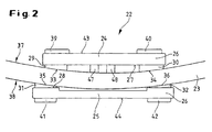
- the clamping claw 22 consists of a first plate-shaped part 24, here the upper part, and a second plate-shaped part 25, here the lower part, which together form a bracket 26.
- the top is shorter than the bottom, seen along the hoop, trained.
- the contact elements are made of rubber or a corresponding rubber-elastic plastic. These contact elements or Rubber pads with a curved surface 33, 34 and 35, 36 deform elastically at a state of tension and adapt to the radius of curvature of the inner or outer circumference 37, 38 of the hoop 23.
- More contact elements 39, 40 and 41 and 42 are on the top 43 of the top and attached to the underside 44 of the base to the top as well as the bottom to be able to use from both sides.
- the contact elements also stabilize 41, 42 or the lower rubber pads the clamping claw on the floor.
- the first part 24 or upper part and the second part 25 or lower part arranged on the hoop 23 so that they grasp it like a clamp. Then they are set using screws 45, 46 and 47, 48 braced. In the embodiment shown there are two Set screws 45, 46 for rough adjustment and two set screws 47, 48 for the fine adjustment is provided (see FIG. 3). It is particularly clear in FIG. 2 that that due to the offset contact points of the rubber pads a tension-free Clamp position of the clamping claw is reached.
- the clip 26 has the Clamping claw 22 has a recess 49 into which engaging means 50 of the foot pedal, here a rod 51 with a spherically shaped head 52, in engagement come.
- the design of the rod head 52 is not spherical limited; any other shape that will function with an appropriately shaped Recess 49 of the clamping claw 22 is also included in the invention.
- the recess 49 extends through the upper part and partly through the lower part.
- the respective end faces 53, 54 of the upper and lower part are processed so that a total of the entire Height of the clamping claw 22 results in a concave curvature or recess 55 (cf. here in particular Fig. 4).
- the bracket 26 of the clamping claw 22 is divided into the area 26b clamped to the hoop 23 and that of the Tire-pointing area 26a.
- the foot pedal has a fastening claw 22 designed in this way in addition to the engagement means 50 on a quick release 56.
- the quick release consists essentially of a reset mechanism for the rod 51, which will be discussed below.
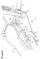
- the foot pedal is provided with a contact rod 60 or axis, which itself between the bearing columns 10, 11 and the bearing column feet 58, 59 of the foot machine extends.
- the contact rod 60 itself is made with a jacket 61a, b Surround rubber or an appropriate rubber-elastic material.
- the Contact rod 60 has a central passage opening 62 or a bore for the Push rod 51, the jacket 61a, b being interrupted at this point (see Fig. 5).
- the reset mechanism of the quick-release fastener 56 additionally includes the center (63) and at its end 64 pointing away from the clamping claw guided push rod.
- guides protrude from the base plate 8 65, 66 provided in the form of tabs with corresponding holes.
- the push rod 51 is released with its spherical end 52 Quick lock in the corresponding recess 49 of the clamping claw 22 inserted from above (see arrow in Fig. 3). This causes the clamping claw 22 with their curved end faces 53, 54 for contact with the contact rod 60 of the Pedal. This position is shown in FIG. 4.
- the lever 67 By pivoting the lever 67 and thus actuating the quick fastener 56, the push rod 51 and so that the head 52 moves back and the clamping claw 22 with respect to the foot machine 1 or the contact rod 60 clamped.
- the clamping claw 22 Because of the size of the coated contact rod 60 adapted bulge 55 of the end faces 53, 54 of the upper and lower part can the clamping claw 22 at a certain angle this rod swivel 60 or roll on the rod 60, so that inclined positions the bass drum 9 can be intercepted.
Landscapes
- Physics & Mathematics (AREA)
- Engineering & Computer Science (AREA)
- Acoustics & Sound (AREA)
- Multimedia (AREA)
- Auxiliary Devices For Music (AREA)
Abstract
Description
- Fig. 1
- einen Überblick über eine Fußmaschine für Perkussions-Musikinstrumente, die mittels einer Spannklaue an dem Spannreifen einer Bass-Drum befestigt ist;
- Fig. 2
- eine Seitenansicht einer Spannklaue in Klammerstellung auf einem Spannreifen, von der Bass-Drum gesehen;
- Fig. 3
- einen Ausschnitt einer Fußmaschine nach Fig. 1 mit einer Spannklaue in Klammerstellung auf einem Spannreifen während eines ersten Schritts des Befestigungsvorgangs;
- Fig. 4
- einen Ausschnitt einer Fußmaschine nach Fig. 1 mit einer Spannklaue während eines zweiten Schritts des Befestigungsvorgangs;
- Fig. 5
- einen Ausschnitt einer Fußmaschine nach Fig. 1 mit einer Spannklaue während eines dritten Schritts des Befestigungsvorgangs.
Claims (15)
- Spannklaue zur Verbindung einer Fußmaschine (1) für Perkussions-Instrumente mit einem Abschnitt eines kreisförmigen Spannreifens (23) eines Perkussions-Instrumentes, insbesondere einer Bass-Drum (9),
mit einer Klammer (26), die einen ersten Teil (24), einen zweiten Teil (25) sowie Mittel zum Verspannen und Entspannen des ersten (24) und zweiten Teils (25) gegeneinander aufweist,
wobei der erste Teil (24), der an die Innenseite des Spannreifens (23) angreift, gegenüber dem zweiten Teil (25), der an die Außenseite des Spannreifens (23) angreift, nach innen versetzt angeordnete Berührungspunkte zum Aufliegen auf dem Spannreifen aufweist. - Spannklaue nach Anspruch 1,
dadurch gekennzeichnet, daß der erste Teil (24) gegenüber dem zweiten Teil (25) in seiner geometrischen Ausdehnung längs des Spannreifens kleiner ausgebildet ist. - Spannklaue nach Anspruch 1 oder 2,
dadurch gekennzeichnet, daß die Berührungspunkte als Kontaktelemente (29-32) aus einem dem Innen- bzw. Außenumfang des Spannreifens (23) im Verspannungszustand anpaßbaren Material bestehen. - Spannklaue nach Anspruch 3,
dadurch gekennzeichnet, daß die Kontaktelemente (29-32) aus Gummi oder einem gummielastischen Kunststoff bestehen. - Spannklaue nach einem der Ansprüche 1 bis 4,
gekennzeichnet durch
Mittel zum lösbaren Verbinden der auf dem Spannreifen (23) montierten Klammer (26) mit der Fußmaschine. - Spannklaue nach Anspruch 5,
dadurch gekennzeichnet, daß der von dem Spannreifen (23) wegweisende Klammerteil eine Ausnehmung (49) aufweist, mit der ein Eingriffsmittel (50), das an der Fußmaschine (1) angeordnet ist, in Eingriff kommt. - Spannklaue nach einem der Ansprüche 1 bis 6,
dadurch gekennzeichnet, daß die Mittel zum gegenseitigen Verspannen und Entspannen des ersten und zweiten Teils der Klammer Schraubverbindungen (45-48) umfassen. - Spannklaue nach einem der Ansprüche 1 bis 7,
dadurch gekennzeichnet, daß die zur Fußmaschine weisenden Stirnseiten (53, 54) des ersten (24) und des zweiten Teils (25) der Klammer (26) eine konkav gewölbte Ausnehmung (55) aufweisen. - Spannklaue nach einem der Ansprüche 1 bis 8,
gekennzeichnet durch ,
ein plattenförmiges Oberteil als erstes Teil (24) mit zwei Kontaktelementen (29, 30) auf dessen an den Spannreifen (23) zur Auflage kommenden Unterseite (27),
ein plattenförmiges Unterteil als zweiten Teil (25) mit zwei Kontaktelementen (31, 32) auf dessen an den Spannreifen (23) zur Auflage kommenden Oberseite (28),
wobei die Ausnehmung (49) in dem von dem Spannreifen wegweisenden Klammerbereich (26a) entsprechend einem kugelartigen Ende einer Schubstange (51) von Eingriffsmitteln (50) der Fußmaschine (1) geformt ist, und dieses kugelartige Ende der Schubstange (51) zur lösbaren Verbindung in diese Ausnehmung (49) gelegt wird,
sowie mindestens zwei Schraubverbindungen (45-48), um das Oberteil gegenüber dem Unterteil in der Klammerstellung zu verspannen und zu justieren. - Fußmaschine zur Befestigung an einem Spannreifen eines Perkussions-Instrumentes mittels einer Spannklaue nach einem der Ansprüche 1 bis 9, umfassend
einen Lagersockel, an dem mindestens ein Schlegel (2,3) verschwenkbar gehalten wird, der mittels eines durch ein Pedal (4) bedienbaren Betätigungsmechanismusses (5, 6) bewegbar ist,
gekennzeichnet durch
Eingriffsmittel (50) für die Spannklaue (22), die an dem Spannreifen (23) lösbar montierbar ist, sowie einen Schnellverschluß (56) zum Verspannen der Eingriffsmittel (50) gegenüber der Spannklaue (22). - Fußmaschine nach Anspruch 10,
dadurch gekennzeichnet, daß die Eingriffsmittel (50) eine Schubstange (51) umfassen, deren zu dem Spannreifen (23) des Perkussions-Instrumentes weisender Kopf (52) kugelartig ausgeformt ist
und daß der Schnellverschluß (56) eine Hebelmechanik umfaßt, um die Schubstange in Richtung Spannreifen und zurück zu verstellen. - Fußmaschine nach Anspruch 10 oder 11,
dadurch gekennzeichnet, daß zwischen Säulenfüßen (58, 59) des Lagersockels eine Kontaktstange (60) montiert ist, die sich zwischen den beiden Säulenfüßen (58, 59) erstreckt, und an die die konkav gewölbte Ausnehmung (55) der Spannklaue beim Verspannvorgang gezogen wird und an der die Spannklaue (22) in einem bestimmten Winkel verschwenkbar ist. - Fußmaschine nach Anspruch 12,
dadurch gekennzeichnet, daß die Kontaktstange (60) mit einem Mantel (61a, 61b) aus Gummi oder einem gummielastischen Kunststoff umgeben ist. - Fußmaschine nach einem der Ansprüche 10 bis 13,
dadurch gekennzeichnet, daß die Schubstange (51) sich längs einer Bodenplatte (8) der Fußmaschine erstreckt und verschiebbar an der Bodenplatte (8) in mindestens einer Führung (65, 66) montiert ist sowie sich mit ihrem zu der Spannklaue hinweisenden Ende durch eine entsprechende Öffnung (62) in der Kontaktstange (60) erstreckt,
und daß die Schubstange (51) über eine an diese angreifende Exzenterscheibe (68), die mit einem Betätigungshebel (67) verbunden ist, über ein Verschwenken des Betätigungshebels (67) längs ihres Verschiebeweges verfahrbar ist, um den Schnellverschluß der Spannklaue (22) zu erreichen. - Fußmaschine nach einem der Ansprüche 10 bis 14 mit einer Spannklaue nach einem der Ansprüche 1 bis 9.
Applications Claiming Priority (2)
| Application Number | Priority Date | Filing Date | Title |
|---|---|---|---|
| DE10109945A DE10109945A1 (de) | 2001-03-01 | 2001-03-01 | Spannklaue und Fußmaschine für Perkussions-Instrumente |
| DE10109945 | 2001-03-01 |
Publications (2)
| Publication Number | Publication Date |
|---|---|
| EP1237146A1 true EP1237146A1 (de) | 2002-09-04 |
| EP1237146B1 EP1237146B1 (de) | 2006-07-05 |
Family
ID=7675978
Family Applications (1)
| Application Number | Title | Priority Date | Filing Date |
|---|---|---|---|
| EP02004448A Expired - Lifetime EP1237146B1 (de) | 2001-03-01 | 2002-02-27 | Spannklaue zur Befestigung einer Fussmaschine an einer Bass-Drum |
Country Status (3)
| Country | Link |
|---|---|
| US (1) | US6632990B2 (de) |
| EP (1) | EP1237146B1 (de) |
| DE (2) | DE10109945A1 (de) |
Families Citing this family (11)
| Publication number | Priority date | Publication date | Assignee | Title |
|---|---|---|---|---|
| US20060005689A1 (en) * | 2004-07-08 | 2006-01-12 | Fusamitsu Ito | Pedal coupling device and bass drum |
| US7262356B1 (en) * | 2006-04-18 | 2007-08-28 | Lukios Ii Charles Dean | Bass drum pedal hyper-beater |
| US7897858B1 (en) * | 2009-10-29 | 2011-03-01 | Tsun-Chi Liao | Drum rim clamping apparatus for a foot pedal hammer seat |
| DE102010046921B3 (de) * | 2010-09-29 | 2011-12-15 | Sonor Gmbh & Co. Kg | Fußmaschine von Perkussions-Instrumenten |
| US9240169B2 (en) | 2010-10-22 | 2016-01-19 | Drum Workshop, Inc. | Pivot supports for drum rim |
| US8330032B1 (en) * | 2010-10-22 | 2012-12-11 | Drum Workshop, Inc. | Pivot supports for drum rim |
| US10012261B2 (en) | 2011-09-26 | 2018-07-03 | Kenneth Alvin Jungeberg | Method and apparatus for releasably immobilizing an attachment to an external object |
| US9093053B2 (en) * | 2011-11-03 | 2015-07-28 | Kenneth Alvin Jungeberg | Arrestor for user operated devices |
| US9257106B2 (en) * | 2014-02-06 | 2016-02-09 | Ai-Musics Technology Inc. | Digital bass drum kick |
| US10504495B1 (en) | 2018-07-06 | 2019-12-10 | Daniel Pawlovich | Kick drum pedal clamp mechanism |
| CN110570831A (zh) * | 2019-07-25 | 2019-12-13 | 天津优尼柯乐器有限公司 | 一种便于移动的架子鼓 |
Citations (6)
| Publication number | Priority date | Publication date | Assignee | Title |
|---|---|---|---|---|
| US2446508A (en) * | 1945-05-17 | 1948-08-03 | H & A Selmer Inc | Drum pedal |
| US3426640A (en) * | 1965-02-09 | 1969-02-11 | Henry H Slingerland Jr | Quick connect pedal connector |
| DE4020794A1 (de) * | 1989-07-11 | 1991-01-17 | Harald Bethke | Pedalbetaetigte trommelschlegelvorrichtung |
| WO1997006526A1 (en) * | 1995-08-03 | 1997-02-20 | Peter Lundholm Jensen | A drum and a drum pedal therefor |
| US6011208A (en) * | 1999-01-11 | 2000-01-04 | Hoshino Gakki Kabushiki Kaisha | Drum hoop holding device for a drum pedal |
| US6166312A (en) * | 1996-12-06 | 2000-12-26 | Premier Percussion Limited | Drum beater for bass drum |
Family Cites Families (1)
| Publication number | Priority date | Publication date | Assignee | Title |
|---|---|---|---|---|
| US5726370A (en) * | 1995-12-29 | 1998-03-10 | Pearl Musical Instrument Co. | Hoop clamping system for a bass drum pedal assembly |
-
2001
- 2001-03-01 DE DE10109945A patent/DE10109945A1/de not_active Withdrawn
-
2002
- 2002-02-27 DE DE50207414T patent/DE50207414D1/de not_active Expired - Fee Related
- 2002-02-27 EP EP02004448A patent/EP1237146B1/de not_active Expired - Lifetime
- 2002-02-28 US US10/085,629 patent/US6632990B2/en not_active Expired - Fee Related
Patent Citations (6)
| Publication number | Priority date | Publication date | Assignee | Title |
|---|---|---|---|---|
| US2446508A (en) * | 1945-05-17 | 1948-08-03 | H & A Selmer Inc | Drum pedal |
| US3426640A (en) * | 1965-02-09 | 1969-02-11 | Henry H Slingerland Jr | Quick connect pedal connector |
| DE4020794A1 (de) * | 1989-07-11 | 1991-01-17 | Harald Bethke | Pedalbetaetigte trommelschlegelvorrichtung |
| WO1997006526A1 (en) * | 1995-08-03 | 1997-02-20 | Peter Lundholm Jensen | A drum and a drum pedal therefor |
| US6166312A (en) * | 1996-12-06 | 2000-12-26 | Premier Percussion Limited | Drum beater for bass drum |
| US6011208A (en) * | 1999-01-11 | 2000-01-04 | Hoshino Gakki Kabushiki Kaisha | Drum hoop holding device for a drum pedal |
Also Published As
| Publication number | Publication date |
|---|---|
| EP1237146B1 (de) | 2006-07-05 |
| US20020121178A1 (en) | 2002-09-05 |
| US6632990B2 (en) | 2003-10-14 |
| DE10109945A1 (de) | 2002-09-19 |
| DE50207414D1 (de) | 2006-08-17 |
Similar Documents
| Publication | Publication Date | Title |
|---|---|---|
| DE3600062A1 (de) | Tragbare trommeleinheit | |
| DE3830444C2 (de) | ||
| DE69102908T2 (de) | Schulterstütze für eine Violine. | |
| DE19828888A1 (de) | Einrichtung für eine Schneidmaschine | |
| EP1237146A1 (de) | Spannklaue zur Befestigung einer Fussmaschine an einer Bass-Drum | |
| DE3830445C2 (de) | ||
| DE2338232A1 (de) | Skibindungsanordnung | |
| DE69800872T2 (de) | Vibrationsvorrichtung zur behandlung von einem bodenbelag | |
| DE3739822A1 (de) | Doppelschlag-trommel | |
| DE4200924A1 (de) | Klammervorrichtung eines trommelpedals | |
| DE69615452T2 (de) | Schlegelvorrichtung für grosse Trommel mit genau einstellbarer Rückstellfeder | |
| DE10126914A1 (de) | Abhebermechanismus für das Snareband einer Musiktrommel | |
| EP1447789A1 (de) | Dämpfungselement für Trommel mit Mikrophonhalterung | |
| DE2648929C3 (de) | Spannvorrichtung | |
| DE19963054C2 (de) | Fußpedalvorrichtung für ein Musikinstrument | |
| DE4020794C2 (de) | ||
| DE102005060865A1 (de) | Befestigungsvorrichtung | |
| DE102022001003B4 (de) | Vorrichtung zur Erzeugung eines Schlagimpulses | |
| DE202020102657U1 (de) | Vorrichtung zum fußbetätigten Öffnen einer Tür | |
| WO2022008013A1 (de) | SCHLAGZEUG-FUßMASCHINE | |
| DE29513774U1 (de) | Klemmvorrichtung zum Festlegen eines Kindersicherheitssitzes an einem Gurt, insbesondere einem Dreipunktgurt, eines Kraftfahrzeuges | |
| DE4416000B4 (de) | Befestigungseinrichtung für Trommeln | |
| DE10325783A1 (de) | Klemmung für einen Schlägelhalter oder eine Antriebsrolle für eine Fußmaschine für Percussions-Instrumente | |
| EP1172795A1 (de) | Verfahren und Vorrichtung zur Klangveränderung einer Trommel | |
| DE202026100466U1 (de) | Cajon |
Legal Events
| Date | Code | Title | Description |
|---|---|---|---|
| PUAI | Public reference made under article 153(3) epc to a published international application that has entered the european phase |
Free format text: ORIGINAL CODE: 0009012 |
|
| AK | Designated contracting states |
Kind code of ref document: A1 Designated state(s): AT BE CH CY DE DK ES FI FR GB GR IE IT LI LU MC NL PT SE TR |
|
| AX | Request for extension of the european patent |
Free format text: AL;LT;LV;MK;RO;SI |
|
| 17P | Request for examination filed |
Effective date: 20030220 |
|
| AKX | Designation fees paid |
Designated state(s): DE FR GB IT |
|
| 17Q | First examination report despatched |
Effective date: 20050513 |
|
| GRAP | Despatch of communication of intention to grant a patent |
Free format text: ORIGINAL CODE: EPIDOSNIGR1 |
|
| GRAS | Grant fee paid |
Free format text: ORIGINAL CODE: EPIDOSNIGR3 |
|
| GRAA | (expected) grant |
Free format text: ORIGINAL CODE: 0009210 |
|
| AK | Designated contracting states |
Kind code of ref document: B1 Designated state(s): DE FR GB IT |
|
| PG25 | Lapsed in a contracting state [announced via postgrant information from national office to epo] |
Ref country code: IT Free format text: LAPSE BECAUSE OF FAILURE TO SUBMIT A TRANSLATION OF THE DESCRIPTION OR TO PAY THE FEE WITHIN THE PRESCRIBED TIME-LIMIT;WARNING: LAPSES OF ITALIAN PATENTS WITH EFFECTIVE DATE BEFORE 2007 MAY HAVE OCCURRED AT ANY TIME BEFORE 2007. THE CORRECT EFFECTIVE DATE MAY BE DIFFERENT FROM THE ONE RECORDED. Effective date: 20060705 |
|
| REG | Reference to a national code |
Ref country code: GB Ref legal event code: FG4D Free format text: NOT ENGLISH |
|
| REF | Corresponds to: |
Ref document number: 50207414 Country of ref document: DE Date of ref document: 20060817 Kind code of ref document: P |
|
| GBT | Gb: translation of ep patent filed (gb section 77(6)(a)/1977) |
Effective date: 20061009 |
|
| ET | Fr: translation filed | ||
| PLBE | No opposition filed within time limit |
Free format text: ORIGINAL CODE: 0009261 |
|
| STAA | Information on the status of an ep patent application or granted ep patent |
Free format text: STATUS: NO OPPOSITION FILED WITHIN TIME LIMIT |
|
| 26N | No opposition filed |
Effective date: 20070410 |
|
| PGFP | Annual fee paid to national office [announced via postgrant information from national office to epo] |
Ref country code: IT Payment date: 20080223 Year of fee payment: 7 |
|
| PGFP | Annual fee paid to national office [announced via postgrant information from national office to epo] |
Ref country code: FR Payment date: 20080214 Year of fee payment: 7 |
|
| PGFP | Annual fee paid to national office [announced via postgrant information from national office to epo] |
Ref country code: DE Payment date: 20090219 Year of fee payment: 8 |
|
| PGFP | Annual fee paid to national office [announced via postgrant information from national office to epo] |
Ref country code: GB Payment date: 20090219 Year of fee payment: 8 |
|
| REG | Reference to a national code |
Ref country code: FR Ref legal event code: ST Effective date: 20091030 |
|
| PG25 | Lapsed in a contracting state [announced via postgrant information from national office to epo] |
Ref country code: FR Free format text: LAPSE BECAUSE OF NON-PAYMENT OF DUE FEES Effective date: 20090302 |
|
| GBPC | Gb: european patent ceased through non-payment of renewal fee |
Effective date: 20100227 |
|
| PG25 | Lapsed in a contracting state [announced via postgrant information from national office to epo] |
Ref country code: DE Free format text: LAPSE BECAUSE OF NON-PAYMENT OF DUE FEES Effective date: 20100901 |
|
| PG25 | Lapsed in a contracting state [announced via postgrant information from national office to epo] |
Ref country code: IT Free format text: LAPSE BECAUSE OF NON-PAYMENT OF DUE FEES Effective date: 20090227 Ref country code: GB Free format text: LAPSE BECAUSE OF NON-PAYMENT OF DUE FEES Effective date: 20100227 |