EP1236645B1 - Verfahren und Vorrichtung zum Verschliessen eines Behälters - Google Patents
Verfahren und Vorrichtung zum Verschliessen eines Behälters Download PDFInfo
- Publication number
- EP1236645B1 EP1236645B1 EP02004739A EP02004739A EP1236645B1 EP 1236645 B1 EP1236645 B1 EP 1236645B1 EP 02004739 A EP02004739 A EP 02004739A EP 02004739 A EP02004739 A EP 02004739A EP 1236645 B1 EP1236645 B1 EP 1236645B1
- Authority
- EP
- European Patent Office
- Prior art keywords
- container
- limb
- clamping
- roller
- rim
- Prior art date
- Legal status (The legal status is an assumption and is not a legal conclusion. Google has not performed a legal analysis and makes no representation as to the accuracy of the status listed.)
- Expired - Lifetime
Links
- 238000000034 method Methods 0.000 title claims abstract description 48
- 238000007789 sealing Methods 0.000 abstract 4
- 210000002414 leg Anatomy 0.000 description 72
- 238000005452 bending Methods 0.000 description 4
- 230000006835 compression Effects 0.000 description 4
- 238000007906 compression Methods 0.000 description 4
- 238000013459 approach Methods 0.000 description 3
- 238000006073 displacement reaction Methods 0.000 description 2
- 210000000689 upper leg Anatomy 0.000 description 2
- KJLPSBMDOIVXSN-UHFFFAOYSA-N 4-[4-[2-[4-(3,4-dicarboxyphenoxy)phenyl]propan-2-yl]phenoxy]phthalic acid Chemical compound C=1C=C(OC=2C=C(C(C(O)=O)=CC=2)C(O)=O)C=CC=1C(C)(C)C(C=C1)=CC=C1OC1=CC=C(C(O)=O)C(C(O)=O)=C1 KJLPSBMDOIVXSN-UHFFFAOYSA-N 0.000 description 1
- 241001295925 Gegenes Species 0.000 description 1
- 230000005540 biological transmission Effects 0.000 description 1
- 230000000994 depressogenic effect Effects 0.000 description 1
- 238000004519 manufacturing process Methods 0.000 description 1
- 230000002093 peripheral effect Effects 0.000 description 1
- 238000003825 pressing Methods 0.000 description 1
- 239000011265 semifinished product Substances 0.000 description 1
- 230000007704 transition Effects 0.000 description 1
Images


Classifications
-
- B—PERFORMING OPERATIONS; TRANSPORTING
- B65—CONVEYING; PACKING; STORING; HANDLING THIN OR FILAMENTARY MATERIAL
- B65B—MACHINES, APPARATUS OR DEVICES FOR, OR METHODS OF, PACKAGING ARTICLES OR MATERIALS; UNPACKING
- B65B7/00—Closing containers or receptacles after filling
- B65B7/16—Closing semi-rigid or rigid containers or receptacles not deformed by, or not taking-up shape of, contents, e.g. boxes or cartons
- B65B7/28—Closing semi-rigid or rigid containers or receptacles not deformed by, or not taking-up shape of, contents, e.g. boxes or cartons by applying separate preformed closures, e.g. lids, covers
- B65B7/2842—Securing closures on containers
- B65B7/285—Securing closures on containers by deformation of the closure
Definitions
- the present invention relates to a method for closing a a container provided with a lid by means of a clamping ring Clamping closure. Furthermore, the invention relates to a device for Performing this procedure.
- Clamping rings are known from the prior art, which consist of an annular Element for reaching around the edge of the lid and container and one Tension lock exist with which the diameter of the tension ring is reduced can be, so that the clamping ring around the lid and the edge of the container can be excited.
- a possible embodiment of the tension lock is from GB 705 759 known.
- This latch includes a locking element at one end of the annular element, which has a recess at the opposite end of the annular element is assigned. To close or close the clamping ring clamp, only the locking element must be brought into the recess.
- the clamping rings described can be manually with or without involvement of special tools attached to the lidded containers become.
- the application of the opened ones has proven to be particularly effective Clamping rings on the lid and container rim as complicated and time consuming. For this reason, attempts have been made to apply it mechanically and to be carried out fully automatically.
- EP 1 028 066 A2 describes an automatic method for closing bucket-shaped containers by means of lids and clamping rings disclosed, in which Clamping rings with a toggle lock are used.
- the lid is first placed on the container in order then place the clamping ring with a U or V-shaped cross-section.
- the tension ring is opened so that this pushed over the edge area of the lid and the container edge can be.
- the clamping ring is exerted by applying a force tensioned or closed on the tensioning lever so that the container is secure is closed.
- the clamping ring must be closed first open and then close, which takes a lot of time. About that In addition, a large amount of equipment is necessary to close the clamping ring exactly position.
- DE 28 13 517 A1 proposes a method by which the hoop is already tensioned onto the container is applied.
- the hoop has a cross-section a first leg overlapping the edge of the lid, one the edge of the Cover and the container surrounding the second leg and one over the Edge of the container on the third leg projecting downward.
- the smallest diameter enclosed by the third leg is so large that the Ready to be placed on the container from above in a tensioned state can.
- the third leg is under the edge of the container bent so that the container is closed.
- the well-known process enables the container to be closed quickly and easily Automation.
- the present invention takes up this prior art and sets itself the goal of improving it.
- the object of the present invention is to provide a method for Closing a container by means of a tension ring with a tension lock indicate that is particularly safe to carry out and for different Clamping rings is suitable.
- the invention is also based on the object To create device by means of which the closure of a container safely can be carried out and which is suitable for different clamping rings.
- the containers to be closed must have a radially outward opening have protruding circumferential edge, for example under the edge a border or a radially outwardly curved edge of the opening can be understood.
- the outward edge should Ensure accessibility through the clamping ring.
- the container can already be provided with the lid or the lid can only in the course of the following Process steps placed on the container together with the clamping ring become.
- a clamping ring is provided, which is in the Cross section of a first leg overlapping the edge of the lid, one the second edge enclosing the edge of the lid and the edge of the container Leg and a third projecting down over the edge of the container Has thighs.
- the turnbuckle protrudes down over the second Thighs out. This is the case, for example, with toggle locks that are in usually arranged on the second leg of the clamping ring and wider than these are so that the latch is down over the second leg protrudes.
- the second leg can be very small be trained, i.e. this can only be in one bend, for example exist between the first and third leg.
- the second and third Legs can be aligned one behind the other or also over a Bending point to be connected.
- the tension lock of the tension ring curious; excited.
- a latch for example, the one described at the beginning Toggle lock or a snap lock can be used.
- all turnbuckles can be used to tension and relax the Allow clamping ring.
- the tensioned or closed Clamping ring placed on the lid in the third process step.
- either the clamping ring can be on the lid first and the lid then together with the clamping ring on the container or the clamping ring on the already placed on the container clamping ring. by virtue of the clamping ring can already be in its final position when it is put on placed on the container.
- the third leg which over the edge of the Container protrudes downward, deformed so that the third leg of the edge of the container.
- the fourth method step thus final shape of the clamping ring, whereas the clamping ring in the previous process steps was only formed as a semi-finished product.
- the method according to the invention like that from DE 28 13 517 A1 known method - the advantage that it is not when applying the clamping ring it is necessary to first open the clamping ring and then to close it. In addition, it turns out to be very easy to put on, because the tensioned or closed clamping ring can only be pushed onto the cover from above got to. In this way, a large amount of time is saved by the subsequent deformation of the third leg is only slightly reduced. The method thus makes it easy and quick to close one Container made possible by means of a tension ring with a tension lock.
- the third leg is by means of deformed at least one rotating roller against the third leg suppressed.
- the roller can be driven or freely rotating and the third leg orbit while being essentially radially inward Exerts pressure on the third leg, so that this continuously under the Edge of the container is pressed to reach under it.
- a particularly stable process when deforming the third leg is achieved by achieved a preferred embodiment of the method in which two, preferably three and particularly preferably five roles are used, wherein the roles are arranged symmetrically. In this way, they can focus on the third leg and thus forces applied to the container essentially compensate so that the container only has to be slightly tightened.
- the inventive device for closing a lid provided container has peripheral edge, by means of a tension ring with a tension lock, the clamping ring in cross-section overlapping the edge of the cover first leg, one the edge of the lid and the edge of the container enclosing second leg and one over the edge of the container has third leg protruding below and the tension lock down protrudes beyond the second leg, has a tensioning device Tighten the container with the lid and clamping ring.
- Under one Clamping device is to be understood here as a device that holds the container in a position that tightens despite the subsequent external loads is maintained.
- the tensioning device can for example be made up of several the container pressing jaws or similar.
- the central axis usually the central axis of the Corresponds to the container.
- the device according to the invention also has at least a role, which is arranged on a roller axis, the Roller axis in turn moved on a circular path around the central axis. Regardless of the rotational position of the roller axis with respect to the central axis the roller axis can also be pivoted in a plane in which the Central axis is arranged. This allows the roles depending on the Swiveling position of the roller axis a circular path with a larger or Describe a smaller radius as soon as the roller axis rotates around the central axis.
- the roller axis is pivotable such that the roller axis from a first Position in which the container can be clamped in the clamping device in a second position can be pivoted, in which the role of the third leg deformed and the third leg engages under the edge of the container, the non-contact protruding from the second leg of the at least one role is accessible.
- the transition from the first to the second position can be done evenly, so that the third leg of the Clamping ring can be continuously deformed.
- the main advantage of the device according to the invention is that it when using large-width turnbuckles where the Clamp protrudes downward beyond the second leg, not to one Contact between the roller and the toggle comes, resulting in the above would lead to the disadvantages described. Due to the pivotability of the Rather, the roller axis ensures that the roller has the third leg deform and can reach under the tension lock without contact.
- the face of the clamping ring when reaching under has the In a particularly preferred embodiment, a rotating one Deepening and / or a circular approach. Under the end faces are to understand the two sides of a role. The circumferential deepening ensures that even with a wide turnbuckle that down protruding end while rotating the roll around the central axis and during the swiveling of the roller axis does not touch the end face, because that protruding end can protrude into the recess.
- the cross-sectional shape is included irrelevant as long as the function, namely the contactless recording of the downward end of the tension lock is guaranteed.
- the cross section of the roller is preferably designed such that it is in radial direction tapers, so that the force transmission on the clamping ring on one small area remains limited. In addition, the risk of a Collision of the rollers with the container in other places due to Manufacturing tolerances can be reduced.
- the cross section of the roller is nose-shaped.
- the end face of the roller facing away from the clamping ring can be radial fall outwards, that is essentially conical, while in the the clamping ring facing the end of the roller a circumferential recess contactless recording of the downward projecting end of the Tension lock is provided.
- the movement of the tensioning device preferably mechanically coupled with the pivoting movement of the roller axis.
- the tensioning device has a plate that can be pressed against the lid of the container.
- the plate should in doing so, press both on the cover and on the clamping ring to secure them to fix.
- the plate can continue to serve the container below the Center clamping device.
- the tensioning device designed in this way forms the bottom on which the container stands, such as an assembly line, the counter bearing.
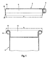
- FIG. 1 to 3 show the method steps of the method according to the invention in a schematic representation.
- Fig. 1 shows the first and second Process step.
- the clamping ring 2 which is shown in section in Fig. 1, comprises an annular Element 4 and a latch 6.
- the container 8 to be closed is shown in the lower region of FIG. 1.
- the container 8 has an edge 10 pointing radially outward on the opening side on, which in the present case is formed by a border.
- a cup-shaped cover 12 used, which has a lid edge 14.
- the lid edge 14 is also as Edge trim formed and rests on the edge 10 of the container 8.
- the annular element 4 of the clamping ring 2 has a first in cross section Leg 16, which is able to overlap the lid edge 14. To the The first leg 16 is followed by a second leg 18, which the edge 10 of the Containers 8 and the lid rim 14 from the outside when the clamping ring 2nd is arranged on the container 8. The second leg 18 closes again a third leg 20 which extends over the edge 10 of the container 8 protrudes below when the clamping ring 2 is placed on the container 8.
- the illustrated embodiment of the clamping ring 2 is the third leg 20 slightly angled relative to the second leg 18 and radially inward inclined, but it is also possible to use the second and third legs 18, 20 to be aligned one after the other.
- the slight slope of the third leg 20 has the advantage that the kink between the second and third Leg 18.20 can act as a predetermined bending point in the further process.
- the third leg 20 Despite the inclination of the third leg 20, it must be ensured that the smallest circle enclosed by the third leg 20 has a diameter a which is larger than the outer diameter b of the edge 10 of the container 8 and the lid edge 14, so that the third shown in Fig. 2 Process step can be carried out.
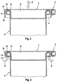
- the in the second process step tensioned ring 2 on the lid 12 in Attached in the direction of arrow A.
- the Tension ring 2 can also be placed on the separate cover 12 first then cover 12 together with clamping ring 2 onto container 8 sit up.
- the clamping ring 2 shows in particular that the first leg 16 the Cover rim 14 overlaps after the clamping ring 2 has been placed on it, during the second leg 18 the lid edge 14 and the edge 10 of the container 8 encloses and the third leg 20 down over the edge 10 of the container 8 stands out. With the third process step, the clamping ring 2 is thus in its brought final position on the container 8.
- the third leg 20 deformed such that it engages under the edge 10 of the container 10.
- the third leg 20 in Bent in the direction of arrows B, with the kink between the second leg 18 and the radially inwardly inclined third leg 20 as a predetermined bending point acts. With the help of this predetermined bending point, the final shape of the Clamping ring 2 can be largely determined beforehand.
- the third leg is deformed by means of rotating rollers, as will be the case later 4 and 5, wherein the rollers during circulating under the rim of the container can be pivoted like this is also indicated by the arrows B. Since the latch 6 is wider than the second leg 18 and thus wider than that after deforming finished clamping ring 2 is formed, part of the chip lock 6 protrudes downward over the second leg 18. By the invention Swiveling the role ensures that the role against the third Press leg 20 and deform it without touching it between the roll and the downward protruding end of the Tension lock 6 comes.
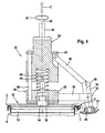
- Fig. 4 shows the device according to the invention in a sectional view.
- the device according to the invention comprises a tensioning device 22 and three rollers 24, of which only one is shown for reasons of clarity.
- the Clamping device 22 is arranged on a central axis 26, which at the same time the Central axis of the container 8 represents the bottom in Fig. 4 together with the Cover 12 is shown.
- the tensioning device 22 is along the central axis 26 movable, as shown by arrow C, and points in essentially a frame 28, a carriage 30 and a plate 32.
- the plate 32 is on the lid 12 and the clamping ring 2 of the container 8 attachable and is rotatable via a shaft 34 in the frame 28 of the Clamping device 22 mounted, this in the present embodiment via a roller bearing 36.
- the frame comprises a lower part 38 in which the shaft 34 is supported, a plurality of webs 40, only one of which is shown and which, starting from the lower part 38, is parallel to the central axis 26 extend upward, and an annular plate 42 which completes the forms upper ends of the webs 40.
- the carriage 30 of the jig 22 is Slidably mounted on the webs 40 and thus between the lower part 38 and the annular plate 42 of the frame 28 slidably arranged.
- a compression spring 44 Between the upward side of the lower part 38 and the lower part 38 facing side of the carriage 30 is also a compression spring 44, so that the carriage 30 by the compression spring 44 against the annular plate 42nd is depressed when the tensioning device 22 is relaxed.
- a stop element 46 On the carriage 30 facing side of the lower part 38 is also a stop element 46 arranged, which is adjustable in height along the central axis 26 and as Stop for the carriage 30 is used.
- a portion of the carriage 30 extends through the annular plate 42 and is firmly connected to a drive shaft 48, wherein the drive shaft 48 can be rotated about the central axis 26 like this is indicated by the arrow D.
- struts 50 pointing radially outwards attached, of which in turn only one is shown and which on their Each end have a fork 52.
- a first lever 54 in the fork 52 pivoted the end pointing in the direction of the plate 32 receives the roller 24 which is rotatable on the first by means of a roller bearing 56 Lever 54 is arranged.
- the first lever 54 thus extends in the direction of the Roller axis 58 and can be pivoted in a plane in which the Central axis 26 lies.
- a second lever 60 is articulated, the other end of which is connected to the slide 30 the tensioning device 22 is articulated.
- the shaft 48 is in one direction of arrow D rotates. This rotation is transmitted via the carriage 30 and the Web 40 on the frame 28.
- the plate 32 also takes place despite the roller bearing the rotational movement after, but this is only due to the frictional forces within the Roller bearing 36 can be attributed and is meaningless for the further process.
- the roller axes 58 also rotate by transmitting the rotation about the struts 50 and the second lever 60 about the central axis, so that the Rollers 24 describe a circular path.
- the tensioning device 22 is opened in the direction of arrow C. the container 8 lowered, causing the plate 32 on the clamping ring 2 and Cover 12 comes to rest, as shown in Fig. 4.
- the plate 32 is designed such that the container 8 is below the clamping device 22nd centered. As soon as the plate 32 is placed on the container 8, its rotation prevented so that only the carriage 30 and the frame 28 of the Continue to rotate the jig. A transfer of the rotation to the Container 8 is excluded due to the roller bearing 36.
- Fig. 5 illustrates that by pivoting the roller axis 58 of the Tension lock 6 of the tension ring 2 can be reached without contact, so that the device securely closes the container 8 without collision Rollers 24 with the latch 6 allows.
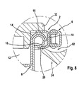
- FIG. 6 to 8 are intended to illustrate that the safe closing of the container 8th by means of the clamping ring 2 with a latch 6 also on the special design of the cross section of the rollers 24 is based.
- the figures show the individual phases of the deformation process of the third leg 20 of the tension ring 2.
- the roller 24 is already against the third leg 20 pivoted. 7
- the roller 24 is still further against the third leg 20 pivots and engages under the edge 10 of the container, so that the third Leg 20 is bent radially inwards.
- 8 shows section II of FIG Fig. 5, d. H.
- the third leg 20 is bent to the bottom of the edge 10, and the clamping ring 2 has thus assumed its final shape.
- the in the 6 to 8 shown roller 24 has a cross section that is nose-like is trained.
- the end face of the roller 24 facing away from the clamping ring 2 falls radially outwards, so it is essentially conical.
- the one Clamping ring 2 facing end of the roller 24 has a circumferential recess 62 on that of the contactless recording of the downward projecting end the latch 6 serves. This can be seen in particular in FIG. 8. Together with the pivotability of the roller axis 58, this enables special design of the roller 24 thus a collision-free operation of the device according to the invention.
Landscapes
- Engineering & Computer Science (AREA)
- Mechanical Engineering (AREA)
- Closing Of Containers (AREA)
- Sealing Of Jars (AREA)
- Closures For Containers (AREA)
- Supplying Of Containers To The Packaging Station (AREA)
Applications Claiming Priority (2)
| Application Number | Priority Date | Filing Date | Title |
|---|---|---|---|
| DE10109632A DE10109632B4 (de) | 2001-03-01 | 2001-03-01 | Verfahren und Vorrichtung zum Verschließen eines Behälters |
| DE10109632 | 2001-03-01 |
Publications (3)
| Publication Number | Publication Date |
|---|---|
| EP1236645A2 EP1236645A2 (de) | 2002-09-04 |
| EP1236645A3 EP1236645A3 (de) | 2004-02-04 |
| EP1236645B1 true EP1236645B1 (de) | 2004-11-03 |
Family
ID=7675796
Family Applications (1)
| Application Number | Title | Priority Date | Filing Date |
|---|---|---|---|
| EP02004739A Expired - Lifetime EP1236645B1 (de) | 2001-03-01 | 2002-03-01 | Verfahren und Vorrichtung zum Verschliessen eines Behälters |
Country Status (6)
| Country | Link |
|---|---|
| EP (1) | EP1236645B1 (pt) |
| AT (1) | ATE281350T1 (pt) |
| DE (2) | DE10109632B4 (pt) |
| DK (1) | DK1236645T3 (pt) |
| ES (1) | ES2227337T3 (pt) |
| PT (1) | PT1236645E (pt) |
Families Citing this family (2)
| Publication number | Priority date | Publication date | Assignee | Title |
|---|---|---|---|---|
| DE102008053299A1 (de) | 2008-10-27 | 2010-04-29 | Muhr & Söhne GmbH + Co. KG | Verschließbarer Behälter für chemische Füllgüter |
| CH710684A1 (de) | 2015-01-30 | 2016-08-15 | Stebler Blech Ag | Vorrichtung zum Verschliessen von Metallbehältern mit einem Einsteckdeckel. |
Family Cites Families (9)
| Publication number | Priority date | Publication date | Assignee | Title |
|---|---|---|---|---|
| GB705759A (en) * | 1951-10-06 | 1954-03-17 | Reads Ltd | Improvements relating to closures for sheet metal drums, kegs and like containers |
| GB750790A (en) * | 1954-12-23 | 1956-06-20 | John Feaver Ltd | Improvements relating to machines for closing and sealing sheet metal containers |
| US3076300A (en) * | 1960-11-07 | 1963-02-05 | Grotnes Machine Works Inc | Capping head for tamper-proof cap |
| DE1933670C3 (de) * | 1969-07-02 | 1974-01-24 | Maschinenfabrik Rissen Gmbh, 2000 Hamburg | Vorrichtung zum Verbinden des Randes eines Verpackungsbehälters mit dem benachbarten Rand eines Deckels |
| US3674605A (en) * | 1969-11-28 | 1972-07-04 | Aluminium Francais | Process for the assembly of sheets and apparatus for same |
| CH614416A5 (pt) * | 1977-05-23 | 1979-11-30 | Mueller Ernst Ag | |
| DE9012138U1 (de) * | 1990-07-24 | 1990-10-18 | Stebler & Co AG, Nunningen | Spannring zum Festhalten eines Deckels in einem Eimer und Vorrichtung zum Schliessen dieses Spannringes |
| DE10005299A1 (de) * | 1999-02-07 | 2001-01-25 | Impress Gmbh & Co Ohg | Verschließen von eimerförmigen Behältern |
| DE29909398U1 (de) * | 1999-05-31 | 1999-11-25 | Horn, Klaus, 21409 Embsen | Schließvorrichtung zum Schließen eines Behälters mit einem Deckel durch einen radial gespaltenen Spannring |
-
2001
- 2001-03-01 DE DE10109632A patent/DE10109632B4/de not_active Expired - Fee Related
-
2002
- 2002-03-01 PT PT02004739T patent/PT1236645E/pt unknown
- 2002-03-01 DE DE50201423T patent/DE50201423D1/de not_active Expired - Lifetime
- 2002-03-01 ES ES02004739T patent/ES2227337T3/es not_active Expired - Lifetime
- 2002-03-01 AT AT02004739T patent/ATE281350T1/de active
- 2002-03-01 EP EP02004739A patent/EP1236645B1/de not_active Expired - Lifetime
- 2002-03-01 DK DK02004739T patent/DK1236645T3/da active
Also Published As
| Publication number | Publication date |
|---|---|
| EP1236645A3 (de) | 2004-02-04 |
| DE10109632B4 (de) | 2005-07-28 |
| EP1236645A2 (de) | 2002-09-04 |
| ES2227337T3 (es) | 2005-04-01 |
| DE10109632A1 (de) | 2002-09-19 |
| ATE281350T1 (de) | 2004-11-15 |
| DE50201423D1 (de) | 2004-12-09 |
| PT1236645E (pt) | 2005-01-31 |
| DK1236645T3 (da) | 2005-01-24 |
Similar Documents
| Publication | Publication Date | Title |
|---|---|---|
| EP1853408B1 (de) | Vorrichtung und verfahren zum herstellen einer schraubverbindung zwischen einem ersten bauteil und mindestens einem weiteren bauteil | |
| DE4234115C2 (de) | Typenwechselvorrichtung bei einer Dosenverschließmaschine | |
| DE69828209T2 (de) | Flanschreformierung | |
| WO1994012296A1 (de) | Presswerkzeug | |
| EP2025471A2 (de) | Niederzugspanner | |
| WO1994012297A1 (de) | Presswerkzeug | |
| DE1928490A1 (de) | Schlossmutteranordnung | |
| DE2114004A1 (de) | Klemmvorrichtung | |
| DE69303122T2 (de) | Verbesserungen an Vorrichtungen zum Formen von Flanschen an Dosen | |
| DE19503682C1 (de) | Schnellwechselvorrichtung für Walzscheiben | |
| DE2510543B2 (de) | Vorrichtung zum gleichzeitigen Aushalsen und Bördeln von Metalldosen | |
| DE69514982T2 (de) | Verfahren und Vorrichtung zum Verlängern und zum Entspannen eines Zapfens oder dergleichen | |
| EP1117497B1 (de) | Fügevorrichtung, durchsetzfügeverfahren und durchsetzfügeverbindung | |
| EP1236645B1 (de) | Verfahren und Vorrichtung zum Verschliessen eines Behälters | |
| WO2016062515A1 (de) | Presswerkzeug | |
| DE2132642A1 (de) | Einwickelwalzenanordnung fuer eine Muenzverpackungsmaschine | |
| EP1167222B1 (de) | Behälter mit Randbordierung und Verfahren zur Herstellung der Randbordierung | |
| EP0882650A1 (de) | Verfahren zum Verbinden eines Unterteils eines Verpackungsbehälters mit einem Verschlusselement | |
| DE2611175C3 (de) | Schlauchbefestigungsvorrichtung | |
| DE102017128474B3 (de) | Rohrschneidemaschine mit Schneiddorn | |
| DE3210448A1 (de) | Schnellspannmutter | |
| EP2998258A1 (de) | Folienaufwickelvorrichtung für eine Verpackungsmaschine | |
| DE812488C (de) | Kegelrollenlager und Verfahren zu seinem Zusammenbau | |
| DE2553556B2 (de) | Verstellvorrichtung an fotografischen VergröBerungs- oder Reprogeräten | |
| EP3828015B1 (de) | Vorrichtung zum spannen einer felge eines fahrzeugrades |
Legal Events
| Date | Code | Title | Description |
|---|---|---|---|
| PUAI | Public reference made under article 153(3) epc to a published international application that has entered the european phase |
Free format text: ORIGINAL CODE: 0009012 |
|
| AK | Designated contracting states |
Kind code of ref document: A2 Designated state(s): AT BE CH CY DE DK ES FI FR GB GR IE IT LI LU MC NL PT SE TR |
|
| AX | Request for extension of the european patent |
Free format text: AL;LT;LV;MK;RO;SI |
|
| PUAL | Search report despatched |
Free format text: ORIGINAL CODE: 0009013 |
|
| AK | Designated contracting states |
Kind code of ref document: A3 Designated state(s): AT BE CH CY DE DK ES FI FR GB GR IE IT LI LU MC NL PT SE TR |
|
| AX | Request for extension of the european patent |
Extension state: AL LT LV MK RO SI |
|
| 17P | Request for examination filed |
Effective date: 20040302 |
|
| GRAP | Despatch of communication of intention to grant a patent |
Free format text: ORIGINAL CODE: EPIDOSNIGR1 |
|
| GRAS | Grant fee paid |
Free format text: ORIGINAL CODE: EPIDOSNIGR3 |
|
| GRAA | (expected) grant |
Free format text: ORIGINAL CODE: 0009210 |
|
| AKX | Designation fees paid |
Designated state(s): AT BE CH CY DE DK ES FI FR GB GR IE IT LI LU MC NL PT SE TR |
|
| AK | Designated contracting states |
Kind code of ref document: B1 Designated state(s): AT BE CH CY DE DK ES FI FR GB GR IE IT LI LU MC NL PT SE TR |
|
| PG25 | Lapsed in a contracting state [announced via postgrant information from national office to epo] |
Ref country code: FI Free format text: LAPSE BECAUSE OF FAILURE TO SUBMIT A TRANSLATION OF THE DESCRIPTION OR TO PAY THE FEE WITHIN THE PRESCRIBED TIME-LIMIT Effective date: 20041103 Ref country code: IE Free format text: LAPSE BECAUSE OF FAILURE TO SUBMIT A TRANSLATION OF THE DESCRIPTION OR TO PAY THE FEE WITHIN THE PRESCRIBED TIME-LIMIT Effective date: 20041103 |
|
| REG | Reference to a national code |
Ref country code: GB Ref legal event code: FG4D Free format text: NOT ENGLISH |
|
| REG | Reference to a national code |
Ref country code: CH Ref legal event code: EP |
|
| REF | Corresponds to: |
Ref document number: 50201423 Country of ref document: DE Date of ref document: 20041209 Kind code of ref document: P |
|
| REG | Reference to a national code |
Ref country code: IE Ref legal event code: FG4D Free format text: GERMAN |
|
| REG | Reference to a national code |
Ref country code: SE Ref legal event code: TRGR |
|
| REG | Reference to a national code |
Ref country code: DK Ref legal event code: T3 |
|
| REG | Reference to a national code |
Ref country code: PT Ref legal event code: SC4A Effective date: 20041117 |
|
| GBT | Gb: translation of ep patent filed (gb section 77(6)(a)/1977) |
Effective date: 20050106 |
|
| PG25 | Lapsed in a contracting state [announced via postgrant information from national office to epo] |
Ref country code: GR Free format text: LAPSE BECAUSE OF FAILURE TO SUBMIT A TRANSLATION OF THE DESCRIPTION OR TO PAY THE FEE WITHIN THE PRESCRIBED TIME-LIMIT Effective date: 20050203 |
|
| PG25 | Lapsed in a contracting state [announced via postgrant information from national office to epo] |
Ref country code: CY Free format text: LAPSE BECAUSE OF FAILURE TO SUBMIT A TRANSLATION OF THE DESCRIPTION OR TO PAY THE FEE WITHIN THE PRESCRIBED TIME-LIMIT Effective date: 20050301 Ref country code: LU Free format text: LAPSE BECAUSE OF NON-PAYMENT OF DUE FEES Effective date: 20050301 |
|
| PG25 | Lapsed in a contracting state [announced via postgrant information from national office to epo] |
Ref country code: MC Free format text: LAPSE BECAUSE OF NON-PAYMENT OF DUE FEES Effective date: 20050331 |
|
| REG | Reference to a national code |
Ref country code: ES Ref legal event code: FG2A Ref document number: 2227337 Country of ref document: ES Kind code of ref document: T3 |
|
| REG | Reference to a national code |
Ref country code: IE Ref legal event code: FD4D |
|
| PLBE | No opposition filed within time limit |
Free format text: ORIGINAL CODE: 0009261 |
|
| STAA | Information on the status of an ep patent application or granted ep patent |
Free format text: STATUS: NO OPPOSITION FILED WITHIN TIME LIMIT |
|
| ET | Fr: translation filed | ||
| 26N | No opposition filed |
Effective date: 20050804 |
|
| REG | Reference to a national code |
Ref country code: DE Ref legal event code: R082 Ref document number: 50201423 Country of ref document: DE Representative=s name: FRANK OPPERMANN, DE Ref country code: DE Ref legal event code: R082 Ref document number: 50201423 Country of ref document: DE Representative=s name: OPPERMANN, FRANK, DIPL.-ING., DE |
|
| REG | Reference to a national code |
Ref country code: FR Ref legal event code: PLFP Year of fee payment: 15 |
|
| REG | Reference to a national code |
Ref country code: FR Ref legal event code: PLFP Year of fee payment: 16 |
|
| REG | Reference to a national code |
Ref country code: FR Ref legal event code: PLFP Year of fee payment: 17 |
|
| PGFP | Annual fee paid to national office [announced via postgrant information from national office to epo] |
Ref country code: CH Payment date: 20210324 Year of fee payment: 20 Ref country code: FR Payment date: 20210322 Year of fee payment: 20 Ref country code: PT Payment date: 20210222 Year of fee payment: 20 Ref country code: NL Payment date: 20210319 Year of fee payment: 20 |
|
| PGFP | Annual fee paid to national office [announced via postgrant information from national office to epo] |
Ref country code: AT Payment date: 20210318 Year of fee payment: 20 Ref country code: DE Payment date: 20210225 Year of fee payment: 20 Ref country code: BE Payment date: 20210322 Year of fee payment: 20 Ref country code: TR Payment date: 20210301 Year of fee payment: 20 Ref country code: SE Payment date: 20210323 Year of fee payment: 20 Ref country code: GB Payment date: 20210324 Year of fee payment: 20 Ref country code: DK Payment date: 20210323 Year of fee payment: 20 |
|
| PGFP | Annual fee paid to national office [announced via postgrant information from national office to epo] |
Ref country code: IT Payment date: 20210331 Year of fee payment: 20 |
|
| PGFP | Annual fee paid to national office [announced via postgrant information from national office to epo] |
Ref country code: ES Payment date: 20210421 Year of fee payment: 20 |
|
| REG | Reference to a national code |
Ref country code: DE Ref legal event code: R071 Ref document number: 50201423 Country of ref document: DE |
|
| REG | Reference to a national code |
Ref country code: NL Ref legal event code: MK Effective date: 20220228 |
|
| REG | Reference to a national code |
Ref country code: DK Ref legal event code: EUP Expiry date: 20220301 |
|
| REG | Reference to a national code |
Ref country code: CH Ref legal event code: PL |
|
| REG | Reference to a national code |
Ref country code: GB Ref legal event code: PE20 Expiry date: 20220228 |
|
| REG | Reference to a national code |
Ref country code: BE Ref legal event code: MK Effective date: 20220301 |
|
| REG | Reference to a national code |
Ref country code: AT Ref legal event code: MK07 Ref document number: 281350 Country of ref document: AT Kind code of ref document: T Effective date: 20220301 |
|
| PG25 | Lapsed in a contracting state [announced via postgrant information from national office to epo] |
Ref country code: GB Free format text: LAPSE BECAUSE OF EXPIRATION OF PROTECTION Effective date: 20220228 |
|
| REG | Reference to a national code |
Ref country code: SE Ref legal event code: EUG |
|
| PG25 | Lapsed in a contracting state [announced via postgrant information from national office to epo] |
Ref country code: PT Free format text: LAPSE BECAUSE OF EXPIRATION OF PROTECTION Effective date: 20220310 |
|
| REG | Reference to a national code |
Ref country code: ES Ref legal event code: FD2A Effective date: 20220624 |
|
| PG25 | Lapsed in a contracting state [announced via postgrant information from national office to epo] |
Ref country code: ES Free format text: LAPSE BECAUSE OF EXPIRATION OF PROTECTION Effective date: 20220302 |