EP1236256B1 - Cable grommet - Google Patents
Cable grommet Download PDFInfo
- Publication number
- EP1236256B1 EP1236256B1 EP00992064A EP00992064A EP1236256B1 EP 1236256 B1 EP1236256 B1 EP 1236256B1 EP 00992064 A EP00992064 A EP 00992064A EP 00992064 A EP00992064 A EP 00992064A EP 1236256 B1 EP1236256 B1 EP 1236256B1
- Authority
- EP
- European Patent Office
- Prior art keywords
- strain relief
- cable
- cable bushing
- frame parts
- aperture
- Prior art date
- Legal status (The legal status is an assumption and is not a legal conclusion. Google has not performed a legal analysis and makes no representation as to the accuracy of the status listed.)
- Expired - Lifetime
Links
Images


Classifications
-
- H—ELECTRICITY
- H02—GENERATION; CONVERSION OR DISTRIBUTION OF ELECTRIC POWER
- H02G—INSTALLATION OF ELECTRIC CABLES OR LINES, OR OF COMBINED OPTICAL AND ELECTRIC CABLES OR LINES
- H02G3/00—Installations of electric cables or lines or protective tubing therefor in or on buildings, equivalent structures or vehicles
- H02G3/22—Installations of cables or lines through walls, floors or ceilings, e.g. into buildings
Definitions
- Cable bushings are known and e.g. in DE 197 21 659 described with an opening through which cables are to be routed can be easily connected.
- the strain reliefs have with the Frame parts only have a good hold when they are assembled, otherwise they can become loose detach from the frame parts. This is a major disadvantage in terms of assembly.
- WO 99 06 747 A describes a cable bushing that comprises two pieces.
- the pieces each have semicircular recesses, which in the assembled state of the form a full circle to accommodate a cylindrical strain relief.
- This cable entry has the disadvantage that when installing a cable with Strain relief the strain relief only in one of the semi-circular ones mentioned Cutouts are inserted and in this position with the cutout is not reliable connected is. If the fitter wants additional semicircular cutouts Strain relief and insert cables enclosed by these, there is a risk of that the previously inserted strain relief with cable comes out of the semicircular Semicircular recess falls out.
- DE 40 20 180 C describes a cable bushing in which for the seal annular sealing elements, and cable clamps are provided for strain relief. Such an embodiment has a large number of individual parts and is therefore expensive in production and also difficult to assemble.
- DE 36 19 183 relates to a cable bushing for a fuse and distribution box for motor vehicles. This is not about a cable entry that starts with Strain reliefs and cables are assembled and then assembled. Rather is there a fixed receiving part is already firmly mounted on a motor vehicle body. The receiving part has cutouts open at the top. In these recesses strain reliefs are inserted from above with cables enclosed by these, and then closed with a lid. So there’s no problem that the fitter still has to handle the cable entry when assembling and thereby brings into positions in which inserted strain reliefs from the The opening can fall out.
- the invention is therefore about specifying a cable bushing that can be easily assembled and assembled and a variety of cables can record.
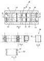
- a cable bushing 10 which consists of a base body 12 with two frame parts 14 and 16.
- the frame parts 14 and 16 can be firmly connected to each other (operating state) or loosely arranged to each other (Loose condition).
- the base body has a plurality of openings or shapes 20 to 34.
- strain reliefs 40 to 56 are arranged in these openings 20 to 34 (cf. 5), through which the cables or lines (not shown) with the base body 12 can be firmly and tightly connected. In the operating state, all components are Cable entry 10 firmly connected.
- the frame parts are loose 14, 16 captively connected to the strain reliefs 40 to 56.
- the strain relief 40 to 56 are arranged within the base body 12 with a high packing density.
- the Base body 12 is designed such that a between two openings Separating body 60 to 70 is arranged.
- the respective openings 20 to 34 are complete each formed in one piece 14 and 16.
- the drawings show that the Frame parts 14 and 16 have projections 80, 82 or recesses 84 which with the Outer wall 90, 92 of the strain relief 42, 48 can be non-positively connected.
- the Frame parts 14 and 16 have a comb-like profile and the strain reliefs 40 to 56 have an essentially cuboid or cube-shaped envelope.
- the frame parts of the cable entry could also be designed such that one piece is comb-shaped, while the other piece is in the form of a Has cover strip.
- the frame parts each have a projection 104 which fits into a Recess 106 engages the opposite frame part, so that a defined Position of both frame parts to each other is guaranteed.
- a firm connection between the frame parts 14 and 16 is made by screws which in the Openings 100 can be inserted.
- the assembly can be carried out as follows:
- the cables or lines are provided with hollow-body strain reliefs usually made of rubber or elastic plastic and slit lengthways, so that they can be clipped to the side of the cable.
- the strain relief are then inserted into the openings of the frame parts, where they are stationary and are captively arranged.
- Frame parts assembled in this way are then connected with each other.
- This modular form has the advantage that between the Frame parts a variety of cables / lines with optimal use of the Available space can be arranged.
- the intermediate piece 300 is serpentine.
- the openings 20, 30 are with Moldings 302, 304 covered. Recorded strain reliefs are in the openings 20, 30 so tensioned that the strain reliefs are held (positive and non-positive). It is one of the simplest embodiments of the invention.
- 13 is the Cable entry similar to that in Fig. 9.
- the frame parts 14 ', 16' have none Separating body. Separator 302, 304 has only the intermediate piece 300. The ends of the Separating bodies 302, 304 touch the inner sides of the frame parts 14 ', 16'.
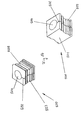
- the strain relief 500 is a cube or cuboid with an opening 504.
- the diameter of the opening 504 is open adjusted the diameter of the cable If the cable entry with Strain relief, then the cables are held by the cable entry.
- the strain relief 500 has a flat and flat top side 501 and side surfaces 503, 505 with grooves.
- the strain relief 500 is in the frame parts 14, 16 in the direction of Arrow inserted.
- the side surfaces 503, 505 are with the separating bodies 60 to 70 connected, firmly, so that there is no displacement of the strain relief 500 in Cable direction can come.
- the side surfaces 503, 505 are with the separating bodies 60 up to 70 positively and non-positively connected.
- the flat top side 501 is in the Height of the free ends of the separators 60 to 70, but it can also be minimal protrude from the frame parts 14, 16. When connecting two frame parts 14, 16 each with a row of strain reliefs then push these rows over the flat deck sides 501 together. This creates a tight connection between the Series.
- the cover side 501 could also be designed differently. It is important that the Assembling a tight connection is made.
Landscapes
- Engineering & Computer Science (AREA)
- Architecture (AREA)
- Civil Engineering (AREA)
- Structural Engineering (AREA)
- Installation Of Indoor Wiring (AREA)
- Insulating Bodies (AREA)
- Suspension Of Electric Lines Or Cables (AREA)
- Communication Cables (AREA)
- Details Of Connecting Devices For Male And Female Coupling (AREA)
Abstract
Description
Es sind Kabeldurchführungen bekannt und z.B. in der DE 197 21 659 beschrieben, die mit einer Öffnung, durch die Kabel geführt werden sollen, gut verbunden werden können. Das Konfektionieren (=Bestücken) solcher Kabeldurchführungen ist aber schwierig, weil das Einbringen der Zugentlastungen mit Kabeln oder Leitungen zwischen die Rahmenteile - auch "Stücke" genannt - umständlich ist. Die Zugentlastungen haben mit den Rahmenteilen nur dann einen guten Halt, wenn sie montiert sind, sonst können sie sich von den Rahmenteilen lösen. Das ist ein großer Montagenachteil.Cable bushings are known and e.g. in DE 197 21 659 described with an opening through which cables are to be routed can be easily connected. The Assembling (= equipping) such cable entries is difficult because that Introduce the strain relief with cables or wires between the Frame parts - also called "pieces" - is cumbersome. The strain reliefs have with the Frame parts only have a good hold when they are assembled, otherwise they can become loose detach from the frame parts. This is a major disadvantage in terms of assembly.
WO 99 06 747 A beschreibt eine Kabeldurchführung, die zwei Stücke umfasst. Die Stücke haben jeweils halbkreisförmige Aussparungen, die in zusammengefügtem Zustand der beiden Stücke einen Vollkreis zur Aufnahme einer zylindrischen Zugentlastung bilden. Diese Kabeldurchführung hat den Nachteil, dass bei der Montage eines Kabels mit Zugentlastung die Zugentlastung nur in eine der genannten halbkreisförmigen Aussparungen eingelegt wird und in dieser Position mit der Aussparung nicht zuverlässig verbunden ist. Will der Monteur weitere halbkreisförmige Aussparungen mit Zugentlastungen und von diesen umschlossenen Kabeln einlegen, so besteht die Gefahr, dass die zuvor eingelegte Zugentlastung mit Kabel wieder aus der halbkreisförmigen Halbkreisaussparung herausfällt.WO 99 06 747 A describes a cable bushing that comprises two pieces. The pieces each have semicircular recesses, which in the assembled state of the form a full circle to accommodate a cylindrical strain relief. This cable entry has the disadvantage that when installing a cable with Strain relief the strain relief only in one of the semi-circular ones mentioned Cutouts are inserted and in this position with the cutout is not reliable connected is. If the fitter wants additional semicircular cutouts Strain relief and insert cables enclosed by these, there is a risk of that the previously inserted strain relief with cable comes out of the semicircular Semicircular recess falls out.
DE 40 20 180 C beschreibt eine Kabeldurchführung, bei welcher für die Abdichtung
ringförmige Dichtelemente, und für die Zugentlastung Kabelschellen vorgesehen sind.
Eine solche Ausführungsform weist eine Vielzahl von Einzelteilen auf und ist daher teuer
in der Herstellung und außerdem schwierig zu montieren.
DE 36 19 183 betrifft eine Kabeldurchführung für einen Sicherungs- und Verteilerkasten für Kraftfahrzeuge. Dabei geht es nicht um eine Kabeldurchführung, die zunächst mit Zugentlastungen und Kabeln konfektioniert, und anschließend montiert wird. Vielmehr ist dort ein ortsfestes Aufnahmeteil bereits an einer Kraftfahrzeugkarosserie fest montiert. Das Aufnahmeteil weist nach oben offene Aussparungen auf. In diese Aussparungen werden Zugentlastungen mit von diesen umschlossenen Kabeln von oben her eingelegt, und sodann mit einem Deckel verschlossen. Es tritt hierbei somit nicht das Problem auf, dass der Monteur die Kabeldurchführung beim Konfektionieren noch handhaben muss und dabei in Positionen bringt, bei denen eingelegte Zugentlastungen aus der Aufnahmeöffnung herausfallen können. Das Problem, das bei der Kabeldurchführung gemäß WO 99 06 747 A auftritt, so wie oben geschildert, liegt somit hier nicht vor, da das Aufnahmeteil ortsfest ist, die Zugentlastungen von oben her in die Aussparungen eingelegt werden und daher nicht nach unten herausfallen können, und da auch nach dem Einlegen der Zugentlastungen in die Aussparungen ein Hantieren mit dem Aufnahmeteil nicht mehr notwendig ist.DE 36 19 183 relates to a cable bushing for a fuse and distribution box for motor vehicles. This is not about a cable entry that starts with Strain reliefs and cables are assembled and then assembled. Rather is there a fixed receiving part is already firmly mounted on a motor vehicle body. The receiving part has cutouts open at the top. In these recesses strain reliefs are inserted from above with cables enclosed by these, and then closed with a lid. So there’s no problem that the fitter still has to handle the cable entry when assembling and thereby brings into positions in which inserted strain reliefs from the The opening can fall out. The problem with cable entry occurs according to WO 99 06 747 A, as described above, is therefore not present here because the Receiving part is stationary, the strain relief from above into the recesses be inserted and therefore cannot fall out downwards, and also after handling the strain reliefs in the recesses Recording part is no longer necessary.
Bei der Erfindung geht es somit darum, eine Kabeldurchführung anzugeben, die problemlos konfektioniert und montiert werden kann und eine Vielzahl von Kabeln aufnehmen kann.The invention is therefore about specifying a cable bushing that can be easily assembled and assembled and a variety of cables can record.
Diese Aufgabe wird durch die Merkmale der unabhängigen Ansprüche 1 und 11 gelöst.
Die Vorteile der Erfindung sind folgende:
Weitere Vorteile der Erfindung sind in den Unteransprüchen angegeben.Further advantages of the invention are specified in the subclaims.
Ein Ausführungsbeispiel der Erfindung ist in der Zeichnung schematisch dargestellt und wird im Folgenden erläutert. An embodiment of the invention is shown schematically in the drawing and is explained below.
Es zeigen
- Fig. 1
- eine Kabeldurchführung in Perspektive
- Fig. 2
- eine vertikale Draufsicht der Kabeldurchführung nach Fig. 1,
- Fig. 3
- die Kabeldurchführung nach Fig. 1 in Vorderansicht,
- Fig. 4
- eine Variante der Kabeldurchführung nach Fig. 1,
- Fig. 5
- eine Kabeldurchführung in Stirnansicht,
- Fig. 6
- einen Teilschnitt entlang der Linie VI-VI nach Fig. 5,
- Fig. 7
- eine Zugentlastung,
- Fig. 8
- eine weitere Zugentlastung,
- Fig. 9
- eine weitere Kabeldurchführung mit einem Zwischenstück in Explosionsdarstellung,
- Fig. 10
- die Kabeldurchführung nach Fig. 9 in Draufsicht,
- Fig. 11
- die Kabeldurchführung nach Fig. 9 in zusammengebautem Zustand,
- Fig. 12
- eine weitere Ausführung der Kabeldurchführung,
- Fig. 13
- eine weitere Ausführung der Kabeldurchführung, und
- Fig. 14
- eine Zugentlastung in zwei perspektivischen Ansichten
- Fig. 1
- a cable entry in perspective
- Fig. 2
- 2 shows a vertical top view of the cable bushing according to FIG. 1,
- Fig. 3
- 1 in front view,
- Fig. 4
- 1 shows a variant of the cable bushing according to FIG. 1,
- Fig. 5
- a cable entry in front view,
- Fig. 6
- 5 shows a partial section along the line VI-VI according to FIG. 5,
- Fig. 7
- a strain relief,
- Fig. 8
- another strain relief,
- Fig. 9
- another cable bushing with an intermediate piece in an exploded view,
- Fig. 10
- 9 in top view,
- Fig. 11
- 9 in the assembled state,
- Fig. 12
- another version of the cable entry,
- Fig. 13
- another version of the cable entry, and
- Fig. 14
- a strain relief in two perspective views
In der Zeichnung ist eine Kabeldurchführung 10 gezeigt, die aus einem Grundkörper 12
mit zwei Rahmenteilen 14 und 16 besteht. Die Rahmenteile 14 und 16 können
miteinander fest verbunden sein (Betriebszustand) oder lose zueinander angeordnet sein
(Losezustand). Der Grundkörper hat mehrere Öffnungen bzw. Ausformungen 20 bis 34. In
diesen Öffnungen 20 bis 34 sind einstückige Zugentlastungen 40 bis 56 angeordnet (vgl.
Fig. 5), durch welche die Kabel oder Leitungen (nicht dargestellt) mit dem Grundkörper 12
fest und dicht verbunden werden können. Im Betriebszustand sind alle Bauteile der
Kabeldurchführung 10 fest miteinander verbunden. Im Losezustand sind die Rahmenteile
14, 16 mit den Zugentlastungen 40 bis 56 unverlierbar verbindbar. Die Zugentlastungen
40 bis 56 sind innerhalb des Grundkörpers 12 mit hoher Packungsdichte angeordnet. Der
Grundkörper 12 ist dabei so ausgebildet, daß zwischen jeweils zwei Öffnungen ein
Trennkörper 60 bis 70 angeordnet ist. Die jeweiligen Öffnungen 20 bis 34 sind vollständig
in jeweils einem Stück 14 und 16 ausgebildet. Die Zeichnungen zeigen, daß die
Rahmenteile 14 und 16 Vorsprünge 80, 82 oder Ausnehmungen 84 aufweisen, die mit der
Außenwand 90, 92 der Zugentlastung 42, 48 kraftschlüssig verbindbar sind. Die
Rahmenteile 14 und 16 haben ein kammartiges Profil und die Zugentlastungen 40 bis 56
weisen eine im Wesentlichen quader- oder würfelförmige Umhüllung auf.In the drawing, a
Allgemein könnten die Rahmenteile der Kabeldurchführung auch so ausgebildet sein, daß ein Stück kammartig ausgebildet ist, während das andere Stück die Form einer Abdeckleiste aufweist.In general, the frame parts of the cable entry could also be designed such that one piece is comb-shaped, while the other piece is in the form of a Has cover strip.
Die Rahmenteile besitzen jeweils einen Vorsprung 104, der in eine passende
Ausnehmung 106 des gegenüberliegenden Rahmenteiles eingreift, so daß eine definierte
Position beider Rahmenteile zueinander gewährleistet ist. Eine feste Verbindung
zwischen den Rahmenteilen 14 und 16 wird durch Schrauben hergestellt, die in die
Öffnungen 100 gesteckt werden können.The frame parts each have a
Die Kabel oder Leitungen werden mit hohlkörperartigen Zugentlastungen versehen, die gewöhnlich aus Gummi oder elastischem Kunststoff bestehen und längs geschlitzt sind, so daß sie auf die Leitung seitlich aufgeklipst werden können. Die Zugentlastungen werden sodann in die Öffnungen der Rahmenteile gesteckt, wo sie ortsfest und unverlierbar angeordnet sind. So bestückte Rahmenteile werden anschließend miteinander verbunden. Diese Baukastenform hat den Vorteil, daß zwischen den Rahmenteilen eine Vielzahl von Kabeln/Leitungen unter optimaler Nutzung des zur Verfügung stehenden Raumes angeordnet werden kann. The cables or lines are provided with hollow-body strain reliefs usually made of rubber or elastic plastic and slit lengthways, so that they can be clipped to the side of the cable. The strain relief are then inserted into the openings of the frame parts, where they are stationary and are captively arranged. Frame parts assembled in this way are then connected with each other. This modular form has the advantage that between the Frame parts a variety of cables / lines with optimal use of the Available space can be arranged.
In den Fig. 9, 10 und 11 ist eine Kabeldurchführung gezeichnet. Wichtig ist hier, daß
zwischen den beiden Rahmenteilen 14, 16 ein Zwischenstück 200 angeordnet ist. Es ist
so gemacht, daß seine Trennkörper 202, 204 und die Trennkörper 60, 64 der
Rahmenteile 14, 16 fluchten, was am besten in Fig. 11 dargestellt ist. So werden zwei
Reihen von Öffnungen 20, 32 gebildet. Es besteht auch die Möglichkeit, mehrere solche
Zwischenstücke 200 zusammenzufügen, so das auch drei, vier oder mehrere Reihen von
Öffnungen gebildet werden können. In der Praxis kommt es darauf an, welchen
Durchmesser die Kabel und welche Größe die entsprechenden Zugentlastungen haben.9, 10 and 11, a cable bushing is drawn. It is important here that
an
In Fig. 12 ist das Zwischenstück 300 schlangenförmig. Die Öffnungen 20, 30 sind mit
Leisten 302, 304 abgedeckt. Aufgenommene Zugentlastungen sind in den Öffnungen 20,
30 so verspannt, daß die Zugentlastungen festgehalten werden (Form- und Kraftschluß).
Es ist eine der einfachsten Ausführungen der Erfindung. In Fig. 13 ist die
Kabeldurchführung ähnlich wie in Fig. 9. Die Rahmenteile 14', 16' haben aber keine
Trennkörper. Trennkörper 302, 304 hat nur das Zwischenstück 300. Die Enden der
Trennkörper 302, 304 berühren die Innenseiten der Rahmenteile 14', 16'.12, the
Die Fig. 14 zeigt eine Zugentlastung 500 mit einem Schlitz 502. Die Zugentlastung 500 ist
ein Würfel oder Quader mit einer Öffnung 504. Der Durchmesser der Öffnung 504 ist auf
den Durchmesser des Kabels angepaßt Wenn die Kabeldurchführung Kabel mit
Zugentlastungen trägt, dann sind die Leitungen von der Kabeldurchführung festgehalten.14 shows a
Die Zugentlastung 500 hat eine flache und ebene Deckseite 501 und Seitenflächen 503,
505 mit Nuten. Die Zugentlastung 500 wird in die Rahmenteile 14, 16 in Richtung des
Pfeils gesteckt. Die Seitenflächen 503, 505 werden mit den Trennkörpem 60 bis 70
verbunden, und zwar fest, so daß es zu keiner Verschiebung der Zugentlastung 500 in
Kabelrichtung kommen kann. Die Seitenflächen 503, 505 sind mit den Trennkörpern 60
bis 70 formschlüssig und kraftschlüssig verbunden. Die ebene Deckseite 501 ist in der
Höhe der freien Enden der Trennkörpem 60 bis 70, sie kann aber auch minimal
herausragen aus den Rahmenteilen 14, 16. Beim Verbinden von zwei Rahmenteilen 14,
16 mit jeweils einer Reihe von Zugentlastungen stoßen dann diese Reihen über die
ebenen Deckseiten 501 zusammen. So entsteht eine dichte Verbindung zwischen den
Reihen. Die Deckseite 501 könnte auch anders ausgebildet sein. Wichtig ist, daß beim
Zusammenbau eine dichte Verbindung hergestellt wird. The
Zu den wichtigsten Merkmalen der Erfindung zählen folgende:
Claims (11)
- Cable bushing (10) for preassembly with strain relief devices (40 to 56) and with cables and for subsequent fitting to a switch cabinet or another object comprising the following features:1.1 at least two frame parts (14, 16, 14', 16', 200, 300, 300', 302, 304) are loosely associated with one another in the loose state, and in the operating state are rigidly connected to one another;1.2 each frame part (14, 16, 14', 16', 200, 300, 300', 302, 304) has at least one receiving aperture (20 to 34) for receiving a strain relief device (40 to 56);1.3 each strain relief device (40 to 56) is elastically deformable;1.4 each strain relief device (40 to 56) has a through-aperture for surrounding a cable and also a slot (502) for inserting the cable into the through-aperture;1.5 in the operating state the cables are inserted in a rigid and tight manner in the strain relief devices (40 to 56), and the strain relief devices (40 to 56) are fixed in a rigid and tight manner in the receiving apertures (20 to 34) of the frame parts (14, 16, 14', 16', 200, 300, 300', 302, 304); characterised by the following features:1.6 in the loose state, each strain relief device (40 to 56) can be inserted in a drawer-like manner into a corresponding receiving aperture (20 to 34) of the frame parts (14, 16, 14', 16', 200, 300, 300', 302, 304), and in the inserted state is held non-positively and captively.
- Cable bushing (10) according to claim 1, characterised in that each strain relief device in the loose state is also held non-positively in its receiving aperture.
- Cable bushing according to claim 1 or 2, characterised in that the respective receiving apertures (20 to 34) are provided, primarily, only in one of the frame parts (14, 16).
- Cable bushing (1) according to claim 3, characterised in that the respective receiving apertures (20 to 34) are completely formed in one respective frame part (14, 16).
- Cable bushing (10) according to any one of claims 1 to 4, characterised in that at least one frame part (14, 16) has a comb-like profile.
- Cable bushing (10) according to any one of claims 1 to 5, characterised in that the individual strain relief devices (40 to 56) comprise a substantially cuboid or dice-shaped covering.
- Cable bushing (10) according to any one of claims 1 to 6, characterised in that the line of force in the operating state extends transversely to the frame parts (14, 16) and crosses the face of the slot (502).
- Cable bushing (10) according to any one of claims 1 to 7, characterised in that the strain relief devices (40 to 56) are arranged in at least one row.
- Cable bushing (10) according to any one of claims 1 to 8, characterised in that the strain relief devices (40 to 56) are arranged in two or more parallel rows, and in that the strain relief devices (40 to 56) in rows adjacent to one another are joined together in a tight pressure connection.
- Cable bushing (10) according to any one of claims 1 to 9, characterised in that a respective row of strain relief devices (40 to 56) is received by a respective frame part (14, 16).
- Cable bushing (10) for preassembly with strain relief devices (40 to 56) and with cables and for subsequent fitting to a switch cabinet or another object, comprising the following features:11.1 at least two frame parts (14, 16, 14', 16', 200, 300, 300', 302, 304) in the loose state are loosely associated with one another, and in the operating state are rigidly connected to one another;11.2 one frame part (200, 300, 300') comprises at least one receiving aperture (20, 34) for receiving a strain relief device (40 to 56), while the other frame part (14', 16', 302, 304) has the form of a cover;11.3 each strain relief device (40 to 56) is elastically deformable;11.4 each strain relief device (40 to 56) has a through-aperture for surrounding a cable and also a slot (502) for inserting the cable into the through-aperture;11.5 in the operating state, the cables are fixed rigidly and tightly in the strain relief devices (40 to 50) and the strain relief devices (40 to 56) are fixed rigidly and tightly in the relevant receiving aperture (20 to 34) of the one frame part (200, 300, 300');11.6 in the loose state each strain relief device (40 to 56) can be inserted in a drawer-like manner into a corresponding receiving aperture (20 to 34) of the one frame part (200, 300, 300'), and is held non-positively and captively in the inserted state.
Applications Claiming Priority (3)
| Application Number | Priority Date | Filing Date | Title |
|---|---|---|---|
| DE19959185A DE19959185A1 (en) | 1999-12-08 | 1999-12-08 | Cable entry |
| DE19959185 | 1999-12-08 | ||
| PCT/EP2000/011809 WO2001042046A2 (en) | 1999-12-08 | 2000-11-27 | Cable grommet |
Publications (2)
| Publication Number | Publication Date |
|---|---|
| EP1236256A2 EP1236256A2 (en) | 2002-09-04 |
| EP1236256B1 true EP1236256B1 (en) | 2003-07-09 |
Family
ID=7931860
Family Applications (1)
| Application Number | Title | Priority Date | Filing Date |
|---|---|---|---|
| EP00992064A Expired - Lifetime EP1236256B1 (en) | 1999-12-08 | 2000-11-27 | Cable grommet |
Country Status (7)
| Country | Link |
|---|---|
| US (1) | US7806374B1 (en) |
| EP (1) | EP1236256B1 (en) |
| AT (1) | ATE244946T1 (en) |
| AU (1) | AU4047701A (en) |
| DE (3) | DE19959185A1 (en) |
| ES (1) | ES2202221T3 (en) |
| WO (1) | WO2001042046A2 (en) |
Cited By (7)
| Publication number | Priority date | Publication date | Assignee | Title |
|---|---|---|---|---|
| DE102005002879A1 (en) * | 2005-01-21 | 2006-08-03 | Schmid, Gabriele | Round material`s e.g. cable, passage sealing bulkhead for e.g. vehicle, has four frames enclosing rubber modules having dimension larger than frames interior, where frames and modules possesses diagonally arranged tongue and groove system |
| DE102009006383A1 (en) | 2009-01-28 | 2010-09-16 | Festo Ag & Co. Kg | Two-piece cable-strain relief device for fixing cables in region of e.g. electrical connections, has teeth rows arranged at distance from each other, where tooth of one of rows are displaced at half teeth row distance to tooth of other row |
| EP2323236A2 (en) | 2009-11-12 | 2011-05-18 | icotek project GmbH & Co. KG | Cable holding unit |
| DE202016103494U1 (en) * | 2016-06-30 | 2017-07-06 | Conta-Clip Verbindungstechnik Gmbh | Cable wall bushing and kit |
| DE202019100887U1 (en) | 2019-02-18 | 2020-05-19 | Wiska Hoppmann Gmbh | Cable entry device for configuring a cable entry arrangement |
| DE102021201300B3 (en) | 2021-02-11 | 2022-03-24 | Icotek Project Gmbh & Co. Kg | Device for passing strands through |
| DE102020126444A1 (en) | 2020-10-08 | 2022-04-14 | Cama System Gmbh | Cable bushing with a base frame and with a plurality of cable bushing modules and method for their assembly |
Families Citing this family (58)
| Publication number | Priority date | Publication date | Assignee | Title |
|---|---|---|---|---|
| DE10225046B4 (en) * | 2001-07-25 | 2013-12-24 | Icotek Project Gmbh & Co. Kg | Device for connecting a cable feed-through strip with a wall opening |
| ES2567057T3 (en) * | 2002-06-21 | 2016-04-19 | Icotek Project Gmbh & Co. Kg | Device for installing transmission lines |
| SE523975E (en) | 2002-10-10 | 2009-02-17 | Roxtec Ab | Frame |
| DE10349996B4 (en) * | 2003-10-24 | 2013-09-05 | Icotek Project Gmbh & Co. Kg | spout |
| EP1837573B1 (en) | 2006-03-20 | 2012-09-12 | Beele Engineering B.V. | System for dynamically sealing a conduit sleeve through which a pipe or cable extends |
| SE531217C2 (en) * | 2007-05-29 | 2009-01-20 | Roxtec Ab | Cable entry |
| DE102008048863B3 (en) * | 2008-09-25 | 2009-12-31 | Siemens Aktiengesellschaft | Protective insulation element for use in electrical cabinet i.e. switchgear cabinet, has plug-in connector comprising recess for receiving another plug-in connector of another protective insulation element |
| US8464985B2 (en) * | 2008-10-14 | 2013-06-18 | Steven D. Mulch | Attachment device for elongated member |
| SE533468C2 (en) * | 2009-02-04 | 2010-10-05 | Roxtec Ab | sealing systems |
| US8596589B2 (en) * | 2009-06-09 | 2013-12-03 | Syntiro Dynamics Llc | Attachable grommets for hanging pipes |
| US20110017879A1 (en) * | 2009-07-24 | 2011-01-27 | Sarah Ann Woelke | Integrated Electrical Cable Support |
| US20110016882A1 (en) * | 2009-07-24 | 2011-01-27 | Sarah Ann Woelke | Electrical Cable Shroud |
| EP2390544B1 (en) | 2010-05-25 | 2012-08-29 | Beele Engineering B.V. | An assembly and a method for providing in an opening a sealing system |
| DE102010037463A1 (en) | 2010-09-10 | 2012-03-15 | Phoenix Contact Gmbh & Co. Kg | Frame of a cable entry system and cable grommet for this |
| DE102010037465A1 (en) * | 2010-09-10 | 2012-03-15 | Phoenix Contact Gmbh & Co. Kg | Frame for cable entry systems and frame parts therefor |
| DE102011004426A1 (en) * | 2011-02-18 | 2012-08-23 | Schneider Electric Sachsenwerk Gmbh | Electrical switchgear, in particular medium-voltage switchgear |
| DE102011054294A1 (en) * | 2011-10-07 | 2013-04-11 | Phoenix Contact Gmbh & Co. Kg | Cable gland and method for mounting a cable gland |
| GB201202883D0 (en) * | 2012-02-20 | 2012-04-04 | Airbus Operations Ltd | Clamp block assembly |
| ES2626753T3 (en) | 2012-08-30 | 2017-07-25 | Beele Engineering B.V. | Sealing system for an annular space |
| ES2871406T3 (en) | 2012-12-21 | 2021-10-28 | Icotek Project Gmbh & Co Kg | Cable carrier with a U-shaped frame and several cable glands for the passage of cables |
| US8807492B2 (en) * | 2013-01-11 | 2014-08-19 | Western Oilfields Supply Company | Pipe crib-block |
| NL2010304C2 (en) * | 2013-02-14 | 2014-08-18 | Beele Eng Bv | System for sealingly holding cables which extend through an opening. |
| EP3006629A4 (en) * | 2013-05-30 | 2017-01-11 | Volvo Construction Equipment AB | Pipe fixing device for construction machine |
| DE102014016890A1 (en) | 2014-11-18 | 2016-05-19 | Jacob Gmbh Elektrotechnische Fabrik | Cable bushing |
| DE202015102280U1 (en) * | 2015-05-05 | 2016-05-10 | Conta-Clip Verbindungstechnik Gmbh | Arrangement with a wall feedthrough for several cables and kit |
| US9800041B2 (en) | 2015-05-22 | 2017-10-24 | Ryan M. Blaine | Electrical junction box |
| US20170108147A1 (en) * | 2015-10-14 | 2017-04-20 | Daniel L. Cindrich | Means and Methods of Cable Organization |
| US10221994B2 (en) * | 2016-07-19 | 2019-03-05 | Steven Marc Baiera | Modular mounting system |
| USD807729S1 (en) * | 2016-08-31 | 2018-01-16 | National Oilwell Varco, L.P. | Flowline support device |
| CN106439232A (en) * | 2016-09-27 | 2017-02-22 | 苏州先锋物流装备科技有限公司 | Simple oil pipe mounting structure |
| DE102016223425A1 (en) * | 2016-11-25 | 2018-05-30 | Icotek Project Gmbh & Co. Kg | Cable holders with partitions and a number of grommets for passing cables |
| DE202017102147U1 (en) * | 2017-04-10 | 2017-05-05 | Igus Gmbh | Cable bushing, in particular strain relief for an energy chain |
| DE102017208477A1 (en) * | 2017-05-19 | 2018-11-22 | Icotek Project Gmbh & Co. Kg | Grommet |
| USD829535S1 (en) * | 2017-07-06 | 2018-10-02 | 308, Llc | Junction box |
| USD826033S1 (en) * | 2017-08-31 | 2018-08-21 | Nzxt Inc. | Cable managing devise for case |
| USD826700S1 (en) * | 2017-08-31 | 2018-08-28 | Nzxt Inc. | Cable managing device for case |
| USD826034S1 (en) * | 2017-08-31 | 2018-08-21 | Nzxt Inc. | Cable managing devise for case |
| USD826032S1 (en) * | 2017-08-31 | 2018-08-21 | Nzxt Inc. | Cable managing device for case |
| USD822459S1 (en) * | 2017-09-05 | 2018-07-10 | Yanegijutsukenkyujo Co., Ltd. | Wiring-piping material fixture for fixing wires or pipes of a rooftop article |
| DE102017218709A1 (en) | 2017-10-19 | 2019-04-25 | Icotek Projekt Gmbh & Co. Kg | Plug-in part for a slot in a divisible cable bushing |
| US11050231B2 (en) * | 2017-11-02 | 2021-06-29 | Panduit Corp. | Access ports for electrical enclosures |
| DE202017106818U1 (en) * | 2017-11-09 | 2018-11-14 | Conta-Clip Verbindungstechnik Gmbh | Arrangement for a cable feedthrough |
| DE102018205702A1 (en) | 2018-04-16 | 2019-10-17 | Icotek Project Gmbh & Co. Kg | Grommet |
| DE102018207019A1 (en) * | 2018-05-07 | 2019-11-07 | Icotek Project Gmbh & Co. Kg | Wall bushing |
| US11387019B2 (en) * | 2018-07-31 | 2022-07-12 | Commscope Technologies Llc | Grommets for holding cables |
| CA3122484A1 (en) * | 2018-12-18 | 2020-06-25 | Saint-Augustin Canada Electric Inc. | Clamping devices |
| IT201900000034A1 (en) * | 2019-01-03 | 2020-07-03 | Detas S P A | Cable gland assembly for passing and guiding a cable |
| DE202019100362U1 (en) * | 2019-01-23 | 2020-04-24 | Conta-Clip Verbindungstechnik Gmbh | Cable entry for the passage of cables through a separating element and arrangement |
| US10668874B1 (en) * | 2019-03-20 | 2020-06-02 | Raytheon Technologies Corporation | Clamp assembly for electrical wiring harnesses |
| DE102019205115B3 (en) * | 2019-04-10 | 2020-08-13 | Icotek Project Gmbh & Co. Kg | Device for introducing cables through an opening |
| DE102020204526A1 (en) | 2020-04-08 | 2021-10-14 | Icotek Project Gmbh & Co. Kg | Device for the implementation and strain relief of strands |
| USD989607S1 (en) * | 2020-05-08 | 2023-06-20 | Ed Fisher | Cable clip |
| IT202100006518A1 (en) | 2021-03-18 | 2022-09-18 | Detas S P A | ASSEMBLY OF CABLE GLAND FOR THE PASSAGE AND GUIDE OF A CABLE |
| US20230170682A1 (en) * | 2021-11-30 | 2023-06-01 | Corning Research & Development Corporation | Telecommunication cable strain relief assemblies |
| USD1041292S1 (en) * | 2021-12-09 | 2024-09-10 | CFW Investments LLC | Cable organizer |
| USD1034160S1 (en) * | 2022-04-28 | 2024-07-09 | Worklife Brands Llc | Cable management tray |
| USD1008003S1 (en) * | 2022-05-10 | 2023-12-19 | Asg Products, Llc | Universal cable holder |
| DE202024102861U1 (en) | 2024-05-31 | 2024-07-16 | Icotek Project Gmbh & Co. Kg | Cable grommet made of an elastic material |
Citations (1)
| Publication number | Priority date | Publication date | Assignee | Title |
|---|---|---|---|---|
| DE3619183A1 (en) * | 1986-06-06 | 1987-12-10 | Audi Ag | FUSE AND DISTRIBUTION BOX FOR MOTOR VEHICLES |
Family Cites Families (25)
| Publication number | Priority date | Publication date | Assignee | Title |
|---|---|---|---|---|
| US2417260A (en) * | 1942-08-18 | 1947-03-11 | Adel Prec Products Corp | Sectional support for conduits |
| US2354919A (en) * | 1944-04-08 | 1944-08-01 | Leroy Robert Bowles | Multiple clamping device |
| US3414220A (en) * | 1966-12-30 | 1968-12-03 | Hydro Craft Inc | Clamp means |
| US3397431A (en) * | 1967-05-12 | 1968-08-20 | Hydro Craft Inc | Tube clamp assembly |
| US3695563A (en) * | 1970-06-01 | 1972-10-03 | Theodore D Evans | Hydraulic line fitting support apparatus |
| US3742119A (en) * | 1971-11-11 | 1973-06-26 | Empire Prod Inc | Terminal housing |
| US4199070A (en) * | 1977-02-15 | 1980-04-22 | Magnussen Robert O Jr | Modular rack |
| DE4020180C1 (en) * | 1990-06-25 | 1991-07-04 | Rittal-Werk Rudolf Loh Gmbh & Co Kg, 6348 Herborn, De | Sealing bung for cable passageway in wall of switching cabinet - has retaining elements gripping behind edge of rectangular aperture for rapid fixture and release |
| US5098047A (en) * | 1990-10-18 | 1992-03-24 | Flex Rail, Inc. | Tube clamp |
| US5205520A (en) * | 1992-05-26 | 1993-04-27 | Hydro-Craft, Inc. | Retaining block for clamping system |
| DE9414666U1 (en) * | 1994-03-16 | 1995-08-24 | Murrplastik Systemtechnik GmbH, 71570 Oppenweiler | Cable entry system |
| DE4441478A1 (en) * | 1994-11-22 | 1996-05-23 | Murrplastik Systemtechnik Gmbh | Socket connector for cable, conductor or hose |
| DE19547214B4 (en) * | 1995-08-17 | 2009-09-10 | Murrplastik Systemtechnik Gmbh | Coupling for the juxtaposition of at least two tubes |
| AT1473U1 (en) * | 1995-08-18 | 1997-05-26 | Avl Verbrennungskraft Messtech | DEVICE FOR DETACHABLE FIXING OF LINES |
| ATE199771T1 (en) * | 1995-12-04 | 2001-03-15 | Murrplastik Systemtechnik Gmbh | SLEEVE HOLDER DEVICE |
| DE19609146A1 (en) * | 1996-03-08 | 1997-09-11 | Murrplastik Systemtechnik Gmbh | Shelf for energy chains |
| DE29607172U1 (en) * | 1996-04-22 | 1996-06-13 | Igus Spritzgußteile für die Industrie GmbH, 51147 Köln | Strain relief |
| EP0948834B1 (en) * | 1996-07-30 | 2005-08-17 | Murrplastik System-Technik GmbH | Cable or line guiding device |
| US5992802A (en) * | 1997-05-14 | 1999-11-30 | Campbell Design Systems | Cable support |
| DE19721659B4 (en) * | 1997-05-23 | 2005-10-20 | Murrplastik Systemtechnik Gmbh | Arrangement for guiding cables or lines |
| US6002088A (en) * | 1997-07-16 | 1999-12-14 | Murplastik System-Technik Gmbh | Cable or line guiding device |
| DE29713557U1 (en) | 1997-07-30 | 1997-09-25 | Schlicksupp, Hans J., 67059 Ludwigshafen | Device for passing cables through openings in walls |
| US5996945A (en) * | 1997-10-31 | 1999-12-07 | Caterpillar Inc. | Hose clamp assembly offset mounting capability |
| DE19852133A1 (en) * | 1998-11-12 | 2000-05-18 | Murrplastik Systemtechnik Gmbh | Distance piece for linked power supply conduit assemblies consists of two parallel, strip-shaped parts extending between cross-pieces that can be locked together via latching arrangements |
| DE29911305U1 (en) * | 1999-06-29 | 1999-11-04 | Rose-Elektrotechnik Gmbh & Co Kg Elektrotechnische Fabrik, 32457 Porta Westfalica | Cable-connector bushing system |
-
1999
- 1999-12-08 DE DE19959185A patent/DE19959185A1/en not_active Withdrawn
-
2000
- 2000-11-27 AT AT00992064T patent/ATE244946T1/en active
- 2000-11-27 DE DE20022485U patent/DE20022485U1/en not_active Expired - Lifetime
- 2000-11-27 ES ES00992064T patent/ES2202221T3/en not_active Expired - Lifetime
- 2000-11-27 EP EP00992064A patent/EP1236256B1/en not_active Expired - Lifetime
- 2000-11-27 DE DE50002873T patent/DE50002873D1/en not_active Expired - Lifetime
- 2000-11-27 AU AU40477/01A patent/AU4047701A/en not_active Abandoned
- 2000-11-27 US US10/149,090 patent/US7806374B1/en not_active Expired - Lifetime
- 2000-11-27 WO PCT/EP2000/011809 patent/WO2001042046A2/en active IP Right Grant
Patent Citations (1)
| Publication number | Priority date | Publication date | Assignee | Title |
|---|---|---|---|---|
| DE3619183A1 (en) * | 1986-06-06 | 1987-12-10 | Audi Ag | FUSE AND DISTRIBUTION BOX FOR MOTOR VEHICLES |
Cited By (14)
| Publication number | Priority date | Publication date | Assignee | Title |
|---|---|---|---|---|
| DE102005002879A1 (en) * | 2005-01-21 | 2006-08-03 | Schmid, Gabriele | Round material`s e.g. cable, passage sealing bulkhead for e.g. vehicle, has four frames enclosing rubber modules having dimension larger than frames interior, where frames and modules possesses diagonally arranged tongue and groove system |
| DE102005002879B4 (en) * | 2005-01-21 | 2006-11-30 | Schmid, Gabriele | Modular bulkhead for the tight passage of round materials such as cables, hoses and round bars through components of all kinds |
| DE102009006383A1 (en) | 2009-01-28 | 2010-09-16 | Festo Ag & Co. Kg | Two-piece cable-strain relief device for fixing cables in region of e.g. electrical connections, has teeth rows arranged at distance from each other, where tooth of one of rows are displaced at half teeth row distance to tooth of other row |
| EP2323236A2 (en) | 2009-11-12 | 2011-05-18 | icotek project GmbH & Co. KG | Cable holding unit |
| DE102009060988B3 (en) * | 2009-11-12 | 2011-05-19 | Icotek Project Gmbh & Co. Kg | Cable supporting unit |
| WO2018001419A1 (en) | 2016-06-30 | 2018-01-04 | Conta-Clip Verbindungstechnik Gmbh | Wall duct for cables and assembly |
| DE202016103494U1 (en) * | 2016-06-30 | 2017-07-06 | Conta-Clip Verbindungstechnik Gmbh | Cable wall bushing and kit |
| US10574048B2 (en) | 2016-06-30 | 2020-02-25 | Conta-Clip Verbindungstechnik Gmbh | Cable wall passthrough and kit |
| US11316330B2 (en) | 2016-06-30 | 2022-04-26 | Conta-Clip Verbindungstechnik Gmbh | Cable wall passthrough and kit |
| DE202019100887U1 (en) | 2019-02-18 | 2020-05-19 | Wiska Hoppmann Gmbh | Cable entry device for configuring a cable entry arrangement |
| DE102020126444A1 (en) | 2020-10-08 | 2022-04-14 | Cama System Gmbh | Cable bushing with a base frame and with a plurality of cable bushing modules and method for their assembly |
| DE102020126444B4 (en) | 2020-10-08 | 2023-07-27 | Pflitsch Gmbh & Co. Kg | Cable bushing with a base frame and with a plurality of cable bushing modules and method for their assembly |
| DE102021201300B3 (en) | 2021-02-11 | 2022-03-24 | Icotek Project Gmbh & Co. Kg | Device for passing strands through |
| WO2022171551A1 (en) | 2021-02-11 | 2022-08-18 | Icotek Project Gmbh & Co. Kg | Apparatus for feeding through lines |
Also Published As
| Publication number | Publication date |
|---|---|
| EP1236256A2 (en) | 2002-09-04 |
| WO2001042046A2 (en) | 2001-06-14 |
| AU4047701A (en) | 2001-06-18 |
| US7806374B1 (en) | 2010-10-05 |
| DE20022485U1 (en) | 2001-12-20 |
| DE19959185A1 (en) | 2001-06-28 |
| DE50002873D1 (en) | 2003-08-14 |
| WO2001042046A3 (en) | 2001-12-13 |
| ES2202221T3 (en) | 2004-04-01 |
| ATE244946T1 (en) | 2003-07-15 |
Similar Documents
| Publication | Publication Date | Title |
|---|---|---|
| EP1236256B1 (en) | Cable grommet | |
| EP2764591B1 (en) | Cable feedthrough and method for assembling a cable feedthrough | |
| DE102005017689A1 (en) | Cable gland and cable gland system | |
| EP3714520B1 (en) | Cable feedthrough | |
| DE69507450T2 (en) | Modular electrical terminal block arrangement | |
| DE4336965A1 (en) | Detachable contact terminal | |
| DE4442944A1 (en) | Protective box for mounting and mounting on a measuring device installation | |
| EP0223869A1 (en) | Arrangement of feed-through terminals | |
| EP4325677A1 (en) | Cable feedthrough device | |
| DE19908657C1 (en) | Switch cabinet cable opening sealing device has 2 cooperating housing halves brought together to compress sealing element fitted around outside of cable fitted through cable opening | |
| DE19709558C2 (en) | Device for closing and sealing cable bushings for cables with pre-assembled connectors | |
| DE3503412C2 (en) | Connector for connecting a multi-core electrical flat cable to other circuit elements | |
| EP3483996B1 (en) | Assembly for a cable feedthrough | |
| EP0405641A2 (en) | Industrial branch box for electrical cable connections | |
| DE4320539A1 (en) | Line wire connector | |
| DE4420674A1 (en) | Fastening clamp device for a connector frame | |
| DE2752763C3 (en) | Terminal distributor for telecommunication cables | |
| EP0508175A2 (en) | Electrical distribution box for surface mounting on a wall | |
| DE3504726C1 (en) | Screening housing for radio-frequency thin-film circuits | |
| DE10346742A1 (en) | Device for carrying cables and electric lines through openings e.g. in walls or switchgear cabinets, has inlet section with pull-relief by which cable is connected to hollow body | |
| DE202005020341U1 (en) | Wiring box for cables used in signal transmission, has box body with platen at the bottom and connecting terminals for free selection of cable output based on installation environment | |
| EP0590168B1 (en) | Housing with connecting terminals | |
| DE1044207B (en) | Weatherproof telecommunication cable end splitter | |
| DE60121111T2 (en) | Guide channel device with cable attachment | |
| DE1880778U (en) | POWER SOCKET. |
Legal Events
| Date | Code | Title | Description |
|---|---|---|---|
| PUAI | Public reference made under article 153(3) epc to a published international application that has entered the european phase |
Free format text: ORIGINAL CODE: 0009012 |
|
| 17P | Request for examination filed |
Effective date: 20020311 |
|
| AK | Designated contracting states |
Kind code of ref document: A2 Designated state(s): AT BE CH CY DE DK ES FI FR GB GR IE IT LI LU MC NL PT SE TR |
|
| AX | Request for extension of the european patent |
Free format text: AL;LT;LV;MK;RO;SI |
|
| GRAH | Despatch of communication of intention to grant a patent |
Free format text: ORIGINAL CODE: EPIDOS IGRA |
|
| GRAH | Despatch of communication of intention to grant a patent |
Free format text: ORIGINAL CODE: EPIDOS IGRA |
|
| GRAA | (expected) grant |
Free format text: ORIGINAL CODE: 0009210 |
|
| AK | Designated contracting states |
Designated state(s): AT BE CH CY DE DK ES FI FR GB GR IE IT LI LU MC NL PT SE TR |
|
| PG25 | Lapsed in a contracting state [announced via postgrant information from national office to epo] |
Ref country code: NL Free format text: LAPSE BECAUSE OF FAILURE TO SUBMIT A TRANSLATION OF THE DESCRIPTION OR TO PAY THE FEE WITHIN THE PRESCRIBED TIME-LIMIT Effective date: 20030709 Ref country code: FI Free format text: LAPSE BECAUSE OF FAILURE TO SUBMIT A TRANSLATION OF THE DESCRIPTION OR TO PAY THE FEE WITHIN THE PRESCRIBED TIME-LIMIT Effective date: 20030709 Ref country code: IE Free format text: LAPSE BECAUSE OF FAILURE TO SUBMIT A TRANSLATION OF THE DESCRIPTION OR TO PAY THE FEE WITHIN THE PRESCRIBED TIME-LIMIT Effective date: 20030709 Ref country code: TR Free format text: LAPSE BECAUSE OF FAILURE TO SUBMIT A TRANSLATION OF THE DESCRIPTION OR TO PAY THE FEE WITHIN THE PRESCRIBED TIME-LIMIT Effective date: 20030709 |
|
| REG | Reference to a national code |
Ref country code: GB Ref legal event code: FG4D Free format text: NOT ENGLISH |
|
| REG | Reference to a national code |
Ref country code: CH Ref legal event code: EP |
|
| GBT | Gb: translation of ep patent filed (gb section 77(6)(a)/1977) | ||
| REF | Corresponds to: |
Ref document number: 50002873 Country of ref document: DE Date of ref document: 20030814 Kind code of ref document: P |
|
| REG | Reference to a national code |
Ref country code: IE Ref legal event code: FG4D Free format text: GERMAN |
|
| PG25 | Lapsed in a contracting state [announced via postgrant information from national office to epo] |
Ref country code: SE Free format text: LAPSE BECAUSE OF FAILURE TO SUBMIT A TRANSLATION OF THE DESCRIPTION OR TO PAY THE FEE WITHIN THE PRESCRIBED TIME-LIMIT Effective date: 20031009 Ref country code: GR Free format text: LAPSE BECAUSE OF FAILURE TO SUBMIT A TRANSLATION OF THE DESCRIPTION OR TO PAY THE FEE WITHIN THE PRESCRIBED TIME-LIMIT Effective date: 20031009 Ref country code: DK Free format text: LAPSE BECAUSE OF FAILURE TO SUBMIT A TRANSLATION OF THE DESCRIPTION OR TO PAY THE FEE WITHIN THE PRESCRIBED TIME-LIMIT Effective date: 20031009 |
|
| PG25 | Lapsed in a contracting state [announced via postgrant information from national office to epo] |
Ref country code: CY Free format text: LAPSE BECAUSE OF FAILURE TO SUBMIT A TRANSLATION OF THE DESCRIPTION OR TO PAY THE FEE WITHIN THE PRESCRIBED TIME-LIMIT Effective date: 20031127 Ref country code: LU Free format text: LAPSE BECAUSE OF NON-PAYMENT OF DUE FEES Effective date: 20031127 |
|
| PG25 | Lapsed in a contracting state [announced via postgrant information from national office to epo] |
Ref country code: MC Free format text: LAPSE BECAUSE OF NON-PAYMENT OF DUE FEES Effective date: 20031130 Ref country code: BE Free format text: LAPSE BECAUSE OF NON-PAYMENT OF DUE FEES Effective date: 20031130 |
|
| NLV1 | Nl: lapsed or annulled due to failure to fulfill the requirements of art. 29p and 29m of the patents act | ||
| PG25 | Lapsed in a contracting state [announced via postgrant information from national office to epo] |
Ref country code: PT Free format text: LAPSE BECAUSE OF FAILURE TO SUBMIT A TRANSLATION OF THE DESCRIPTION OR TO PAY THE FEE WITHIN THE PRESCRIBED TIME-LIMIT Effective date: 20031209 |
|
| LTIE | Lt: invalidation of european patent or patent extension |
Effective date: 20030709 |
|
| REG | Reference to a national code |
Ref country code: IE Ref legal event code: FD4D |
|
| REG | Reference to a national code |
Ref country code: ES Ref legal event code: FG2A Ref document number: 2202221 Country of ref document: ES Kind code of ref document: T3 |
|
| ET | Fr: translation filed | ||
| PLBE | No opposition filed within time limit |
Free format text: ORIGINAL CODE: 0009261 |
|
| STAA | Information on the status of an ep patent application or granted ep patent |
Free format text: STATUS: NO OPPOSITION FILED WITHIN TIME LIMIT |
|
| BERE | Be: lapsed |
Owner name: *EHMANN BRUNO Effective date: 20031130 Owner name: *BETHKE DETLEV Effective date: 20031130 |
|
| 26N | No opposition filed |
Effective date: 20040414 |
|
| REG | Reference to a national code |
Ref country code: CH Ref legal event code: PUE Owner name: ICOTEK PROJECT GMBH & CO.KG Free format text: EHMANN, BRUNO#NELKENSTRASSE 12#73563 MOEGGLINGEN (DE) $ BETHKE, DETLEV#LANGE STRASSE 44#74405 GAILDORF (DE) -TRANSFER TO- ICOTEK PROJECT GMBH & CO.KG#NELKENSTRASSE 12#73563 MOEGGLINGEN (DE) |
|
| REG | Reference to a national code |
Ref country code: GB Ref legal event code: 732E |
|
| REG | Reference to a national code |
Ref country code: ES Ref legal event code: PC2A |
|
| REG | Reference to a national code |
Ref country code: FR Ref legal event code: TP |
|
| REG | Reference to a national code |
Ref country code: FR Ref legal event code: RM |
|
| REG | Reference to a national code |
Ref country code: FR Ref legal event code: PLFP Year of fee payment: 16 |
|
| REG | Reference to a national code |
Ref country code: FR Ref legal event code: PLFP Year of fee payment: 17 |
|
| PGFP | Annual fee paid to national office [announced via postgrant information from national office to epo] |
Ref country code: AT Payment date: 20161128 Year of fee payment: 17 |
|
| REG | Reference to a national code |
Ref country code: FR Ref legal event code: PLFP Year of fee payment: 18 |
|
| REG | Reference to a national code |
Ref country code: AT Ref legal event code: MM01 Ref document number: 244946 Country of ref document: AT Kind code of ref document: T Effective date: 20171127 |
|
| PG25 | Lapsed in a contracting state [announced via postgrant information from national office to epo] |
Ref country code: AT Free format text: LAPSE BECAUSE OF NON-PAYMENT OF DUE FEES Effective date: 20171127 |
|
| PGFP | Annual fee paid to national office [announced via postgrant information from national office to epo] |
Ref country code: DE Payment date: 20191202 Year of fee payment: 20 |
|
| PGFP | Annual fee paid to national office [announced via postgrant information from national office to epo] |
Ref country code: ES Payment date: 20191211 Year of fee payment: 20 Ref country code: FR Payment date: 20191124 Year of fee payment: 20 Ref country code: IT Payment date: 20191129 Year of fee payment: 20 |
|
| PGFP | Annual fee paid to national office [announced via postgrant information from national office to epo] |
Ref country code: CH Payment date: 20191121 Year of fee payment: 20 |
|
| PGFP | Annual fee paid to national office [announced via postgrant information from national office to epo] |
Ref country code: GB Payment date: 20191122 Year of fee payment: 20 |
|
| REG | Reference to a national code |
Ref country code: DE Ref legal event code: R081 Ref document number: 50002873 Country of ref document: DE Owner name: ICOTEK PROJECT GMBH & CO. KG, DE Free format text: FORMER OWNER: ICOTEK PROJECT GMBH & CO. KG, 73563 MOEGGLINGEN, DE Ref country code: DE Ref legal event code: R082 Ref document number: 50002873 Country of ref document: DE Representative=s name: DR. WEITZEL & PARTNER PATENT- UND RECHTSANWAEL, DE |
|
| REG | Reference to a national code |
Ref country code: DE Ref legal event code: R071 Ref document number: 50002873 Country of ref document: DE |
|
| REG | Reference to a national code |
Ref country code: CH Ref legal event code: PL |
|
| REG | Reference to a national code |
Ref country code: GB Ref legal event code: PE20 Expiry date: 20201126 |
|
| PG25 | Lapsed in a contracting state [announced via postgrant information from national office to epo] |
Ref country code: GB Free format text: LAPSE BECAUSE OF EXPIRATION OF PROTECTION Effective date: 20201126 |
|
| REG | Reference to a national code |
Ref country code: ES Ref legal event code: FD2A Effective date: 20210906 |
|
| PG25 | Lapsed in a contracting state [announced via postgrant information from national office to epo] |
Ref country code: ES Free format text: LAPSE BECAUSE OF EXPIRATION OF PROTECTION Effective date: 20201128 |