EP3714520B1 - Cable feedthrough - Google Patents
Cable feedthrough Download PDFInfo
- Publication number
- EP3714520B1 EP3714520B1 EP18815508.9A EP18815508A EP3714520B1 EP 3714520 B1 EP3714520 B1 EP 3714520B1 EP 18815508 A EP18815508 A EP 18815508A EP 3714520 B1 EP3714520 B1 EP 3714520B1
- Authority
- EP
- European Patent Office
- Prior art keywords
- cable
- housing
- opening
- sealing element
- cover
- Prior art date
- Legal status (The legal status is an assumption and is not a legal conclusion. Google has not performed a legal analysis and makes no representation as to the accuracy of the status listed.)
- Active
Links
- 238000007789 sealing Methods 0.000 claims description 87
- 238000003780 insertion Methods 0.000 claims description 9
- 230000037431 insertion Effects 0.000 claims description 9
- 230000006835 compression Effects 0.000 claims description 8
- 238000007906 compression Methods 0.000 claims description 8
- 239000002184 metal Substances 0.000 claims description 5
- 239000003566 sealing material Substances 0.000 claims description 2
- 210000004907 gland Anatomy 0.000 description 7
- 238000012986 modification Methods 0.000 description 6
- 230000004048 modification Effects 0.000 description 6
- 230000000694 effects Effects 0.000 description 2
- 230000003993 interaction Effects 0.000 description 2
- 230000015572 biosynthetic process Effects 0.000 description 1
- 239000002131 composite material Substances 0.000 description 1
- 238000005553 drilling Methods 0.000 description 1
- 239000013013 elastic material Substances 0.000 description 1
- 238000005516 engineering process Methods 0.000 description 1
- 238000005755 formation reaction Methods 0.000 description 1
- 230000001771 impaired effect Effects 0.000 description 1
- 238000009434 installation Methods 0.000 description 1
- 239000000463 material Substances 0.000 description 1
- 238000005476 soldering Methods 0.000 description 1
Images


Classifications
-
- H—ELECTRICITY
- H02—GENERATION; CONVERSION OR DISTRIBUTION OF ELECTRIC POWER
- H02G—INSTALLATION OF ELECTRIC CABLES OR LINES, OR OF COMBINED OPTICAL AND ELECTRIC CABLES OR LINES
- H02G3/00—Installations of electric cables or lines or protective tubing therefor in or on buildings, equivalent structures or vehicles
- H02G3/22—Installations of cables or lines through walls, floors or ceilings, e.g. into buildings
-
- H—ELECTRICITY
- H02—GENERATION; CONVERSION OR DISTRIBUTION OF ELECTRIC POWER
- H02G—INSTALLATION OF ELECTRIC CABLES OR LINES, OR OF COMBINED OPTICAL AND ELECTRIC CABLES OR LINES
- H02G15/00—Cable fittings
- H02G15/013—Sealing means for cable inlets
-
- H—ELECTRICITY
- H05—ELECTRIC TECHNIQUES NOT OTHERWISE PROVIDED FOR
- H05K—PRINTED CIRCUITS; CASINGS OR CONSTRUCTIONAL DETAILS OF ELECTRIC APPARATUS; MANUFACTURE OF ASSEMBLAGES OF ELECTRICAL COMPONENTS
- H05K5/00—Casings, cabinets or drawers for electric apparatus
- H05K5/02—Details
- H05K5/0217—Mechanical details of casings
-
- H—ELECTRICITY
- H05—ELECTRIC TECHNIQUES NOT OTHERWISE PROVIDED FOR
- H05K—PRINTED CIRCUITS; CASINGS OR CONSTRUCTIONAL DETAILS OF ELECTRIC APPARATUS; MANUFACTURE OF ASSEMBLAGES OF ELECTRICAL COMPONENTS
- H05K5/00—Casings, cabinets or drawers for electric apparatus
- H05K5/02—Details
- H05K5/0247—Electrical details of casings, e.g. terminals, passages for cables or wiring
-
- H—ELECTRICITY
- H05—ELECTRIC TECHNIQUES NOT OTHERWISE PROVIDED FOR
- H05K—PRINTED CIRCUITS; CASINGS OR CONSTRUCTIONAL DETAILS OF ELECTRIC APPARATUS; MANUFACTURE OF ASSEMBLAGES OF ELECTRICAL COMPONENTS
- H05K5/00—Casings, cabinets or drawers for electric apparatus
- H05K5/02—Details
- H05K5/03—Covers
-
- H—ELECTRICITY
- H01—ELECTRIC ELEMENTS
- H01R—ELECTRICALLY-CONDUCTIVE CONNECTIONS; STRUCTURAL ASSOCIATIONS OF A PLURALITY OF MUTUALLY-INSULATED ELECTRICAL CONNECTING ELEMENTS; COUPLING DEVICES; CURRENT COLLECTORS
- H01R13/00—Details of coupling devices of the kinds covered by groups H01R12/70 or H01R24/00 - H01R33/00
- H01R13/46—Bases; Cases
- H01R13/516—Means for holding or embracing insulating body, e.g. casing, hoods
- H01R13/518—Means for holding or embracing insulating body, e.g. casing, hoods for holding or embracing several coupling parts, e.g. frames
-
- H—ELECTRICITY
- H01—ELECTRIC ELEMENTS
- H01R—ELECTRICALLY-CONDUCTIVE CONNECTIONS; STRUCTURAL ASSOCIATIONS OF A PLURALITY OF MUTUALLY-INSULATED ELECTRICAL CONNECTING ELEMENTS; COUPLING DEVICES; CURRENT COLLECTORS
- H01R13/00—Details of coupling devices of the kinds covered by groups H01R12/70 or H01R24/00 - H01R33/00
- H01R13/46—Bases; Cases
- H01R13/52—Dustproof, splashproof, drip-proof, waterproof, or flameproof cases
- H01R13/5205—Sealing means between cable and housing, e.g. grommet
-
- H—ELECTRICITY
- H01—ELECTRIC ELEMENTS
- H01R—ELECTRICALLY-CONDUCTIVE CONNECTIONS; STRUCTURAL ASSOCIATIONS OF A PLURALITY OF MUTUALLY-INSULATED ELECTRICAL CONNECTING ELEMENTS; COUPLING DEVICES; CURRENT COLLECTORS
- H01R2107/00—Four or more poles
-
- H—ELECTRICITY
- H02—GENERATION; CONVERSION OR DISTRIBUTION OF ELECTRIC POWER
- H02B—BOARDS, SUBSTATIONS OR SWITCHING ARRANGEMENTS FOR THE SUPPLY OR DISTRIBUTION OF ELECTRIC POWER
- H02B1/00—Frameworks, boards, panels, desks, casings; Details of substations or switching arrangements
- H02B1/26—Casings; Parts thereof or accessories therefor
- H02B1/30—Cabinet-type casings; Parts thereof or accessories therefor
- H02B1/305—Cable entries
-
- H—ELECTRICITY
- H02—GENERATION; CONVERSION OR DISTRIBUTION OF ELECTRIC POWER
- H02G—INSTALLATION OF ELECTRIC CABLES OR LINES, OR OF COMBINED OPTICAL AND ELECTRIC CABLES OR LINES
- H02G3/00—Installations of electric cables or lines or protective tubing therefor in or on buildings, equivalent structures or vehicles
- H02G3/02—Details
- H02G3/08—Distribution boxes; Connection or junction boxes
- H02G3/18—Distribution boxes; Connection or junction boxes providing line outlets
Definitions
- the invention relates to a cable bushing of a particularly pre-assembled electrical cable.
- the invention also relates in particular to a cable feedthrough provided with a seal in a housing.
- the cable entry of the DE 10 2006 062 609 A1 is an example of the type in which pressure is provided on a seal for sealing by means of a screw connection.
- the DE 299 11 305 U1 shows a cable-plug feed-through system for housings that accommodate electrical and/or electronic components, with two half-shells that can be fixed to a housing wall by screws in the area of an opening, with flexible and/or elastic inserts inserted into the half-shells with a passage hole with one of the passage hole running towards the edge of the insert Insertion slot for the cable with plug, whereby the two half-shells hold the inserts in the half-shells and against the housing wall with a pressure and sealing connection.
- the two half-shells accommodate the inserts in molds in a form-fitting manner and are fastened to the housing wall with screws by a cover frame that extends over the half-shells.
- the cover frame presses with a conical pressing surface against a conical shell edge of the half-shells, whereby the inserts are pressed together.
- the inserts and the half-shells have different Shore hardness.
- the DE 197 23 032 C1 shows a sealed cable entry for introducing electrical cables into connector housings or switching devices with at least two slotted sealing elements arranged one above the other, which are inserted one above the other into a frame part in such a way that the pre-punched slots are each arranged above the non-pre-punched area of the other sealing element.
- a flat, screw-on pressure part exerts contact pressure on the sealing elements when screwed on.
- the DE 10 2010 046 857 B3 shows a cable bushing, in particular for a distribution cabinet for telecommunications and data technology, comprising a wall or floor plate that has at least one opening in which a cable with a sealing element is arranged.
- the sealing element is arranged in a tapered recess of the wall or floor plate, and a pressure element exerts a force on the sealing element, the pressure element pressing the sealing element in the direction of the taper.
- the JP S57 161 282 U shows a housing bushing for several cables, whereby the cables are sealed via a seal with slotted cable openings.
- the EP 0 901 190 A2 attempts to eliminate the disadvantages mentioned and provides a cable bushing provided with a seal for a cable pre-assembled with a plug into a housing, in which an opening is provided on a wall of the housing for the passage of a plug.
- the breakthrough is made with a two-part and assembleable hood with passages for one or several cables are covered, into which a block-shaped and flexible and / or elastic insert is inserted with a cable insertion hole slotted towards its insert edge. The insert applies pressure to the hood and the housing wall so that a sealing connection is provided.
- the slot in the block-shaped insert allows the cable to be inserted into the cable insertion hole. Since the insert is block-shaped and only at its edge is under axial pressure from the housing and wall only towards the insert hole, the slot of the insert is designed in a zigzag shape to ensure the seal. In addition, the dimensions of the breakthrough are significantly limited, particularly in terms of its width. Even with several inserts, wedge-shaped formations formed only on the edge of an insert, which interact with corresponding projections on the hood, only cause a pressing pressure on the edge of an adjacent insert and therefore have no influence on the sealing of the hood, the slot and the insertion hole with the cable .
- the zigzag-shaped slot of the insert also requires very complicated and therefore expensive handling when inserting the cable, since the insert has to be opened at the slot both axially upwards and downwards as well as radially, which is time-consuming and therefore expensive.
- the cable entry is the EP 0 901 190 A2 Due to the elasticity of the insert elements, it is only suitable for a breakthrough with limited dimensions.
- the object of the invention is therefore to provide a simple and easy-to-handle and assemble and accordingly also cost-effective cable bushing for, in particular, pre-assembled electrical cables, in particular in a housing.
- the further task is to provide a corresponding cable bushing with a reliable seal, which is also suitable for a large number of different housings and cables.
- the present invention particularly includes a cable feedthrough for at least one cable into a housing with an opening, which is provided with a cover comprising at least two housing shells and having at least one opening.
- the parting plane of the housing shells runs centrally through the opening of the cover, and at least one elastic and/or flexible sealing element is provided to seal the housing, which includes a cable passage with a slot towards its side edge.
- a counter-pressure plate comprising at least one cable passage and covering the opening of the housing is provided, which cooperates with the sealing element and the cover to seal the housing, the sealing element having a predetermined Oversize is arranged between the cover and the counter-pressure plate and is therefore under axial pressing pressure.
- the sealing element has a first cylinder which rests on the counter-pressure plate and is rounded in the vicinity of the opening of the cover, and the opening of the cover is conically widened on the inside starting from an edge of the opening of the cover, thereby providing a contour which cooperates with the rounding of the sealing element in such a way that the sealing element provides the seal in particular of the cable, the cover and its slot under the pressing pressure and under axial and radial compression without the occurrence of a shear force.
- the provision of the counter-pressure plate covering the opening of the housing is particularly advantageous since the counter-pressure plate counteracts the pressing pressure over the entire opening, especially in its central area, so that an effective seal is provided over the entire opening by means of the sealing element.
- the opening of the housing is not limited in its dimensions, so that access to the interior of the housing is also ensured for a large number of cables pre-assembled with plugs of considerable dimensions.
- the cable bushing according to the invention can therefore be flexibly adapted and handled for a large number of different housings and cables.
- the cable passage of the counter-pressure plate can suitably comprise at least one continuous opening and at least one lateral cable inlet for the lateral insertion of the cable into the opening.
- the counter-pressure plate can suitably rest in the vicinity of the opening of the housing on a support formed on the inside of a wall of the housing, which can be a projection that projects into the interior of the housing by a predetermined amount, so that a stable positioning of the counter-pressure plate is provided on the support and also provides access to the interior of the Housing is not affected by its opening.
- the support can also be designed as a step on a wall of the housing. For the stable positioning of the counter-pressure plate in the housing and the cover on the housing, an edge of the housing surrounding the opening protrudes suitably beyond the counter-pressure plate.
- the counter-pressure plate can particularly advantageously be designed in one piece, after which it is particularly easy to handle and is also particularly stable in relation to pressure acting in particular on its central area.
- the counter-pressure plate can be designed in two pieces and can be composed of two essentially identical half-plates, the parting plane of which runs centrally through its opening.
- Such a two-piece counter-pressure plate is designed to provide a stable counter-pressure, particularly in the area of its parting plane, with a corresponding thickness (thickness).
- the half-plates can also be designed to be stepped corresponding to one another, which also increases the stability of a correspondingly assembled counter-pressure plate.
- the counter-pressure plate can be designed to be assembled from a plurality of individual, essentially identically designed plate elements, each with at least one cable passage for receiving a cable.
- an edge of a plate element that corresponds to an intended adjacent plate element can suitably have a contour that corresponds to the edge of the adjacent plate element, the contours being designed, for example, to correspond in a dovetail-like or rail-like manner can be, so that a desirable cohesion of the plate elements assembled to form the counter-pressure plate is provided.
- the opening of the cover of the housing is particularly advantageously expanded conically on the inside starting from its edge, whereby a contour is provided which interacts with the sealing element in such a way that the sealing element experiences axial and radial compression under the pressing pressure without undesirable shear forces occurring.
- This measure achieves a particularly effective and reliable seal between the cable, the sealing element and the cover, and also desirably closes the slot of the sealing element tightly.
- suitable measures can be provided for the stable fixation of the cover on the housing as well as for the stable assembly of the housing shells to form the cover.
- the housing and cover and the housing shells can be designed so that they can be locked together.
- the cover and the housing can also be screwed together, for which suitable holes can be provided in the housing and the cover.
- a cable already positioned in the housing as intended can also be easily inserted between the two separate housing shells, after which the two housing shells are assembled to form the cover with the cable inserted into their opening.
- the sides of the two housing shells corresponding to the parting plane of the housing shells can be suitably designed as contours that correspond to one another and which interlock with each other in a form-fitting manner in such a way that the cover is also sealed in the area of the parting plane of their housing shells.
- the sealing element can advantageously comprise the first cylinder with a first diameter and a second cylinder with a second smaller diameter, the cable passage being formed axially through the first and second cylinders, and the slot advantageously extending in the longitudinal direction through the first and second cylinders lateral edge of the sealing element extends.
- the sealing element is particularly easy to handle, since it is designed to be suitable for inserting a cable that is already positioned in the housing into its thereby exposed cable passage by simply inserting it from the side using an easy-to-handle, merely radial opening of its slot.
- the advantageous design of the slot in the longitudinal direction is possible in particular after, as stated at the beginning, an advantageous compression of the sealing element is provided by means of the cable bushing according to the invention without the occurrence of undesirable shear forces that may impair the sealing of the slot.
- the first cylinder of the sealing element can suitably rest on the counter-pressure plate and can advantageously be rounded in the vicinity of the opening of the cover, whereby the sealing element cooperates particularly advantageously with the conically enlarged opening of the cover described above, so that the sealing element is under the axial pressing pressure of the Cover experiences axial and radial compression.
- the second cylinder of the sealing element can be arranged in a form-fitting manner with the opening of the counter-pressure plate in the opening, whereby the sealing element is also stably positioned on the counter-pressure plate.
- the housing of a cable bushing described above can be made of plastic and/or metal and the cover can be made of a suitable type Be plastic after the cover is composed of two form-fitting corresponding housing shells.
- the counter-pressure plate can be suitably formed from metal with a predetermined thickness (thickness).
- the sealing element is advantageously formed in one piece from a suitable flexible and/or elastic sealing material, whereby the sealing element can also be designed as a blind plug without the cable passage and the slot.
- a cable bushing according to the invention described above is particularly suitable for at least one pre-assembled electrical cable, which can be provided with a plug, it being desirable in particular to position the plug properly in the housing before installing the cable bushing.
- a cable bushing according to the invention can also be designed for a large number of cables.
- a cable bushing according to the invention can be handled and assembled in a simple manner and is therefore also cost-effective and allows a reliable seal and flexible use with a large number of differently designed cables and housings.
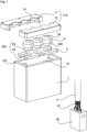
- FIG 1 shows a perspective exploded view of a cable bushing according to an embodiment of the invention with a Housing 1 with a cover 112, a counter-pressure plate 2 and several sealing elements 3 together with a suitable pre-assembled cable 4 with only a few reference numbers for the sake of clarity.
- the pre-assembled cable 4 includes a large number of strands 41, which are connected to a plug 40, and is for cable entry Fig. 1 suitable.
- a detailed description of the assembly of the cable gland with the cable 4 follows with reference to Figure 4a to d and Figure 5a to d and Figure 6a .
- the housing 1 includes an upper opening 10, which allows access to the interior of the housing 1 and is suitable for positioning the pre-assembled cable 4 with its plug 40 in the housing 1 in a simple manner as intended.
- the housing 1 also includes a cover 112 composed of two housing shells 11, 12 with a plurality of openings 14 for receiving a cable 4 and further cables 4 already positioned in the housing 1, a composite cover 112 placed on the opening 10 covering the opening 10 of the Housing 1 is closed.
- a support 102 for the counter-pressure plate 2 is provided near the opening 10.
- the counter-pressure plate 2 comprises a cable passage 234 with a cable inlet 24 and an opening 23, which allow a cable 4 that has already been positioned as intended in the housing 1 to be received.
- a sealing element 3 made of flexible and / or elastic material comprises an axial cable passage 34 with a slot 340, which starting from the cable passage 34 to a lateral edge of the sealing element 3.
- the sealing element 3 is designed to be suitable for receiving a cable 4 that has already been positioned as intended in the housing 1 by inserting it laterally through the slot 340 into its axial cable passage 34.
- a sealing element 3 arranged between the cover 112 and the counter-pressure plate 2 is also designed with a predetermined oversize compared to the cover 112 placed on the housing 1 and the counter-pressure plate 2 inserted into the housing 1, whereby it partially engages in a form-fitting manner in the opening 23 of the counter-pressure plate 2 and also a predetermined press and sealing connection between cable 4, sealing element 3, counter-pressure plate 2 and cover 112 is provided.
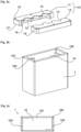
- Figure 2a shows the shell-shaped cover 112 of the housing 1 with its two housing shells 11 and 12, the parting plane of which runs centrally through the openings 14 for the cable 4 to pass through.
- the openings 14 of the cover 112 are conically expanded on the inside, starting from the edge of the openings 14 with the contour 13, in order to suitably cooperate with sealing elements 3, which will be described below with reference to Fig. 3a and b to be discribed.
- the cover 112 includes holes 15 suitable for screws.
- the sides of the two housing shells 11 and 12 corresponding to their parting plane are each designed as mutually corresponding contours 16, which interlock with each other in a form-fitting manner in such a way that the cover 112 is also sealed in the area of the parting plane.
- Cover 112 is made of a suitable plastic for this purpose.
- the cover 112 can include a further cord-like sealing element in the area of its parting plane.
- Figure 2b shows the housing 1 of Figure 1 with the opening 10 and a support 102 for the counter pressure plate 2
- Figure 2c shows a top view of the housing 1 of Figure 2b from above.
- the opening 10 has the edge 101 for placing the cover 112, which corresponds to the edge 111 of the cover 112.
- holes 105 are provided for fixing the cover 112 by means of screws, which correspond to the holes 15 in the cover 112.
- a support 102 suitable for the counter-pressure plate 2 is also provided in the housing 1 near the opening 10.
- the edition 102 of the execution of Figure 1 and 2 is designed for this purpose, for example, as two tiers, each of which extends over two opposite walls of the housing 1 and which partially continue on adjacent, also opposite walls.
- the edition 102 of the execution of Fig. 2b and c can also be designed as a projection which extends from the wall of the housing 1 by a predetermined amount into the interior of the housing 1, so that a stable positioning of the counter-pressure plate 2 on the support 102 is provided, and thereby also provides access to it Interior of the housing 1 is not affected by the opening 10 when inserting the pre-assembled cable 4.
- the edition 102 of the execution of Fig. 2b and c is particularly suitable for the one-piece counter-pressure plate 2 of the version Fig. 1 and 3c .
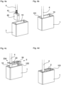
- Figure 3a shows an embodiment of a sealing element 3 from Figure 1 together with a sealing element 3 designed as a blind plug essentially include a first cylinder 31 with a first diameter on a second cylinder 32 with a second smaller diameter.
- the sealing element 3 includes the axial cable passage 34, from which the lateral slot 340 extends in the longitudinal direction through the first 31 and second 32 cylinders to the lateral edge of the sealing element 3.
- the elastic and/or flexible sealing element 3 can simply be opened radially to its axis via the slot 340, thereby exposing the cable passage 34 for the lateral insertion of the cable 4.
- the first cylinder 31 is designed to be rounded at the top in the vicinity of its opening 14 for suitable interaction with the cone 13 of the inner contour of the cover 112, which will also be described below with reference to Figure 6b and c is described.
- Figure 3b shows three sealing elements 3, which according to the embodiment of Figure 3a are designed and different than the individual sealing elements 3 of Figure 3a at the lower edge of the first cylinder 31 are connected to one another via a flat connection, for example a sealing element 3 can be designed as a blind plug.
- the connection of the sealing elements 3 only at the lower edge of their first cylinders 31 ensures that the sealing elements 3 are not impaired in their intended function by the connection.
- Figure 3c shows the counter pressure plate 2 of Figure 1 from above and Figure 3d a modification of the counter pressure plate 2 from Figure 3c , which are essentially two-dimensional with a predetermined thickness.
- the counter pressure plate 2 from Fig. 3c includes the cable outlets 234, each with a side cable inlet 24 and an opening 23, which allow a cable 4 that has already been positioned as intended in the housing 1 to be received.
- the extend Cable inlets 24 starting from the openings 23 each to a lateral edge of the counter-pressure plate 2, so that the openings 23 for the lateral insertion of a cable 4 are accessible via the cable inlets 24.
- the counter pressure plate 2 from Figure 3c is advantageously designed in one piece and is particularly suitable for the design of the housing 1 with the support 102 of Figure 2b and c.
- the counter pressure plate 2 from Figure 3d corresponds to the version of with its openings 23 Figure 3c , and is different from the counter pressure plate 2 of Figure 3c Like the cover 112, it is designed in two pieces and is composed of two essentially identical half-plates 20, 21, the parting plane of which runs centrally through the openings 23.
- the counter-pressure plate 2 has a cable passage 234 with a cable inlet 24 common to all openings 23, which is closed when its two half-plates 20, 21 are joined together.
- the counter pressure plate 2 from Figure 3d is for the design of the housing 1 with the support 102 of Figure 2b and c also suitable, whereby for a particularly stable and secure support, a correspondingly modified housing 1 can also include a closed support 102 that runs completely around its inner walls.
- the counter pressure plate 2 from Figure 3d is also particularly suitable for the design of the sealing elements 3 of Fig. 3b .
- the counter pressure plate 2 of the version Figure 3e comprises three individual plate elements 22, each provided with a cable passage 234, which essentially forms the counter-pressure plate 2 of Figure 3c corresponding counter pressure plate 2 can be assembled.
- the three plate elements 22 are essentially identical with their cable inlet 24 and their opening 23.
- the edges assigned to their respective adjacent plate elements 22 can suitably have contours that correspond to one another. This option is in Figure 3e each with dashed lines illustrated.
- the edges of the plate elements 22 can be designed, for example, in a dovetail-like or rail-like manner, so that a desirable cohesion of the plate elements 22 assembled to form the counter-pressure plate 2 is provided.
- a correspondingly modified housing 1 can also include a closed support 102 that runs completely around its inner walls.
- the sealing element 3 is under a press and sealing connection, the counter-pressure plate 2 being designed to be sufficiently stable to provide a counter-pressure on the sealing element 3, which also determines the material and the thickness of the counter-pressure plate 2.
- the counter-pressure plate 2 is suitably made of metal and the thickness of the counter-pressure plate 2 is of the design Figure 3d compared to the execution of Figure 3c increased in order to counteract pressure, particularly in the area of the parting plane of their half plates 20, 21.
- the area of the parting plane of the half-plates 20, 21 can also be designed to be stepped corresponding to one another, whereby the stability of a correspondingly assembled counter-pressure plate 2 is also increased in the area of the assembled gradations.
- the counter pressure plate 2 from Figure 3d can also be dimensioned in such a way that it rests directly on the edge 101 of the opening 10 of the housing 1, whereby the counter-pressure plate 2 can comprise a step, a contour or a profile on its edge, which is positively connected to the edge 101 of the housing 1 and /or the edge 111 of the Cover 112 corresponds. This possibility is indicated by the dashed line in Figure 3d indicated.
- further sealing measures can also be taken between the housing 1, the counter-pressure plate 2 and the cover 112 at their edges.
- such a counter-pressure plate 2 can also include suitable bores that correspond to the bores 15 and 105 of the cover 112 and the housing 1.
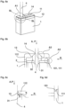
- Figures 4a to 4d show steps for assembling the cable gland Fig. 1 using the example of just a pre-assembled cable 4, where in Figure 1 the cable 4 is equipped with a plug 40 on its strands 41 and is inserted into the opening 10 of the housing 1 from above. In Figure 4b the plug 40 and the cable 4 are positioned at their predetermined position in the housing 1. The cable 4 protrudes from the housing 1.
- Figure 4c shows that outside the housing 1 via a cable inlet 24 of a cable passage 234 into an opening 23 of the counter-pressure plate 2 of Figure 1 and 3c inserted cable 4
- Figure 4d shows the counter-pressure plate 2 inserted as intended into the housing 1 on the support 102.
- the counter-pressure plate 2 is arranged near the opening 10 of the housing 1, and the edge 101 of the housing 1 protrudes upwards beyond the counter-pressure plate 2.
- the protruding edge 101 is desirable for the positioning of the counter-pressure plate 2 and for its interaction, in particular with the edge 111 of the cover 112.
- Figures 5a to 5d show further steps in assembling the cable gland Figure 1 following the steps of Figures 4a to 4d , where in Figure 5a , the cable 4 is inserted as intended via the slot 340 of a sealing element 3 into its axial cable passage 34.
- the other similar sealing elements 3 are designed as blind plugs without cable passage 34 and slot 340 to provide a suitable seal.
- the housing shells 11 and 12 are suitably positioned relative to the cable 4 so that they face the cover 112 of Figure 5d can be assembled, their contours 16 interlocking and the cable 4 being arranged in an opening 14 with its inside conical contour 13.
- the cover 112 is placed under pressure with its edge 111 onto the edge 101 of the opening 10 of the housing 1, with a pressing pressure P being exerted on the first cylinders 31 of the elastic and/or flexible sealing elements 3, which are designed with a predetermined oversize, and to them corresponding compression and development of its sealing effect.
- the cover 112 is fixed to the housing 1 by means of suitable screws (not shown) through the holes 15 and 105 of the cover 112 and housing 1, after which the fully assembled cable bushing of Figure 6a is provided.
- Figure 6b shows the above description of the installation of the cable gland with reference Figure 5d and 6a an enlarged view of section A1 of a longitudinal section through the line SL-SL of Figure 6a centrally along the axis of the cable 4, and Figure 6c shows an enlarged view of section A2 of Figure 6b .
- Figure 6d shows an enlarged view of section A3 of Fig. 6b with a modified design of the edge 101 of the housing 1, on which the edge 111 of the cover 112 rests, which is suitable for providing a further desirable seal of the housing 1, the edge 101 and the edge 111 each having corresponding, positively interlocking contours.
- a suitable sealing ring can also be provided in addition to or as an alternative to the above contour.
Description
Die Erfindung betrifft eine Kabeldurchführung eines insbesondere vorkonfektionierten elektrischen Kabels. Die Erfindung betrifft dabei außerdem insbesondere eine mit einer Dichtung versehene Kabeldurchführung in ein Gehäuse.The invention relates to a cable bushing of a particularly pre-assembled electrical cable. The invention also relates in particular to a cable feedthrough provided with a seal in a housing.
Beispielsweise der
Das ist jedoch verhältnismäßig umständlich und erfordert nach dem Durchführen des Kabels noch den zusätzlichen Arbeitsgang der Steckerbefestigung. Weiterhin müssen bei Kabeln mit vorkonfektionierten Steckern die Stecker für die Montage entfernt werden, was aufwendig zu handhaben und dementsprechend kostspielig ist.However, this is relatively complicated and requires the additional work of attaching the plug after the cable has been passed through. Furthermore, in the case of cables with pre-assembled connectors, the connectors have to be removed for assembly, which is difficult to handle and therefore expensive.
Die Kabeldurchführung der
Die
Die
Die
Die
Die
Der Schlitz des blockförmigen Einsatzes gestattet zwar ein Einführen des Kabels in das Kabel-Einlegeloch. Nachdem der Einsatz blockförmig ausgebildet ist und lediglich an seinem Rand unter lediglich zum Einsatzloch axialem Pressdruck von Gehäuse und Wand steht, ist der Schlitz des Einsatzes zur Sicherstellung der Dichtung zick-zack-förmig ausgebildet. Außerdem ist dabei die Dimension des Durchbruchs insbesondere in seiner Breite erheblich eingeschränkt. Auch bei mehreren Einsätzen lediglich am Rand eines Einsatzes ausgebildete keilförmige Ausprägungen, die mit entsprechenden Vorsprüngen der Haube zusammenwirken, bewirken lediglich einen Pressdruck auf den Rand eines benachbarten Einsatzes und haben somit keinen Einfluss auf die Dichtung der Haube, des Schlitzes und des Einlegelochs mit dem Kabel.The slot in the block-shaped insert allows the cable to be inserted into the cable insertion hole. Since the insert is block-shaped and only at its edge is under axial pressure from the housing and wall only towards the insert hole, the slot of the insert is designed in a zigzag shape to ensure the seal. In addition, the dimensions of the breakthrough are significantly limited, particularly in terms of its width. Even with several inserts, wedge-shaped formations formed only on the edge of an insert, which interact with corresponding projections on the hood, only cause a pressing pressure on the edge of an adjacent insert and therefore have no influence on the sealing of the hood, the slot and the insertion hole with the cable .
Der zick-zack-förmige Schlitz des Einsatzes erfordert außerdem eine sehr umständliche und dementsprechend kostspielige Handhabung beim Einführen des Kabels, nachdem der Einsatz dabei an dem Schlitz sowohl axial nach oben und unten als auch radial geöffnet werden muss, was zeitaufwendig und dementsprechend kostspielig ist. Außerdem ist die Kabeldurchführung der
Auch eine Kombination der Kabeldurchführung nach der
Aufgabe der Erfindung ist demnach, eine einfache und leicht handhabbare und montierbare und dementsprechend auch kostengünstige Kabeldurchführung für insbesondere vorkonfektionierte elektrische Kabel insbesondere in ein Gehäuse bereitzustellen. Dabei ist weiterhin Aufgabe eine entsprechende mit einer zuverlässigen Dichtung versehene Kabeldurchführung bereitzustellen, die außerdem für eine Vielzahl unterschiedlicher Gehäuse und Kabel geeignet ist.The object of the invention is therefore to provide a simple and easy-to-handle and assemble and accordingly also cost-effective cable bushing for, in particular, pre-assembled electrical cables, in particular in a housing. The further task is to provide a corresponding cable bushing with a reliable seal, which is also suitable for a large number of different housings and cables.
Die Aufgabe wird durch die kennzeichnenden Merkmale des unabhängigen Anspruchs 1 gelöst.The task is solved by the characterizing features of independent claim 1.
Vorteilhafte Ausgestaltungen der Erfindung sind in den Unteransprüchen und/oder der nachfolgenden Beschreibung angegeben.Advantageous embodiments of the invention are specified in the subclaims and/or the following description.
Die vorliegende Erfindung umfasst dabei insbesondere eine Kabeldurchführung für wenigstens ein Kabel in ein Gehäuse mit einer Öffnung, die mit einer wenigstens zwei Gehäuseschalen umfassenden Abdeckung mit wenigstens einer Öffnung versehen ist. Die Trennebene der Gehäuseschalen verläuft dabei mittig durch die Öffnung der Abdeckung, und zur Abdichtung des Gehäuses ist wenigstens ein elastisches und/oder flexibles Dichtelement vorgesehen, das einen Kabeldurchlass mit einem Schlitz zu seinem seitlichen Rand umfasst. Außerdem ist eine wenigstens einen Kabeldurchlass umfassende, die Öffnung des Gehäuses abdeckende Gegendruckplatte vorgesehen, die zur Abdichtung des Gehäuses mit dem Dichtelement und der Abdeckung zusammenwirkt, wobei das Dichtelement mit einem vorbestimmten Übermaß zwischen der Abdeckung und der Gegendruckplatte angeordnet ist und damit unter axialem Pressdruck steht. Das Dichtelement weist einen ersten Zylinder auf, der an der Gegendruckplatte aufliegt und in der Umgebung der Öffnung der Abdeckung abgerundet ausgebildet ist, und die Öffnung der Abdeckung ist ausgehend von einem Rand der Öffnung der Abdeckung innenseitig konusförmig erweitert, wodurch eine Kontur bereitgestellt ist, die mit der Abrundung des Dichtelements derart zusammenwirkt, dass das Dichtelement unter dem Pressdruck und unter einer axialen und radialen Kompression ohne Auftreten einer Scherkraft die Abdichtung insbesondere des Kabels, der Abdeckung und seines Schlitzes bereitstellt.The present invention particularly includes a cable feedthrough for at least one cable into a housing with an opening, which is provided with a cover comprising at least two housing shells and having at least one opening. The parting plane of the housing shells runs centrally through the opening of the cover, and at least one elastic and/or flexible sealing element is provided to seal the housing, which includes a cable passage with a slot towards its side edge. In addition, a counter-pressure plate comprising at least one cable passage and covering the opening of the housing is provided, which cooperates with the sealing element and the cover to seal the housing, the sealing element having a predetermined Oversize is arranged between the cover and the counter-pressure plate and is therefore under axial pressing pressure. The sealing element has a first cylinder which rests on the counter-pressure plate and is rounded in the vicinity of the opening of the cover, and the opening of the cover is conically widened on the inside starting from an edge of the opening of the cover, thereby providing a contour which cooperates with the rounding of the sealing element in such a way that the sealing element provides the seal in particular of the cable, the cover and its slot under the pressing pressure and under axial and radial compression without the occurrence of a shear force.
Die Vorsehung der die Öffnung des Gehäuses abdeckenden Gegendruckplatte ist besonders vorteilhaft, nachdem die Gegendruckplatte dem Pressdruck über die gesamte Öffnung insbesondere auch in ihrem zentralen Bereich entgegenwirkt, so dass mittels dem Dichtelement eine über die ganze Öffnung wirkungsvolle Dichtung bereitgestellt ist. Außerdem ist aufgrund der Vorsehung der Gegendruckplatte die Öffnung des Gehäuses nicht in ihrer Dimensionierung beschränkt, so dass ein Zugang auch für eine Vielzahl von mit Steckern beträchtlicher Abmessungen vorkonfektionierte Kabel in das Innere des Gehäuses sichergestellt ist. Die erfindungsgemäße Kabeldurchführung ist somit für eine Vielzahl unterschiedlicher Gehäuse und Kabel flexibel anpassbar und handhabbar.The provision of the counter-pressure plate covering the opening of the housing is particularly advantageous since the counter-pressure plate counteracts the pressing pressure over the entire opening, especially in its central area, so that an effective seal is provided over the entire opening by means of the sealing element. In addition, due to the provision of the counter-pressure plate, the opening of the housing is not limited in its dimensions, so that access to the interior of the housing is also ensured for a large number of cables pre-assembled with plugs of considerable dimensions. The cable bushing according to the invention can therefore be flexibly adapted and handled for a large number of different housings and cables.
Für eine handhabbare Einführung des Kabels nach erfolgter bestimmungsgemäßer Positionierung des Kabels in dem Gehäuse kann der Kabeldurchlass der Gegendruckplatte hierbei geeigneter Weise wenigstens eine durchgehende Öffnung und wenigstens einen seitlichen Kabeleinlass zur seitlichen Einführung des Kabels in die Öffnung umfassen.For a manageable insertion of the cable after the cable has been correctly positioned in the housing, the cable passage of the counter-pressure plate can suitably comprise at least one continuous opening and at least one lateral cable inlet for the lateral insertion of the cable into the opening.
Weiterhin kann die Gegendruckplatte geeigneter Weise in der Umgebung der Öffnung des Gehäuses auf einer innenseitig an einer Wand des Gehäuses ausgebildeten Auflage aufliegen, die ein Vorsprung sein kann, der um einen vorbestimmten Betrag in das Innere des Gehäuses ragt, so dass eine stabile Positionierung der Gegendruckplatte auf der Auflage bereitgestellt ist und dabei außerdem der Zugang in das Innere des Gehäuses durch dessen Öffnung nicht beeinträchtigt ist. An Stelle des Vorsprungs kann die Auflage auch als Stufung an einer Wand des Gehäuses ausgebildet sein. Für die stabile Positionierung der Gegendruckplatte in dem Gehäuse und der Abdeckung auf dem Gehäuse ragt ein die Öffnung umgebender Rand des Gehäuses dabei geeigneter Weise über die Gegendruckplatte hinaus.Furthermore, the counter-pressure plate can suitably rest in the vicinity of the opening of the housing on a support formed on the inside of a wall of the housing, which can be a projection that projects into the interior of the housing by a predetermined amount, so that a stable positioning of the counter-pressure plate is provided on the support and also provides access to the interior of the Housing is not affected by its opening. Instead of the projection, the support can also be designed as a step on a wall of the housing. For the stable positioning of the counter-pressure plate in the housing and the cover on the housing, an edge of the housing surrounding the opening protrudes suitably beyond the counter-pressure plate.
Dabei kann die Gegendruckplatte insbesondere vorteilhaft einstückig ausgebildet sein, wonach sie besonders einfach zu handhaben ist und außerdem gegenüber einem insbesondere auf ihren zentralen Bereich wirkenden Druck besonders stabil ist.The counter-pressure plate can particularly advantageously be designed in one piece, after which it is particularly easy to handle and is also particularly stable in relation to pressure acting in particular on its central area.
Nach einer Abwandlung der vorstehenden Ausführung kann die Gegendruckplatte zweistückig ausgebildet sein und sich aus zwei im Wesentlichen identisch ausgebildeten Halbplatten zusammensetzen, deren Trennebene mittig durch ihre Öffnung verläuft. Eine derartige zweistückige Gegendruckplatte ist dabei zur Bereitstellung eines stabilen Gegendrucks insbesondere im Bereich ihrer Trennebene mit einer entsprechenden Mächtigkeit (Dicke) ausgebildet. In dem Bereich der Trennebene können die Halbplatten auch miteinander korrespondierend abgestuft ausgebildet sein, wodurch die Stabilität einer entsprechend zusammengesetzten Gegendruckplatte ebenfalls erhöht ist.According to a modification of the above embodiment, the counter-pressure plate can be designed in two pieces and can be composed of two essentially identical half-plates, the parting plane of which runs centrally through its opening. Such a two-piece counter-pressure plate is designed to provide a stable counter-pressure, particularly in the area of its parting plane, with a corresponding thickness (thickness). In the area of the parting plane, the half-plates can also be designed to be stepped corresponding to one another, which also increases the stability of a correspondingly assembled counter-pressure plate.
Nach einer weiteren Abwandlung kann die Gegendruckplatte aus einer Vielzahl von individuellen im Wesentlichen identisch ausgebildeten Plattenelementen mit jeweils wenigstens einem Kabeldurchlass zur Aufnahme eines Kabels zusammensetzbar ausgebildet sein. Dabei kann ein jeweils mit einem bestimmungsgemäß benachbarten Plattenelement korrespondierender Rand eines Plattenelements geeigneter Weise eine mit dem Rand des benachbarten Plattenelements korrespondierende Kontur aufweisen, wobei die Konturen beispielsweise schwalbenschwanzartig oder schienenartig korrespondierend ausgebildet sein können, so dass ein wünschenswerter Zusammenhalt der zu der Gegendruckplatte zusammengesetzten Plattenelemente bereitgestellt ist.According to a further modification, the counter-pressure plate can be designed to be assembled from a plurality of individual, essentially identically designed plate elements, each with at least one cable passage for receiving a cable. In this case, an edge of a plate element that corresponds to an intended adjacent plate element can suitably have a contour that corresponds to the edge of the adjacent plate element, the contours being designed, for example, to correspond in a dovetail-like or rail-like manner can be, so that a desirable cohesion of the plate elements assembled to form the counter-pressure plate is provided.
Die Öffnung der Abdeckung des Gehäuses ist besonders vorteilhaft ausgehend von ihrem Rand innenseitig konusförmig erweitert, wodurch eine Kontur bereitgestellt ist, die mit dem Dichtelement derart zusammenwirkt, dass das Dichtelement unter dem Pressdruck eine axiale und radiale Kompression erfährt, ohne dass dabei unerwünschte Scherkräfte auftreten. Durch diese Maßnahme wird eine besonders wirkungsvolle und zuverlässige Dichtung zwischen dem Kabel, dem Dichtelement und der Abdeckung erreicht, und außerdem der Schlitz des Dichtelements wünschenswert dicht verschlossen.The opening of the cover of the housing is particularly advantageously expanded conically on the inside starting from its edge, whereby a contour is provided which interacts with the sealing element in such a way that the sealing element experiences axial and radial compression under the pressing pressure without undesirable shear forces occurring. This measure achieves a particularly effective and reliable seal between the cable, the sealing element and the cover, and also desirably closes the slot of the sealing element tightly.
Hierbei können geeignete Maßnahmen zur stabilen Fixierung der Abdeckung auf dem Gehäuse wie auch zur stabilen Zusammensetzung der Gehäuseschalen zu der Abdeckung vorgesehen sein. Geeigneter Weise können Gehäuse und Abdeckung und die Gehäuseschalen hierfür miteinander verrastbar ausgebildet sein. Die Abdeckung und das Gehäuse können auch miteinander verschraubt werden, wofür geeignete Bohrungen in dem Gehäuse und der Abdeckung vorgesehen sein können.In this case, suitable measures can be provided for the stable fixation of the cover on the housing as well as for the stable assembly of the housing shells to form the cover. Suitably, the housing and cover and the housing shells can be designed so that they can be locked together. The cover and the housing can also be screwed together, for which suitable holes can be provided in the housing and the cover.
In die Öffnung der aus zwei Gehäuseschalen bestehenden Abdeckung kann auch ein bereits bestimmungsgemäß in dem Gehäuse positioniertes Kabel auf einfache Weise zwischen die beiden getrennten Gehäuseschalen eingeführt werden, wonach die beiden Gehäuseschalen zu der Abdeckung mit dem in ihre Öffnung eingeführten Kabel zusammengesetzt werden. Die mit der Trennebene der Gehäuseschalen korrespondierenden Seiten der beiden Gehäuseschalen können dabei geeigneter Weise als jeweils miteinander korrespondierende Konturen ausgebildet sein, die formschlüssig derart ineinandergreifen, dass die Abdeckung auch im Bereich der Trennebene ihrer Gehäuseschalen abgedichtet ist.In the opening of the cover consisting of two housing shells, a cable already positioned in the housing as intended can also be easily inserted between the two separate housing shells, after which the two housing shells are assembled to form the cover with the cable inserted into their opening. The sides of the two housing shells corresponding to the parting plane of the housing shells can be suitably designed as contours that correspond to one another and which interlock with each other in a form-fitting manner in such a way that the cover is also sealed in the area of the parting plane of their housing shells.
Das Dichtelement kann vorteilhaft den ersten Zylinder mit einem ersten Durchmesser und einen zweiten Zylinder mit einem zweiten kleineren Durchmesser umfassen, wobei der Kabeldurchlass axial durch den ersten und zweiten Zylinder ausgebildet ist, und der Schlitz sich vorteilhaft in Längsrichtung durch den ersten und zweiten Zylinder zu dem seitlichen Rand des Dichtelements erstreckt. Auf diese Weise ist das Dichtelement besonders einfach handhabbar, da es geeignet ausgebildet ist, ein bereits in dem Gehäuse positioniertes Kabel durch einfaches seitliches Einführen mittels einfach handhabbarer lediglich radialer Öffnung seines Schlitzes in seinen hierdurch freigelegten Kabeldurchlass einzuführen. Die vorteilhafte Ausbildung des Schlitzes in Längsrichtung ist insbesondere möglich, nachdem wie eingangs gesagt mittels der erfindungsgemäßen Kabeldurchführung eine vorteilhafte Kompression des Dichtelements ohne Auftreten von unerwünschten, die Abdichtung des Schlitzes möglicher Weise beeinträchtigenden Scherkräften, bereitgestellt wird.The sealing element can advantageously comprise the first cylinder with a first diameter and a second cylinder with a second smaller diameter, the cable passage being formed axially through the first and second cylinders, and the slot advantageously extending in the longitudinal direction through the first and second cylinders lateral edge of the sealing element extends. In this way, the sealing element is particularly easy to handle, since it is designed to be suitable for inserting a cable that is already positioned in the housing into its thereby exposed cable passage by simply inserting it from the side using an easy-to-handle, merely radial opening of its slot. The advantageous design of the slot in the longitudinal direction is possible in particular after, as stated at the beginning, an advantageous compression of the sealing element is provided by means of the cable bushing according to the invention without the occurrence of undesirable shear forces that may impair the sealing of the slot.
Der erste Zylinder des Dichtelements kann geeigneter Weise an der Gegendruckplatte aufliegen und vorteilhaft in der Umgebung der Öffnung der Abdeckung abgerundet ausgebildet sein, wodurch das Dichtelement besonders vorteilhaft mit der vorstehend beschriebenen konusförmig erweiterten Öffnung der Abdeckung zusammenwirkt, so dass das Dichtelement unter dem axialen Pressdruck der Abdeckung eine axiale und radiale Kompression erfährt.The first cylinder of the sealing element can suitably rest on the counter-pressure plate and can advantageously be rounded in the vicinity of the opening of the cover, whereby the sealing element cooperates particularly advantageously with the conically enlarged opening of the cover described above, so that the sealing element is under the axial pressing pressure of the Cover experiences axial and radial compression.
Der zweite Zylinder des Dichtelements kann zur einfachen Handhabung und Montage geeigneter Weise formschlüssig mit der Öffnung der Gegendruckplatte in der Öffnung angeordnet sein, wodurch das Dichtelement außerdem stabil auf der Gegendruckplatte positioniert ist.For easy handling and assembly, the second cylinder of the sealing element can be arranged in a form-fitting manner with the opening of the counter-pressure plate in the opening, whereby the sealing element is also stably positioned on the counter-pressure plate.
Das Gehäuse einer vorstehend beschriebenen Kabeldurchführung kann aus Kunststoff und/oder Metall und die Abdeckung geeigneter Weise aus Kunststoff sein, nachdem die Abdeckung aus zwei formschlüssig korrespondierenden Gehäuseschalen zusammengesetzt ist. Die Gegendruckplatte kann, um einem vorstehend beschriebenen Pressdruck wünschenswert entgegenzuwirken geeigneter Weise aus Metall mit einer vorbestimmten Mächtigkeit (Dicke) ausgebildet sein. Das Dichtelement ist vorteilhaft einstückig aus einem geeigneten flexiblen und/oder elastischen dichtenden Material ausgebildet, wobei das Dichtelement auch als Blindstopfen ohne den Kabeldurchlass und den Schlitz ausgebildet sein kann.The housing of a cable bushing described above can be made of plastic and/or metal and the cover can be made of a suitable type Be plastic after the cover is composed of two form-fitting corresponding housing shells. In order to desirably counteract a pressing pressure described above, the counter-pressure plate can be suitably formed from metal with a predetermined thickness (thickness). The sealing element is advantageously formed in one piece from a suitable flexible and/or elastic sealing material, whereby the sealing element can also be designed as a blind plug without the cable passage and the slot.
Eine vorstehend beschriebene erfindungsgemäße Kabeldurchführung ist insbesondere geeignet für wenigstens ein vorkonfektioniertes elektrisches Kabel, das mit einem Stecker versehen sein kann, wobei wünschenswert ist, insbesondere den Stecker vor Montage der Kabeldurchführung bestimmungsgemäß in dem Gehäuse zu positionieren.A cable bushing according to the invention described above is particularly suitable for at least one pre-assembled electrical cable, which can be provided with a plug, it being desirable in particular to position the plug properly in the housing before installing the cable bushing.
Eine erfindungsgemäße Kabeldurchführung kann außerdem für eine Vielzahl von Kabeln ausgelegt sein.A cable bushing according to the invention can also be designed for a large number of cables.
Eine erfindungsgemäße Kabeldurchführung ist wie vorstehend beschrieben auf einfache Weise handhabbar und montierbar und dementsprechend auch kostengünstig und gestattet eine zuverlässige Dichtung und flexible Verwendung mit einer Vielzahl von unterschiedlich ausgebildeten Kabeln und Gehäusen.As described above, a cable bushing according to the invention can be handled and assembled in a simple manner and is therefore also cost-effective and allows a reliable seal and flexible use with a large number of differently designed cables and housings.
Ausführungsbeispiele der Erfindung sind in den Zeichnungen dargestellt und werden im Folgenden näher erläutert. Es zeigen:
- Fig. 1
- eine perspektivische Explosionsdarstellung einer Kabeldurchführung einer Ausführung der Erfindung mit einem Gehäuse mit einer Abdeckung, einer Gegendruckplatte und Dichtelementen und mit einem vorkonfektionierten Kabel;
- Fig. 2a
- die Abdeckung von
Fig. 1 ; - Fig. 2b
- das Gehäuse von
Fig. 1 ; - Fig. 2c
- das Gehäuse von
Fig. 1 von oben; - Fig. 3a
- Ausführungen eines individuellen Dichtelements der Ausführung von
Fig. 1 ; - Fig. 3b
- eine Abwandlung des Dichtelements von
Fig. 3a ; - Fig. 3c
- die Gegendruckplatte von
Fig. 1 von oben; - Fig. 3d
- eine Abwandlung der Gegendruckplatte von
Fig. 3c ; - Fig. 3e
- eine weitere Abwandlung der Gegendruckplatte von
Fig. 3c ; - Fig. 4a bis d
- Schritte bei der Montage der Kabeldurchführung von
Fig. 1 ; - Fig. 5a bis d
- weitere Schritte bei der Montage der Kabeldurchführung von
Fig. 1 ; - Fig. 6a
- die vollständig montierte Kabeldurchführung von
Fig. 1 ; - Fig. 6b
- eine vergrößerte Darstellung des Ausschnitts A1 eines Schnitts entlang der Linie SL-SL von
Fig. 6a ; - Fig. 6c
- eine vergrößerte Darstellung des Ausschnitts A2 von
Fig. 6b ; und - Fig. 6d
- eine vergrößerte Darstellung des Ausschnitts A3 von
Fig. 6b mit einem abgewandelten Gehäuse.
- Fig. 1
- a perspective exploded view of a cable bushing of an embodiment of the invention a housing with a cover, a counter-pressure plate and sealing elements and with a pre-assembled cable;
- Fig. 2a
- the cover of
Fig. 1 ; - Fig. 2b
- the housing of
Fig. 1 ; - Fig. 2c
- the housing of
Fig. 1 from above; - Fig. 3a
- Versions of an individual sealing element of the version of
Fig. 1 ; - Fig. 3b
- a modification of the sealing element from
Fig. 3a ; - Fig. 3c
- the counter pressure plate of
Fig. 1 from above; - Fig. 3d
- a modification of the counter pressure plate from
Fig. 3c ; - Fig. 3e
- another modification of the counter pressure plate
Fig. 3c ; - Fig. 4a to d
- Steps for assembling the cable gland
Fig. 1 ; - Fig. 5a to d
- further steps in assembling the cable gland
Fig. 1 ; - Fig. 6a
- the fully assembled cable gland from
Fig. 1 ; - Fig. 6b
- an enlarged view of detail A1 of a section along the line SL-SL of
Fig. 6a ; - Fig. 6c
- an enlarged view of section A2 of
Fig. 6b ; and - Fig. 6d
- an enlarged view of section A3 from
Fig. 6b with a modified housing.
Die Figuren enthalten teilweise vereinfachte, schematische Darstellungen. Zum Teil werden für gleiche, aber gegebenenfalls nicht identische Elemente identische Bezugszeichen verwendet. Verschiedene Ansichten gleicher Elemente könnten unterschiedlich skaliert sein.The figures contain partly simplified, schematic representations. In some cases, identical reference numbers are used for identical but possibly not identical elements. Different views of the same elements could be scaled differently.
Das vorkonfektionierte Kabel 4 umfasst eine Vielzahl von Litzen 41, die mit einem Stecker 40 verbunden sind, und ist für die Kabeldurchführung von
Das Gehäuse 1 umfasst eine obere Öffnung 10, die einen Zugang in das Innere des Gehäuses 1 gestattet und geeignet ist, das vorkonfektionierte Kabel 4 mit seinem Stecker 40 auf einfache Weise bestimmungsgemäß in dem Gehäuse 1 zu positionieren. Das Gehäuse 1 umfasst außerdem eine aus zwei Gehäuseschalen 11, 12 zusammengesetzte Abdeckung 112 mit mehreren Öffnungen 14 zur Aufnahme eines bereits in dem Gehäuse 1 positionierten Kabels 4 und weiterer Kabel 4, wobei eine zusammengesetzte und auf die Öffnung 10 aufgesetzte Abdeckung 112 die Öffnung 10 des Gehäuses 1 verschließt.The housing 1 includes an
Innerhalb des Gehäuses 1 ist in der Nähe der Öffnung 10 eine Auflage 102 für die Gegendruckplatte 2 vorgesehen. Die Gegendruckplatte 2 umfasst einen Kabeldurchlass 234 mit einem Kabeleinlass 24 und einer Öffnung 23, die es gestatten, ein bereits bestimmungsgemäß in dem Gehäuse 1 positioniertes Kabel 4 aufzunehmen.Within the housing 1, a
Ein Dichtelement 3 aus flexiblem und/oder elastischem Material umfasst einen axialen Kabeldurchlass 34 mit einem Schlitz 340, der sich ausgehend von dem Kabeldurchlass 34 zu einem seitlichen Rand des Dichtelements 3 erstreckt. Auf diese Weise ist das Dichtelement 3 geeignet ausgebildet, ein bereits bestimmungsgemäß in dem Gehäuse 1 positioniertes Kabel 4 mittels dessen seitlichen Einführens durch den Schlitz 340 in seinen axialen Kabeldurchlass 34 aufzunehmen. Ein zwischen der Abdeckung 112 und der Gegendruckplatte 2 angeordnetes Dichtelement 3 ist außerdem gegenüber der auf das Gehäuse 1 aufgesetzten Abdeckung 112 und der in das Gehäuse 1 eingesetzten Gegendruckplatte 2 mit einem vorbestimmten Übermaß ausgebildet, wobei es teilweise in die Öffnung 23 der Gegendruckplatte 2 formschlüssig eingreift und außerdem eine vorbestimmte Press- und Dichtverbindung zwischen Kabel 4, Dichtelement 3, Gegendruckplatte 2 und Abdeckung 112 bereitgestellt ist.A sealing
Geeigneter Weise sind die mit ihrer Trennebene korrespondierenden Seiten der beiden Gehäuseschalen 11 und 12 jeweils als miteinander korrespondierende Konturen 16 ausgebildet, die formschlüssig derart ineinandergreifen, dass die Abdeckung 112 auch im Bereich der Trennebene abgedichtet ist. Zur Bereitstellung einer besonders zuverlässigen Dichtung der beiden Gehäuseschalen 11 und 12 ist die Abdeckung 112 hierfür aus einem geeigneten Kunststoff ausgebildet. Zusätzlich oder alternativ kann die Abdeckung 112 dabei im Bereich ihrer Trennebene ein weiteres schnurartiges Dichtelement umfassen.Suitably, the sides of the two
Die Auflage 102 der Ausführung von
Die Gegendruckplatte 2 von
Die Gegendruckplatte 2 von
Die Gegendruckplatte 2 der Ausführung von
Wie vorstehend unter Bezugnahme auf
Die Gegendruckplatte 2 von
In
In
Die Abdeckung 112 wird mittels geeigneter nicht dargestellter Schrauben durch die Bohrungen 15 und 105 von Abdeckung 112 und Gehäuse 1 an dem Gehäuse 1 fixiert, wonach die vollständig montierte Kabeldurchführung von
Bei der Montage der zusammengesetzten Abdeckung 112 auf das Gehäuse 1 wird ein axialer Druck P von oben auf das flexible und/oder elastische Dichtelement 3 ausgeübt, wobei dieser Druck P insbesondere in Zusammenwirken mit dem innenseitigen Konus 13 der Abdeckung 112 und der Abrundung des ersten Zylinders 31 eine vorteilhaft sowohl axiale A als auch radiale R Kompression K des Dichtelements 3 erzeugt, so dass mittels dem Dichtelement 3 eine wünschenswerte Abdichtung der Abdeckung 112, des Kabels 4 in dem Kabeldurchlass 34 und dem Schlitz 340 bereitgestellt ist.When assembling the assembled
Das vorstehende Ausführungsbeispiel wurde beispielhaft anhand einer für maximal drei Kabel 4 ausgelegten Kabeldurchführung mit entsprechend drei Dichtelementen 3, etc. beschrieben. Es ist klar, dass weitere Ausführungen auch für mehr oder weniger Kabel 4 ausgelegt sein können.The above exemplary embodiment was described as an example using a cable bushing designed for a maximum of three
Auch wenn in den Figuren verschiedene Aspekte oder Merkmale der Erfindung jeweils in Kombination gezeigt sind, ist für den Fachmann - soweit nicht anders angegeben - ersichtlich, dass die dargestellten und diskutierten Kombinationen nicht die einzig möglichen sind. Insbesondere können einander entsprechende Einheiten oder Merkmalskomplexe aus unterschiedlichen Ausführungsbeispielen miteinander ausgetauscht werden.Even if various aspects or features of the invention are shown in combination in the figures, it will be apparent to the person skilled in the art - unless otherwise stated - that the combinations shown and discussed are not the only possible ones. In particular, corresponding units or feature complexes from different exemplary embodiments can be exchanged with one another.
- 11
- GehäuseHousing
- 1010
- Öffnungopening
- 101101
- Randedge
- 102102
- Auflage (Vorsprung, Stufung)Edition (projection, gradation)
- 11, 1211, 12
- GehäuseschaleHousing shell
- 112112
- Abdeckungcover
- 111111
- Randedge
- 1313
- Kontur, Konuscontour, cone
- 1414
- Öffnungopening
- 1515
- Bohrungdrilling
- 1616
- Kontur (Trennebene)Contour (parting plane)
- 22
- Gegendruckplattecounter pressure plate
- 20, 2120, 21
- HalbplatteHalf plate
- 2222
- PlattenelementPlate element
- 2323
- Öffnungopening
- 2424
- KabeleinlassCable inlet
- 234234
- KabeldurchlassCable passage
- 33
- DichtelementSealing element
- 3131
- erster Zylinderfirst cylinder
- 3232
- zweiter Zylindersecond cylinder
- 3434
- KabeldurchlassCable passage
- 340340
- Schlitzslot
- 44
- KabelCable
- 4040
- SteckerPlug
- 4141
- Litzestrand
- A1, A2, A3A1, A2, A3
- AusschnittDetail
- AA
- AxialAxial
- RR
- RadialRadial
- PP
- DruckPressure
- KK
- Kompressioncompression
- SLSL
- Schnittliniecutting line
Claims (12)
- Cable leadthrough for at least one cable (4) into a housing (1) with an opening (10), which cable leadthrough is provided with a cover (112) comprising at least two housing shells (11, 12) and with at least one opening (14), whereina separating plane of the housing shells (11, 12) extends centrally through the opening (14); and wherein,for sealing off the housing (1), provision is made of at least one elastic and/or flexible sealing element (3) which comprises a cable passage (34) with a slot (340) to its lateral edge, wherein provision is made of a counterpressure plate (2) which comprises at least one cable passage (234) and which covers the opening (10) and which, for sealing off the housing (1), interacts with the sealing element (3) and the cover (112), whereinthe sealing element (3) is arranged with a predetermined oversize between the cover (112) and the counterpressure plate (2) and is subjected to axial pressing pressure (P), wherein the sealing element (3) has a first cylinder (31) which bears on the counterpressure plate (2) and which is rounded in vicinity of the opening (14) of the cover (112), and whereinthe opening (14) of the cover (112), proceeding from an edge of the opening (14), is conically widened at the inner side, whereby provision is made of a contour (13) which interacts with the rounding of the sealing element (3) in such a way that, under the pressing force (P), the sealing element (3) undergoes an axial (A) and radial (R) compression (K) without the occurrence of shear force.
- Cable leadthrough according to Claim 1,
characterized in that
the cable passage (234) of the counterpressure plate (2) comprises at least one continuous opening (23) and at least one lateral cable inlet (24) for lateral insertion of the cable (4) into the opening (23) . - Cable leadthrough according to Claim 1 or 2,
characterized in that
a support (102) is formed in the vicinity of the opening (10) at the inner side of a wall of the housing (1), on which support the counterpressure plate (2) bears. - Cable leadthrough according to one of the preceding Claims 1 to 3,
characterized in that
the counterpressure plate (2) is formed in one piece. - Cable leadthrough according to one of Claims 1 to 3,
characterized in that
the counterpressure plate (2) is formed in two pieces and is made up of two half-plates (20, 21) which are of substantially identical form and whose separating plane extends centrally through the opening (23) of the counterpressure plate (2). - Cable leadthrough according to one of the preceding Claims 1 to 3,
characterized in that
the counterpressure plate (2) is made up of a plurality of individual plate elements (22) with in each case at least one cable passage (234). - Cable leadthrough according to one of the preceding Claims 1 to 6,
characterized in that
those sides of the two housing shells (11, 12) which correspond to the separating plane of the housing shells (11, 12) are each formed as mutually corresponding contours (16) which interengage with a form fit in such a way that the cover (112) is sealed off in the region of the separating plane too. - Cable leadthrough according to one of the preceding Claims 1 to 7,
characterized in that
the sealing element (3) comprises the first cylinder (31), with a first diameter, and a second cylinder (32), with a second, smaller diameter, wherein the cable passage (34) is formed axially through the first cylinder (31) and second cylinder (32), and the slot (340) extends to a lateral edge of the sealing element (3) in a longitudinal direction through the first cylinder (31) and second cylinder (32) . - Cable leadthrough according to Claim 8,
characterized in that
the second cylinder (32) is arranged in the opening (23) of the counterpressure plate (2) so as to have a form fit with the opening (23). - Cable leadthrough according to one of the preceding Claims 1 to 9,
characterized in that
the cable (4) is a prefabricated electrical cable (4) which may be provided with a plug (40). - Cable leadthrough according to one of the preceding Claims 1 to 10,
characterized in thatthe housing (1) is formed from plastic and/or metal, and the cover (112) is formed from plastic, and the counterpressure plate (2) is formed from plastic and preferably from metal with a predetermined size (thickness), andthe sealing element (3) is formed in one piece from a suitable flexible and/or elastic sealing material. - Cable leadthrough according to one of the preceding Claims 1 to 11, wherein the sealing element (3) is designed as a blind plug without the cable passage (34) and the slot (340).
Applications Claiming Priority (3)
| Application Number | Priority Date | Filing Date | Title |
|---|---|---|---|
| DE102017127774 | 2017-11-24 | ||
| DE102017129923.8A DE102017129923A1 (en) | 2017-11-24 | 2017-12-14 | Grommet |
| PCT/DE2018/100930 WO2019101268A1 (en) | 2017-11-24 | 2018-11-14 | Cable feedthrough |
Publications (2)
| Publication Number | Publication Date |
|---|---|
| EP3714520A1 EP3714520A1 (en) | 2020-09-30 |
| EP3714520B1 true EP3714520B1 (en) | 2024-02-21 |
Family
ID=66442086
Family Applications (1)
| Application Number | Title | Priority Date | Filing Date |
|---|---|---|---|
| EP18815508.9A Active EP3714520B1 (en) | 2017-11-24 | 2018-11-14 | Cable feedthrough |
Country Status (5)
| Country | Link |
|---|---|
| US (1) | US11038333B2 (en) |
| EP (1) | EP3714520B1 (en) |
| CN (1) | CN111373618B (en) |
| DE (1) | DE102017129923A1 (en) |
| WO (1) | WO2019101268A1 (en) |
Families Citing this family (8)
| Publication number | Priority date | Publication date | Assignee | Title |
|---|---|---|---|---|
| WO2021186534A1 (en) * | 2020-03-17 | 2021-09-23 | 三菱電機株式会社 | Circuit box |
| US11505953B1 (en) * | 2020-04-30 | 2022-11-22 | Concrete Voids LLC | Concrete beam conduit guide |
| US11510331B2 (en) * | 2020-09-10 | 2022-11-22 | Dell Products, L.P. | Profile-modeling cable clip for sealing airflow in an information handling system (IHS) chassis |
| GB2600950A (en) * | 2020-11-12 | 2022-05-18 | Continental Automotive Gmbh | Electronic assembly and method of producing the same |
| CN112706632A (en) * | 2020-12-23 | 2021-04-27 | 中车永济电机有限公司 | Sealing structure of charger cabinet |
| US20220349498A1 (en) * | 2021-04-29 | 2022-11-03 | APG Vision LLC | Ball Mount with Integrated Cable Gland |
| CN113328358A (en) * | 2021-05-18 | 2021-08-31 | 中国建筑第八工程局有限公司 | Plugging device for joint of distribution box and bridge and using method thereof |
| DE102021122931A1 (en) * | 2021-09-06 | 2023-03-09 | Endress+Hauser Flowtec Ag | Electrical feedthrough and electronics housing |
Citations (5)
| Publication number | Priority date | Publication date | Assignee | Title |
|---|---|---|---|---|
| JPS57161282U (en) * | 1981-04-02 | 1982-10-09 | ||
| DE19723032C1 (en) * | 1997-06-02 | 1998-10-01 | Harting Kgaa | Sealed lead-in unit for electrical cables in switching equipment with slotted sealing element |
| EP0901190A2 (en) * | 1997-09-06 | 1999-03-10 | Rose-Elektrotechnik GmbH + Co KG Elektrotechnische Fabrik | Cable-plug-leadthrough system |
| DE29911305U1 (en) * | 1999-06-29 | 1999-11-04 | Rose Elektrotech Gmbh | Cable-connector bushing system |
| DE102010046857B3 (en) * | 2010-09-29 | 2011-12-15 | Adc Gmbh | Cable gland and method for passing a cable through an opening in a wall or floor panel |
Family Cites Families (18)
| Publication number | Priority date | Publication date | Assignee | Title |
|---|---|---|---|---|
| DE20217273U1 (en) * | 2002-11-09 | 2003-01-16 | Harting Electric Gmbh & Co Kg | Fastening device for connectors |
| DE10350433A1 (en) * | 2003-10-29 | 2005-07-07 | Krone Gmbh | wall outlet |
| DE102006062609A1 (en) | 2005-07-28 | 2008-07-03 | Hidde, Axel R., Dr. | Cable feedthrough and/or insertion component for mechanical sealing and/or clamping and electrical shielding and/or conducting in e.g. breathable or non-breathable cable, has sections sealing and/or clamping, conducting and shielding cable |
| DE202005020026U1 (en) * | 2005-12-22 | 2006-03-16 | Harting Electric Gmbh & Co. Kg | Holding frame for plug-in modules |
| JP2008028267A (en) * | 2006-07-24 | 2008-02-07 | Fanuc Ltd | Sealing structure of electric circuit unit |
| US7411128B2 (en) * | 2006-09-26 | 2008-08-12 | Lapp Engineering & Co. | Cable feed-through and cable feed-through system |
| DE102008022908B4 (en) * | 2008-05-09 | 2014-11-27 | Yamaichi Electronics Deutschland Gmbh | Junction box, uses a junction box and procedures |
| DE102011103351B3 (en) * | 2011-05-27 | 2012-09-13 | Phoenix Contact Gmbh & Co. Kg | Sealing element and connection housing with a sealing element |
| DE202012101639U1 (en) * | 2012-05-03 | 2013-08-06 | Weidmüller Interface GmbH & Co. KG | Through housing |
| US9121244B2 (en) * | 2012-06-14 | 2015-09-01 | Schlumberger Technology Corporation | Elastically responsive unibody shear valve |
| CN104813038B (en) * | 2012-10-24 | 2018-06-29 | 大卫·保罗·史密斯 | There is electro-hydraulic decompression and the relief valve of mobilization force control for big flow capacity |
| DE102014003038B4 (en) * | 2014-03-07 | 2021-09-30 | Murrplastik Systemtechnik Gmbh | Cable entry |
| US9494761B2 (en) * | 2014-07-31 | 2016-11-15 | All Systems Broadband, Inc. | Bracket for securing multiple fiber optic cables to a termination box |
| DE102015114702B4 (en) * | 2015-09-03 | 2019-01-31 | Harting Electric Gmbh & Co. Kg | holding frame |
| DE102015114697B4 (en) * | 2015-09-03 | 2020-03-26 | Harting Electric Gmbh & Co. Kg | Holding frame for connector modules |
| DE102016114577A1 (en) * | 2016-08-05 | 2018-02-08 | Harting Electric Gmbh & Co. Kg | Device and method for cable passage through a wall breakthrough |
| US10591076B2 (en) * | 2016-09-15 | 2020-03-17 | Proserv Operations, Inc. | Low friction hydraulic circuit control components |
| DE102018101790A1 (en) * | 2018-01-26 | 2019-08-01 | Harting Electric Gmbh & Co. Kg | sealing insert |
-
2017
- 2017-12-14 DE DE102017129923.8A patent/DE102017129923A1/en active Pending
-
2018
- 2018-11-14 US US16/762,103 patent/US11038333B2/en active Active
- 2018-11-14 CN CN201880075346.4A patent/CN111373618B/en active Active
- 2018-11-14 WO PCT/DE2018/100930 patent/WO2019101268A1/en unknown
- 2018-11-14 EP EP18815508.9A patent/EP3714520B1/en active Active
Patent Citations (5)
| Publication number | Priority date | Publication date | Assignee | Title |
|---|---|---|---|---|
| JPS57161282U (en) * | 1981-04-02 | 1982-10-09 | ||
| DE19723032C1 (en) * | 1997-06-02 | 1998-10-01 | Harting Kgaa | Sealed lead-in unit for electrical cables in switching equipment with slotted sealing element |
| EP0901190A2 (en) * | 1997-09-06 | 1999-03-10 | Rose-Elektrotechnik GmbH + Co KG Elektrotechnische Fabrik | Cable-plug-leadthrough system |
| DE29911305U1 (en) * | 1999-06-29 | 1999-11-04 | Rose Elektrotech Gmbh | Cable-connector bushing system |
| DE102010046857B3 (en) * | 2010-09-29 | 2011-12-15 | Adc Gmbh | Cable gland and method for passing a cable through an opening in a wall or floor panel |
Also Published As
| Publication number | Publication date |
|---|---|
| US20200358276A1 (en) | 2020-11-12 |
| US11038333B2 (en) | 2021-06-15 |
| CN111373618B (en) | 2021-12-10 |
| DE102017129923A1 (en) | 2019-05-29 |
| CN111373618A (en) | 2020-07-03 |
| EP3714520A1 (en) | 2020-09-30 |
| WO2019101268A1 (en) | 2019-05-31 |
Similar Documents
| Publication | Publication Date | Title |
|---|---|---|
| EP3714520B1 (en) | Cable feedthrough | |
| DE10244408B4 (en) | Grommet with plastic insert | |
| EP1606867B1 (en) | Cable leadthrough device | |
| EP2764591B1 (en) | Cable feedthrough and method for assembling a cable feedthrough | |
| DE102006016882B4 (en) | Connectors | |
| EP3517816B1 (en) | Connector with connector housing | |
| EP3494621B1 (en) | Device and method for leading cables through a wall opening | |
| DE60004782T2 (en) | DIVIDED END SEAL FOR A DEVICE FOR CLOSING, FOR EXAMPLE FOR A SPLICE CASE | |
| DE102017208477A1 (en) | Grommet | |
| EP2034562B1 (en) | Connector with an integrated insulating body | |
| EP3566274B1 (en) | Cable lead-in | |
| EP1595318B1 (en) | Wire feedthrough | |
| EP0844694A2 (en) | Clamping device | |
| EP2024979B1 (en) | Device for absorption of noise | |
| DE102017212009A1 (en) | strain relief | |
| EP2614565A2 (en) | Cable bushing | |
| EP3963163B1 (en) | Cover device | |
| DE10105810A1 (en) | Cable entry into an installation device | |
| DE102010046857B3 (en) | Cable gland and method for passing a cable through an opening in a wall or floor panel | |
| EP0550839B1 (en) | Connection box for electrical cable | |
| EP1480309B1 (en) | Stopper for closing in a housing a hole foreseen for the passage of cables | |
| DE19723032C1 (en) | Sealed lead-in unit for electrical cables in switching equipment with slotted sealing element | |
| DE102012105901A1 (en) | Strain relief unit for electrical plug connector, has locking lugs projecting at outer side of housing half shells for locking with device housing wall during insertion of electrical plug connector into wall recess of housing wall | |
| EP4111835A1 (en) | Cable inlet device for a switchgear cabinet and arrangement and method for operating same | |
| WO2024061406A1 (en) | Electrical contact element, plug connector insert, and modular industrial plug connector comprising same |
Legal Events
| Date | Code | Title | Description |
|---|---|---|---|
| STAA | Information on the status of an ep patent application or granted ep patent |
Free format text: STATUS: UNKNOWN |
|
| STAA | Information on the status of an ep patent application or granted ep patent |
Free format text: STATUS: THE INTERNATIONAL PUBLICATION HAS BEEN MADE |
|
| PUAI | Public reference made under article 153(3) epc to a published international application that has entered the european phase |
Free format text: ORIGINAL CODE: 0009012 |
|
| STAA | Information on the status of an ep patent application or granted ep patent |
Free format text: STATUS: REQUEST FOR EXAMINATION WAS MADE |
|
| 17P | Request for examination filed |
Effective date: 20200522 |
|
| AK | Designated contracting states |
Kind code of ref document: A1 Designated state(s): AL AT BE BG CH CY CZ DE DK EE ES FI FR GB GR HR HU IE IS IT LI LT LU LV MC MK MT NL NO PL PT RO RS SE SI SK SM TR |
|
| AX | Request for extension of the european patent |
Extension state: BA ME |
|
| DAV | Request for validation of the european patent (deleted) | ||
| DAX | Request for extension of the european patent (deleted) | ||
| STAA | Information on the status of an ep patent application or granted ep patent |
Free format text: STATUS: EXAMINATION IS IN PROGRESS |
|
| 17Q | First examination report despatched |
Effective date: 20220214 |
|
| P01 | Opt-out of the competence of the unified patent court (upc) registered |
Effective date: 20230603 |
|
| GRAP | Despatch of communication of intention to grant a patent |
Free format text: ORIGINAL CODE: EPIDOSNIGR1 |
|
| STAA | Information on the status of an ep patent application or granted ep patent |
Free format text: STATUS: GRANT OF PATENT IS INTENDED |
|
| INTG | Intention to grant announced |
Effective date: 20230911 |
|
| GRAS | Grant fee paid |
Free format text: ORIGINAL CODE: EPIDOSNIGR3 |
|
| GRAA | (expected) grant |
Free format text: ORIGINAL CODE: 0009210 |
|
| STAA | Information on the status of an ep patent application or granted ep patent |
Free format text: STATUS: THE PATENT HAS BEEN GRANTED |
|
| AK | Designated contracting states |
Kind code of ref document: B1 Designated state(s): AL AT BE BG CH CY CZ DE DK EE ES FI FR GB GR HR HU IE IS IT LI LT LU LV MC MK MT NL NO PL PT RO RS SE SI SK SM TR |
|
| RAP3 | Party data changed (applicant data changed or rights of an application transferred) |
Owner name: HARTING ELECTRIC STIFTUNG & CO. KG |
|
| REG | Reference to a national code |
Ref country code: GB Ref legal event code: FG4D Free format text: NOT ENGLISH |
|
| REG | Reference to a national code |
Ref country code: CH Ref legal event code: EP |
|
| REG | Reference to a national code |
Ref country code: DE Ref legal event code: R096 Ref document number: 502018014153 Country of ref document: DE |
|
| REG | Reference to a national code |
Ref country code: IE Ref legal event code: FG4D Free format text: LANGUAGE OF EP DOCUMENT: GERMAN |