DE102015114702B4 - holding frame - Google Patents
holding frame Download PDFInfo
- Publication number
- DE102015114702B4 DE102015114702B4 DE102015114702.5A DE102015114702A DE102015114702B4 DE 102015114702 B4 DE102015114702 B4 DE 102015114702B4 DE 102015114702 A DE102015114702 A DE 102015114702A DE 102015114702 B4 DE102015114702 B4 DE 102015114702B4
- Authority
- DE
- Germany
- Prior art keywords
- holding frame
- side parts
- connector modules
- connector
- holding
- Prior art date
- Legal status (The legal status is an assumption and is not a legal conclusion. Google has not performed a legal analysis and makes no representation as to the accuracy of the status listed.)
- Active
Links
Images


Classifications
-
- H—ELECTRICITY
- H01—ELECTRIC ELEMENTS
- H01R—ELECTRICALLY-CONDUCTIVE CONNECTIONS; STRUCTURAL ASSOCIATIONS OF A PLURALITY OF MUTUALLY-INSULATED ELECTRICAL CONNECTING ELEMENTS; COUPLING DEVICES; CURRENT COLLECTORS
- H01R13/00—Details of coupling devices of the kinds covered by groups H01R12/70 or H01R24/00 - H01R33/00
- H01R13/46—Bases; Cases
- H01R13/502—Bases; Cases composed of different pieces
- H01R13/506—Bases; Cases composed of different pieces assembled by snap action of the parts
-
- H—ELECTRICITY
- H01—ELECTRIC ELEMENTS
- H01R—ELECTRICALLY-CONDUCTIVE CONNECTIONS; STRUCTURAL ASSOCIATIONS OF A PLURALITY OF MUTUALLY-INSULATED ELECTRICAL CONNECTING ELEMENTS; COUPLING DEVICES; CURRENT COLLECTORS
- H01R13/00—Details of coupling devices of the kinds covered by groups H01R12/70 or H01R24/00 - H01R33/00
- H01R13/46—Bases; Cases
- H01R13/516—Means for holding or embracing insulating body, e.g. casing, hoods
- H01R13/518—Means for holding or embracing insulating body, e.g. casing, hoods for holding or embracing several coupling parts, e.g. frames
-
- H—ELECTRICITY
- H01—ELECTRIC ELEMENTS
- H01R—ELECTRICALLY-CONDUCTIVE CONNECTIONS; STRUCTURAL ASSOCIATIONS OF A PLURALITY OF MUTUALLY-INSULATED ELECTRICAL CONNECTING ELEMENTS; COUPLING DEVICES; CURRENT COLLECTORS
- H01R13/00—Details of coupling devices of the kinds covered by groups H01R12/70 or H01R24/00 - H01R33/00
- H01R13/73—Means for mounting coupling parts to apparatus or structures, e.g. to a wall
Abstract
Halterahmen (1) zur Halterung von Steckverbindermodulen und zum Einbau in Steckverbindergehäuse oder zum Anschrauben an Wandflächen,
wobei der Halterahmen (1) gegenüberliegende Seitenteile (8) aufweist, welche zur Aufnahme von Steckverbindermodulen zusammenwirkende Ausnehmungen (11) aufweisen,
wobei der Halterahmen (1) aus zwei gelenkig miteinander verbundene Hälften (4, 5) besteht, welche jeweils ein Seitenteil (8) aufweisen und mittels zwei Gelenken (3) verbunden sind, wobei die zwei Gelenke (3) eine Längsachse (A) bilden, welche parallel zu den Seitenteilen (8) ausgerichtet ist und um welche die Seitenteile (8) drehbar sind,
dadurch gekennzeichnet, dass
Befestigungsenden (6) zu den Seitenteilen (8) des Halterahmens (1) derart angeordnet sind, dass beim Aufschrauben des Halterahmens (1) auf eine Befestigungsfläche sich die Hälften (4, 5) derart ausrichten, dass die Seitenteile (8) des Halterahmens (1) in einem Winkel größer 90° zur Befestigungsfläche ausgerichtet sind.

wherein the holding frame (1) has opposite side parts (8) which have recesses (11) which cooperate to receive connector modules,
wherein the holding frame (1) consists of two articulated halves (4, 5), each having a side part (8) and are connected by two joints (3), wherein the two joints (3) form a longitudinal axis (A) which is aligned parallel to the side parts (8) and about which the side parts (8) are rotatable,
characterized in that
Fixing ends (6) to the side parts (8) of the holding frame (1) are arranged such that when screwing the holding frame (1) on a mounting surface, the halves (4, 5) align such that the side parts (8) of the holding frame ( 1) are aligned at an angle greater than 90 ° to the mounting surface.
Description
Die Erfindung geht aus von einem Halterahmen zur Halterung von Steckverbindermodulen nach dem Oberbegriff des unabhängigen Anspruch 1.The invention relates to a holding frame for mounting connector modules according to the preamble of the independent claim. 1
Derartige Halterahmen dienen zur Halterung von Steckverbindermodulen, wobei der Halterahmen mit verschiedenen Steckverbindermodulen bestückt und anschließend in ein Steckverbindergehäuse eingesetzt und mit diesem verschraubt wird. Dabei muss der Halterahmen mechanisch stabil sein, um den auftretenden Steck- und Ziehkräften beim Zusammenfügen bzw. Trennen der Steckverbindung standhalten zu können.Such support frames are used to hold connector modules, the support frame equipped with various connector modules and then inserted into a connector housing and bolted to it. In this case, the support frame must be mechanically stable in order to withstand the insertion and pulling forces occurring when assembling or disconnecting the connector can.
Aus der Firmenschrift der Firma HARTING Elektronik GmbH „Schwere Steckverbinder, Han-Modular, 16 3“ ist ein im Wesentlichen rechteckiger Halterahmen bekannt, der mit sich rechtwinklig zur Montageebene erstreckenden Seitenwänden versehen ist. Die Steckverbindermodule sind dabei mit Rasthaken versehen, die beim Einfügen der Steckverbindermodule in den Halterahmen mit den Seitenwänden verrasten, somit fest in diesem gehalten werden.From the company publication of HARTING Elektronik GmbH "Heavy Duty Connectors, Han-Modular, 16 3" is a substantially rectangular support frame is known which is provided with perpendicular to the mounting plane extending side walls. The connector modules are provided with latching hooks that lock when inserting the connector modules in the holding frame with the side walls, thus firmly held in this.
Die
Nachteilig wirkt sich bei dem aus dem Stand der Technik bekannten Halterahmen aus, dass die Steckverbindermodule, die in den Halterahmen eingesetzt sind, ein sehr großes Spiel aufweisen. Die Module sind sehr wackelig in den Rahmen eingesetzt, was ursprünglich für einen größeren Toleranzausgleich sorgen sollte. In der derzeitigen, automatisierten Industrieumgebung werden jedoch deutlich engere Toleranzen gefordert. Dies ist nicht zuletzt auch auf das automatisierte Stecken, d.h. Kontaktieren und Dekontaktieren von modularen Steckverbindern zurückzuführen.A disadvantage of the known from the prior art holding frame that the connector modules that are inserted into the support frame, have a very big game. The modules are very shaky inserted into the frame, which should originally provide for a greater tolerance compensation. However, in the current automated industrial environment, much tighter tolerances are required. This is not least due to the automated plugging, i. Contacting and decontacting of modular connectors due.
Der Erfindung liegt die Aufgabe zugrunde, einen Halterahmen der eingangs genannten Art dahingehend auszubilden, dass die aufgenommen Steckverbindermodule möglichst spielfrei im Halterahmen aufgenommen sind. Dabei sollen die Toleranzen in der Abweichung bei der Lage der Steckverbindermodule im Steckverbinder möglichst gering sein. Dennoch soll gewährleistet sein, dass der Halterahmen eine hohe mechanische Stabilität aufweist, um den Steck- und Ziehkräften beim Zusammenfügen bzw. Trennen einer Steckverbindung standzuhalten.The invention has for its object to form a holding frame of the type mentioned in that the recorded connector modules are added as free of play in the holding frame. The tolerances in the deviation in the position of the connector modules in the connector should be as low as possible. Nevertheless, it should be ensured that the support frame has a high mechanical stability to withstand the insertion and removal forces when joining or disconnecting a connector.
Diese Aufgabe wird durch die kennzeichnenden Merkmale des unabhängigen Anspruchs 1 gelöst.This object is solved by the characterizing features of
Vorteilhafte Ausgestaltungen der Erfindung sind in den Unteransprüchen angegeben.Advantageous embodiments of the invention are specified in the subclaims.
Die Erfindung betrifft einen Halterahmen zur Halterung von Steckverbindermodulen. Dabei ist der Halterahmen zum Einbau in Steckverbindergehäuse oder zum Anschrauben an Wandflächen vorgesehen. Der Halterahmen weist gegenüberliegende, längliche Seitenteile auf, welche zur Aufnahme von Steckverbindermodulen zusammenwirkende Ausnehmungen aufweisen.The invention relates to a holding frame for holding connector modules. In this case, the support frame is provided for installation in connector housing or for screwing to wall surfaces. The support frame has opposite, elongated side parts, which have for receiving connector modules cooperating recesses.
Die Ausnehmungen sind als allseitig geschlossene Öffnungen in den Seitenteilen des Halterahmens ausgebildet. Einzusetzende Steckverbindermodule weisen korrespondierende Halterungsmittel auf, welche in den Öffnungen aufnehmbar sind. Durch die Aufnahme der Halterungsmittel der Steckverbindermodule in den Öffnungen der Seitenteile werden die Steckverbindermodule zwischen den Seitenteilen gehalten.The recesses are formed as openings closed on all sides in the side parts of the holding frame. Inserted connector modules have corresponding holding means, which are receivable in the openings. By receiving the support means of the connector modules in the openings of the side panels, the connector modules are held between the side panels.
Der Halterahmen besteht aus zwei, mittels Gelenken gelenkig miteinander verbundenen Hälften. Die Hälften sind über die Gelenke zueinander kippbar. Durch Kippen der beiden Hälften öffnen sich die Seitenteile des Halterahmens so, dass Steckverbindermodule eingesetzt werden können.The holding frame consists of two, articulated by means of joints halves. The halves can be tilted over the joints. By tilting the two halves, the side parts of the holding frame open so that connector modules can be used.
An den beiden Hälften des Halterahmens sind Befestigungsenden vorgesehen, zu welchen die Seitenteilen des Halterahmens derart angeordnet sind, dass beim Aufschrauben des Halterahmens auf eine Befestigungsfläche sich die Hälften derart ausrichten, dass die Seitenteile des Halterahmens in einem Winkel größer 90° zur Befestigungsfläche und gleichzeitig zueinander ausgerichtet sind. Das heißt, dass durch Aufschrauben der Befestigungsenden auf die Befestigungsfläche, die Befestigungsenden parallel zueinander ausgerichtet werden.On the two halves of the support frame mounting ends are provided to which the side parts of the support frame are arranged such that when screwing the support frame on a mounting surface, the halves align such that the side parts of the support frame at an angle greater than 90 ° to the mounting surface and simultaneously are aligned. That is, by screwing the attachment ends onto the attachment surface, the attachment ends are aligned parallel to each other.
Gleichzeitig werden, bedingt durch die erfindungsgemäße Ausrichtung der Seitenteile zu den Befestigungsenden, die Seitenteile in einem Winkel größer 90° zur Befestigungsfläche ausgerichtet. Die Ausrichtung der Seitenteile zur Befestigungsfläche bewirkt, dass die Seitenteile quer zur Längsachse des Halterahmens zueinander geneigt sind. D.h., dass sich die Seitenteile quer zur Längsachse aufeinander zubewegen. D.h. dass die Seitenteile in Bereichen, welche den Befestigungsenden näher zugeordnet sind, einen größeren Abstand zueinander aufweisen, als in Bereichen die den Befestigungsenden weiter (ferner) zugeordnet sind.At the same time, due to the inventive alignment of the side parts to the attachment ends, the side parts are aligned at an angle greater than 90 ° to the mounting surface. The orientation of the side panels to Mounting surface causes the side panels are inclined to each other transversely to the longitudinal axis of the support frame. This means that the side parts move towards each other transversely to the longitudinal axis. That is, the side parts in areas which are associated with the attachment ends closer, have a greater distance from one another, as in areas which are assigned to the attachment ends further (further).
Die mit der Erfindung erzielten Vorteile bestehen insbesondere darin, dass eingesetzte Steckverbindermodule nicht nur zwischen den Seitenteilen des Halterahmens gehalten werden, sondern kraftschlüssig fixiert werden. Ein bewegen der Steckverbindermodule im Halterahmen ist so nur sehr schwer möglich. Ein weiterer Vorteil besteht darin, dass die Steckverbindermodule nach dem Einbau des Halterahmens in ein Steckverbindergehäuse weiterhin formschlüssig in dem Halterahmen befestigt sind und somit insgesamt eine hohe mechanische Stabilität zur Aufnahme bzw. Übertragung der Steck- und Ziehkräfte der Steckverbindung vorhanden ist.The advantages achieved by the invention are, in particular, that inserted connector modules are not only held between the side parts of the holding frame, but are fixed non-positively. Moving the connector modules in the support frame is very difficult. Another advantage is that the connector modules after installation of the support frame in a connector housing continue to be positively secured in the support frame and thus a total of high mechanical stability for receiving or transmitting the plug and pull the connector is present.
Zwei Ausführungsbeispiele der Erfindung sind in den Zeichnungen dargestellt und werden im Folgenden näher erläutert. Es zeigen:
-
1 die Ansicht eines geöffneten Halterahmens; -
2 die Ansicht eines geschlossenen Halterahmens; -
3 die Schnittansicht eines geschlossenen Halterahmens; -
4 die Schnittansicht eines Halterahmens aus dem Stand der Technik; und -
5 die Schnittansicht eines weiteren geschlossenen Halterahmens.
-
1 the view of an open holding frame; -
2 the view of a closed holding frame; -
3 the sectional view of a closed holding frame; -
4 the sectional view of a holding frame of the prior art; and -
5 the sectional view of another closed holding frame.
Die Figuren enthalten teilweise vereinfachte, schematische Darstellungen. Zum Teil werden für gleiche, aber gegebenenfalls nicht identische Elemente identische Bezugszeichen verwendet. Verschiedene Ansichten gleicher Elemente könnten unterschiedlich skaliert sein.The figures contain partially simplified, schematic representations. In part, identical reference numerals are used for the same but possibly not identical elements. Different views of the same elements could be scaled differently.
In den
Der Halterahmen besteht aus zwei über Gelenke
Die Steckverbindermodule sind mit vorstehenden, etwa rechteckförmigen Halterungsmitteln
Zum Einfügen der Steckverbindermodule
Anschließend werden die Rahmenhälften
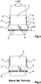
In der
In der Darstellung ist der Winkel zwischen den Befestigungsenden
Gleichzeitig ist erkennbar, dass die beiden Seitenteile
Zur besseren Veranschaulichung ist in der
Schließlich ist in der
Claims (5)
Priority Applications (7)
| Application Number | Priority Date | Filing Date | Title |
|---|---|---|---|
| DE102015114702.5A DE102015114702B4 (en) | 2015-09-03 | 2015-09-03 | holding frame |
| PCT/DE2016/100402 WO2017036465A1 (en) | 2015-09-03 | 2016-09-02 | Holding frame |
| CN201680051301.4A CN107925187A (en) | 2015-09-03 | 2016-09-02 | Keep frame |
| KR1020187008968A KR20180048875A (en) | 2015-09-03 | 2016-09-02 | Phage frame |
| RU2018111329A RU2689157C1 (en) | 2015-09-03 | 2016-09-02 | Retaining frame |
| US15/756,393 US20180277978A1 (en) | 2015-09-03 | 2016-09-02 | Holding frame |
| EP16775071.0A EP3345254A1 (en) | 2015-09-03 | 2016-09-02 | Holding frame |
Applications Claiming Priority (1)
| Application Number | Priority Date | Filing Date | Title |
|---|---|---|---|
| DE102015114702.5A DE102015114702B4 (en) | 2015-09-03 | 2015-09-03 | holding frame |
Publications (2)
| Publication Number | Publication Date |
|---|---|
| DE102015114702A1 DE102015114702A1 (en) | 2017-03-09 |
| DE102015114702B4 true DE102015114702B4 (en) | 2019-01-31 |
Family
ID=57046927
Family Applications (1)
| Application Number | Title | Priority Date | Filing Date |
|---|---|---|---|
| DE102015114702.5A Active DE102015114702B4 (en) | 2015-09-03 | 2015-09-03 | holding frame |
Country Status (7)
| Country | Link |
|---|---|
| US (1) | US20180277978A1 (en) |
| EP (1) | EP3345254A1 (en) |
| KR (1) | KR20180048875A (en) |
| CN (1) | CN107925187A (en) |
| DE (1) | DE102015114702B4 (en) |
| RU (1) | RU2689157C1 (en) |
| WO (1) | WO2017036465A1 (en) |
Families Citing this family (12)
| Publication number | Priority date | Publication date | Assignee | Title |
|---|---|---|---|---|
| DE102015114700B4 (en) | 2015-09-03 | 2020-08-06 | Harting Electric Gmbh & Co. Kg | Holding frame |
| DE102015114699A1 (en) | 2015-09-03 | 2017-03-09 | Harting Electric Gmbh & Co. Kg | Holding frame for connector modules |
| DE102015114703B4 (en) | 2015-09-03 | 2020-03-26 | Harting Electric Gmbh & Co. Kg | Holding frame for connector modules |
| DE102015114701B4 (en) | 2015-09-03 | 2019-01-31 | Harting Electric Gmbh & Co. Kg | Holding frame with blocking element |
| DE102015114697B4 (en) | 2015-09-03 | 2020-03-26 | Harting Electric Gmbh & Co. Kg | Holding frame for connector modules |
| DE102015114696B4 (en) | 2015-09-03 | 2020-10-29 | Harting Electric Gmbh & Co. Kg | Holding frame for connector modules |
| WO2017036439A1 (en) | 2015-09-03 | 2017-03-09 | Harting Electric Gmbh & Co. Kg | Holding frame for plug connector modules |
| DE102016100794B4 (en) * | 2016-01-19 | 2019-03-28 | Harting Electric Gmbh & Co. Kg | Support frame with guide element for connector modules and system consisting of two of these support frames |
| DE102016213251A1 (en) * | 2016-07-20 | 2018-01-25 | Harting Electric Gmbh & Co. Kg | Holding frame arrangement with base frame and fixing element and assembly process |
| DE102016213286A1 (en) | 2016-07-20 | 2018-01-25 | Harting Electric Gmbh & Co. Kg | Multi-part holding frame, assembly and assembly process |
| DE102017129923A1 (en) * | 2017-11-24 | 2019-05-29 | Harting Electric Gmbh & Co. Kg | Grommet |
| CN109244755B (en) * | 2018-10-22 | 2024-01-12 | 浩亭(珠海)制造有限公司 | Connection frame and connector |
Citations (1)
| Publication number | Priority date | Publication date | Assignee | Title |
|---|---|---|---|---|
| DE19707120C1 (en) | 1997-02-22 | 1998-06-25 | Harting Kgaa | Mounting frame for plug-in connector modules |
Family Cites Families (17)
| Publication number | Priority date | Publication date | Assignee | Title |
|---|---|---|---|---|
| US3160280A (en) * | 1963-08-12 | 1964-12-08 | Gen Electric | Device for mounting apparatus |
| US4693440A (en) * | 1986-07-07 | 1987-09-15 | Albert Lalonde | Refreshment cup holder |
| JP3147221B2 (en) * | 1996-02-28 | 2001-03-19 | 矢崎総業株式会社 | Movable connection structure |
| US6692310B2 (en) * | 2001-11-01 | 2004-02-17 | Molex Incorporated | Modular system for stacking electrical connector assemblies |
| DE20217273U1 (en) * | 2002-11-09 | 2003-01-16 | Harting Electric Gmbh & Co Kg | Fastening device for connectors |
| US7141487B2 (en) * | 2004-07-01 | 2006-11-28 | Agency For Science Technology And Research | Method for ultra thinning bumped wafers for flip chip |
| US7056138B2 (en) * | 2004-08-05 | 2006-06-06 | Tellabs Petaluma, Inc. | Retaining clip for Anderson-type power connectors |
| DE202005020026U1 (en) * | 2005-12-22 | 2006-03-16 | Harting Electric Gmbh & Co. Kg | Holding frame for plug-in modules |
| JP4716123B2 (en) * | 2006-06-16 | 2011-07-06 | 住友電装株式会社 | Connector cap holding structure |
| UA29986U (en) * | 2007-04-04 | 2008-02-11 | Общество С Дополнительной Ответственнолстью "Павеж" | Switchboard panel |
| DE102007040496A1 (en) * | 2007-08-21 | 2009-02-26 | Telegärtner Karl Gärtner GmbH | Cable connection device and connection device with such cable processing devices |
| BR112012013831A2 (en) * | 2009-12-09 | 2016-05-03 | Harting Electric Gmbh & Co Kg | system connector |
| DE102012110907B4 (en) * | 2012-11-13 | 2019-06-13 | Harting Electric Gmbh & Co. Kg | Holding frame for holding connector modules |
| US8821186B2 (en) * | 2013-01-14 | 2014-09-02 | Cheng Uei Precision Industry Co., Ltd. | Universal serial bus connector |
| ITMI20130462A1 (en) * | 2013-03-27 | 2014-09-28 | Westec S R L | STRUCTURE OF SUPPORTING FRAME FOR MODULAR CONNECTORS. |
| WO2015149757A2 (en) * | 2014-04-02 | 2015-10-08 | Harting Kgaa | Plug connector system |
| DE102015216929A1 (en) * | 2015-09-03 | 2017-03-09 | Harting Electric Gmbh & Co. Kg | Holding frame for holding connector modules |
-
2015
- 2015-09-03 DE DE102015114702.5A patent/DE102015114702B4/en active Active
-
2016
- 2016-09-02 EP EP16775071.0A patent/EP3345254A1/en not_active Withdrawn
- 2016-09-02 RU RU2018111329A patent/RU2689157C1/en active
- 2016-09-02 WO PCT/DE2016/100402 patent/WO2017036465A1/en active Application Filing
- 2016-09-02 US US15/756,393 patent/US20180277978A1/en not_active Abandoned
- 2016-09-02 KR KR1020187008968A patent/KR20180048875A/en not_active Application Discontinuation
- 2016-09-02 CN CN201680051301.4A patent/CN107925187A/en active Pending
Patent Citations (1)
| Publication number | Priority date | Publication date | Assignee | Title |
|---|---|---|---|---|
| DE19707120C1 (en) | 1997-02-22 | 1998-06-25 | Harting Kgaa | Mounting frame for plug-in connector modules |
Also Published As
| Publication number | Publication date |
|---|---|
| WO2017036465A1 (en) | 2017-03-09 |
| DE102015114702A1 (en) | 2017-03-09 |
| EP3345254A1 (en) | 2018-07-11 |
| KR20180048875A (en) | 2018-05-10 |
| CN107925187A (en) | 2018-04-17 |
| US20180277978A1 (en) | 2018-09-27 |
| RU2689157C1 (en) | 2019-05-24 |
Similar Documents
| Publication | Publication Date | Title |
|---|---|---|
| DE102015114702B4 (en) | holding frame | |
| EP3345260B1 (en) | Retaining frame | |
| DE19707120C1 (en) | Mounting frame for plug-in connector modules | |
| EP3345258B1 (en) | Support frame for connector module | |
| DE102015222561B4 (en) | Holding frame for holding connector modules | |
| DE102015101433B3 (en) | Holding frame for connector modules | |
| EP3178135B1 (en) | Holding frame and method for producing same | |
| EP3345252B1 (en) | Holding frame comprising a fixing element held in a movable manner | |
| EP3014707B2 (en) | Plug connector module | |
| DE202013012813U1 (en) | Connector comprising a protective conductor bridge | |
| DE102014102793B4 (en) | Fastening element for a current sensor | |
| EP2916409A2 (en) | Frame for cable feedthroughs, fastening elements and cable feedthrough system | |
| EP3406002B1 (en) | Holding frame with a guiding element for plug connector modules | |
| DE102016223995A1 (en) | Holding frame for connector modules | |
| EP3108546B1 (en) | System comprising a contact carrier and a corresponding contact carrier | |
| DE202016100789U1 (en) | Control cabinet arrangement with partition | |
| DE102020134152A1 (en) | Switch cabinet arrangement | |
| AT506594B1 (en) | CONNECTOR | |
| DE102015100525A1 (en) | Method for assembling a mullion-transom construction and mullion-transom construction | |
| DE102014001316A1 (en) | connection system | |
| DE202009013725U1 (en) | casing | |
| DE102016110784A1 (en) | Component for a vehicle | |
| DE202006000105U1 (en) | Module link for detachable link of measuring modules has housings in which first link element is arranged and second link element is detachably connectable using sliding connection whereby second link element is connectable by plug link |
Legal Events
| Date | Code | Title | Description |
|---|---|---|---|
| R012 | Request for examination validly filed | ||
| R016 | Response to examination communication | ||
| R018 | Grant decision by examination section/examining division | ||
| R020 | Patent grant now final | ||
| R081 | Change of applicant/patentee |
Owner name: HARTING ELECTRIC STIFTUNG & CO. KG, DE Free format text: FORMER OWNER: HARTING ELECTRIC GMBH & CO. KG, 32339 ESPELKAMP, DE |