EP2024979B1 - Device for absorption of noise - Google Patents
Device for absorption of noise Download PDFInfo
- Publication number
- EP2024979B1 EP2024979B1 EP07725695.6A EP07725695A EP2024979B1 EP 2024979 B1 EP2024979 B1 EP 2024979B1 EP 07725695 A EP07725695 A EP 07725695A EP 2024979 B1 EP2024979 B1 EP 2024979B1
- Authority
- EP
- European Patent Office
- Prior art keywords
- housing
- cable
- face
- fixing
- fixation means
- Prior art date
- Legal status (The legal status is an assumption and is not a legal conclusion. Google has not performed a legal analysis and makes no representation as to the accuracy of the status listed.)
- Active
Links
Images

Classifications
-
- H—ELECTRICITY
- H01—ELECTRIC ELEMENTS
- H01F—MAGNETS; INDUCTANCES; TRANSFORMERS; SELECTION OF MATERIALS FOR THEIR MAGNETIC PROPERTIES
- H01F27/00—Details of transformers or inductances, in general
- H01F27/24—Magnetic cores
- H01F27/26—Fastening parts of the core together; Fastening or mounting the core on casing or support
-
- H—ELECTRICITY
- H01—ELECTRIC ELEMENTS
- H01F—MAGNETS; INDUCTANCES; TRANSFORMERS; SELECTION OF MATERIALS FOR THEIR MAGNETIC PROPERTIES
- H01F27/00—Details of transformers or inductances, in general
- H01F27/33—Arrangements for noise damping
-
- H—ELECTRICITY
- H01—ELECTRIC ELEMENTS
- H01F—MAGNETS; INDUCTANCES; TRANSFORMERS; SELECTION OF MATERIALS FOR THEIR MAGNETIC PROPERTIES
- H01F27/00—Details of transformers or inductances, in general
- H01F27/24—Magnetic cores
- H01F27/26—Fastening parts of the core together; Fastening or mounting the core on casing or support
- H01F27/266—Fastening or mounting the core on casing or support
-
- H—ELECTRICITY
- H03—ELECTRONIC CIRCUITRY
- H03H—IMPEDANCE NETWORKS, e.g. RESONANT CIRCUITS; RESONATORS
- H03H1/00—Constructional details of impedance networks whose electrical mode of operation is not specified or applicable to more than one type of network
-
- H—ELECTRICITY
- H01—ELECTRIC ELEMENTS
- H01F—MAGNETS; INDUCTANCES; TRANSFORMERS; SELECTION OF MATERIALS FOR THEIR MAGNETIC PROPERTIES
- H01F17/00—Fixed inductances of the signal type
- H01F17/04—Fixed inductances of the signal type with magnetic core
- H01F17/06—Fixed inductances of the signal type with magnetic core with core substantially closed in itself, e.g. toroid
- H01F2017/065—Core mounted around conductor to absorb noise, e.g. EMI filter
-
- H—ELECTRICITY
- H01—ELECTRIC ELEMENTS
- H01F—MAGNETS; INDUCTANCES; TRANSFORMERS; SELECTION OF MATERIALS FOR THEIR MAGNETIC PROPERTIES
- H01F27/00—Details of transformers or inductances, in general
- H01F27/02—Casings
- H01F27/027—Casings specially adapted for combination of signal type inductors or transformers with electronic circuits, e.g. mounting on printed circuit boards
Definitions
- the webs are L-shaped in cross section, wherein a leg extends parallel to the end face of the housing and has the fixing edge.
Landscapes
- Engineering & Computer Science (AREA)
- Power Engineering (AREA)
- Shielding Devices Or Components To Electric Or Magnetic Fields (AREA)
- Insertion, Bundling And Securing Of Wires For Electric Apparatuses (AREA)
- Installation Of Indoor Wiring (AREA)
- Details Of Connecting Devices For Male And Female Coupling (AREA)
- Clamps And Clips (AREA)
- Diaphragms For Electromechanical Transducers (AREA)
- Plural Heterocyclic Compounds (AREA)
- Transplanting Machines (AREA)
Description
Die Erfindung betrifft eine Vorrichtung zum Absorbieren des elektrischen Rauschens auf Kabeln.The invention relates to a device for absorbing electrical noise on cables.
Es ist bekannt, dass man die Ausbreitung von elektrischen Störsignalen, auch als Rauschen bezeichnet, auf Kabeln dadurch verhindern kann, dass man das Kabel durch einen entweder vollständig oder fast vollständig geschlossenen Ring aus beispielsweise ferromagnetischem Material hindurch führt. Um dies auch bei vorhandenen Kabeln nachträglich durchführen zu können, sind Vorrichtungen bekannt, bei denen in einem zweischaligen Gehäuse zwei Ringhälften aus ferromagnetischem Material untergebracht sind. Dieses Gehäuse wird um ein Kabel herum geschlossen, so dass sich dann ein geschlossener magnetischer Ring oder ein Ring mit einem kleinen Luftspalt ergibt. Um derartige Vorrichtungen an dem Kabel befestigen zu können, haben die Gehäuse ein Fixiermittel. Dieses Fixiermittel greift an der Isolierung des Kabels an. Es soll verhindern, dass das Gehäuse mit dem ferromagnetischem Material das Kabel entlang rutscht. Beispielsweise ist es bekannt, in einer Öffnung, durch die das Kabel hindurchgeführt ist, Zähne anzuformen, die in das Kabel eingreifen. Bei einer bekannten Vorrichtung dieser Art (
Ebenfalls bekannt ist es (
Weiterhin bekannt ist eine Vorrichtung zum Absorbieren des elektrischen Rauschens auf Kabeln, die ein zweiteiliges Gehäuse mit jeweils einem Ferritelement enthält. An den Stirnseiten des Gehäuses sind an jeder Hälfte mehrere schräg nach außen gerichtete Finger angeformt, die bei geschlossenem Gehäuse mit ihren Enden an dem Kabel anliegen und dadurch das Gehäuse festlegen (Also known is a device for absorbing the electrical noise on cables, which contains a two-part housing, each with a ferrite element. At the end faces of the housing a plurality of obliquely outwardly directed fingers are integrally formed on each half, which rest with the housing closed with their ends to the cable and thereby setting the housing (
Vorrichtungen dieser Art werden häufig an unterschiedlich dicken Kabeln festgelegt. Es gibt aber auch die Problematik, dass die Kabel bei gleicher Dicke unterschiedlich stark flexibel sind. Dies gilt beispielsweise dann, wenn die Kabel dicke massive Drähte aufweisen. In diesem Fall sind sie weniger flexibel als Kabel mit vielen dünnen Litzen.Devices of this type are often fixed to different thickness cables. But there is also the problem that the cables are different degrees of flexibility with the same thickness. This applies, for example, if the cables have thick solid wires. In this case they are less flexible than cables with many thin strands.
Der Erfindung liegt die Aufgabe zu Grunde, eine Vorrichtung zum Absorbieren des elektrischen Rauschens auf Kabeln zu schaffen, die sich an den unterschiedlichsten Arten von Kabeln sicher befestigen lässt.The invention has for its object to provide a device for absorbing electrical noise on cables, which can be securely attached to a variety of types of cables.
Zur Lösung dieser Aufgabe schlägt die Erfindung eine Vorrichtung mit dem im Anspruch 1 genannten Merkmalen vor. Weiterbildungen der Erfindung sind Gegenstand von Unteransprüchen.To solve this problem, the invention proposes a device with the features mentioned in
Die Vorrichtung enthält also ein Gehäuse, in dem das ferromagnetische Material untergebracht ist. Bei dem Gehäuse handelt es sich um ein zweischaliges Gehäuse, ähnlich wie dies im Stand der Technik bekannt ist. Die Verformung der Fixiermittel in Längsrichtung des Kabels macht es möglich, dass bei sehr starren oder auch dicken Kabeln die Fixiermittel ausweichen können, um durch die Verformung ausreichend Reaktionskraft zu entwickeln, die zum Festlegen dient. Je starrer ein Kabel ist, desto mehr Platz steht auch an den Stirnwänden zur Verfügung, da das Kabel dort auch nicht abgeknickt werden kann.The device thus includes a housing in which the ferromagnetic material is housed. The housing is a clam shell similar to that known in the art. The deformation of the fixing means in the longitudinal direction of the cable makes it possible for very rigid or even thick cables, the fixing means can escape to develop enough deformation force by the deformation, which serves for fixing. The more rigid a cable, the more space is also available on the end walls, since the cable can not be bent there.
In Weiterbildung der Erfindung ist vorgesehen, dass das Fixiermittel auch in Querrichtung des Kabels verformbar ausgebildet ist. Hier kann eine zusätzliche Möglichkeit geschaffen werden, unterschiedliche Flexibilitäten und/oder Kabelgrößen auszugleichen.In a further development of the invention it is provided that the fixing means is formed deformable also in the transverse direction of the cable. Here, an additional possibility can be created to compensate for different flexibilities and / or cable sizes.
In Weiterbildung der Erfindung ist vorgesehen, dass das Fixiermittel zwei zwischen sich einen Schlitz bildende Fixierkanten aufweist, zwischen denen das Kabel festlegbar ist. Dies kann entweder so geschehen, dass das Kabel seitlich in den Schlitz hinein gedrückt wird und dadurch festgelegt wird. Wegen der Verformbarkeit in Längsrichtung ist es aber auch möglich, dass das Kabel von der einen Seite her durch das Fixiermittel hindurch geschoben wird, was dann ebenfalls zur Verformung der Fixiermittel führt.In a further development of the invention, it is provided that the fixing means has two fixing edges forming between them, between which the cable can be fixed. This can either be done so that the cable is pressed laterally into the slot and is determined by it. Because of the deformability in the longitudinal direction, it is also possible that the cable is pushed from one side through the fixing means, which then also leads to deformation of the fixing agent.
In Weiterbildung der Erfindung kann vorgesehen sein, dass die Fixierkanten an Stegen ausgebildet sind, die etwa parallel zur Stirnseite des Gehäuses verlaufen. Bei den Stegen kann es sich um flache plattenähnliche Elemente handeln. Diese sind an bestimmten Stellen mit den Stirnseiten des Gehäuses verbunden.In a further development of the invention can be provided that the fixing edges are formed on webs which extend approximately parallel to the end face of the housing. The webs may be flat plate-like elements. These are connected at certain points with the front sides of the housing.
Beispielsweise kann in Weiterbildung der Erfindung vorgesehen sein, dass die Stege im Querschnitt L-förmig sind, wobei ein Schenkel parallel zu der Stirnseite des Gehäuses verläuft und die Fixierkante aufweist.For example, it can be provided in a development of the invention that the webs are L-shaped in cross section, wherein a leg extends parallel to the end face of the housing and has the fixing edge.
Der andere Schenkel ist vorzugsweise einstückig mit der Stirnseite des Gehäuses verbunden.The other leg is preferably integrally connected to the front side of the housing.
Bei einem einseitig offenen Schlitz kann erfindungsgemäß vorgesehen sein, dass die äußeren Enden der Fixierkanten sich in Richtung auf das freie Ende voneinander entfernen.In a slot open on one side, it can be provided according to the invention that the outer ends of the fixing edges move away from one another in the direction of the free end.
An einer geschlossenen Seite des Schlitzes kann vorgesehen sein, dass die Fixierkanten in diesem Bereich parallel zueinander verlaufen.On a closed side of the slot can be provided that the fixing edges in this area are parallel to each other.
Erfindungsgemäß kann vorgesehen sein, dass an beiden gegenüberliegenden Stirnseiten des Gehäuses jeweils ein Fixiermittel vorhanden ist, das vorzugsweise identisch mit dem anderen Fixiermittel ausgebildet ist.According to the invention it can be provided that on both opposite end sides of the housing in each case a fixing means is provided, which is preferably formed identical to the other fixing means.
Weitere Merkmale, Einzelheiten und Vorzüge der Erfindung ergeben sich aus den Ansprüchen, deren Wortlaut durch Bezugnahme zum Inhalt der Beschreibung gemacht wird, der folgenden Beschreibung bevorzugter Ausführungsformen der Erfindung sowie anhand der Zeichnung. Hierbei zeigen:
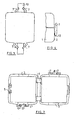
Figur 1- eine Stirnansicht eines geöffneten Gehäuses;
Figur 2- eine Ansicht des geöffneten Gehäuses von der geschlossenen Seite der beiden Gehäuseschalen her;
Figur 3- eine Ansicht des geöffneten Gehäuses von oben in
Figur 1 - Figur 4
- eine Seitenansicht des geschlossenen Gehäuses ohne Kabel;
Figur 5- schematisch eine Draufsicht auf das an einem dicken Kabel festgelegte Gehäuse.
- FIG. 1
- an end view of an open housing;
- FIG. 2
- a view of the open housing from the closed side of the two housing shells ago;
- FIG. 3
- a view of the open housing from the top in
FIG. 1 ; - FIG. 4
- a side view of the closed housing without cable;
- FIG. 5
- schematically a plan view of the fixed to a thick cable housing.
Im Bereich der in
An der zweiten Gehäusehalbschale 1, rechts in
Nun zu
Das Ergebnis der Anbringung eines solchen Gehäuses an einem Kabel 13 ist in
Claims (7)
- A device for absorbing electrical noise on cables (13), comprising1.1 a housing including two half-shells (1) that,1.2 in the closed state, has on each of two end faces (2) an aperture (3) for a cable (13) to be passed through, and comprising1.3 at least one fixation means (6) for fixing the housing on the cable (13), wherein1.4 the fixation means (6) in the vicinity of the aperture (3) engages on the cable (13) on at least one end face (2) of the housing, and1.5 is designed to be deformable in the longitudinal direction and in the transverse direction of the cable (13),characterized in that1.6 a fixation means (6) is arranged on the end face of only one half-shell (1) and, in case of two fixation means (6) present, the second fixation means (6) is arranged on the opposite end face of the housing, and1.7 the fixation means (6) has two fixing edges (9) forming a slot (8) between them and between said fixing edges the cable (13) is fixable.
- The device according to claim 1, wherein the fixing edges (9) are formed on strips (7) which extend roughly parallel to the end face (2) of the housing.
- The device according to claim 2, wherein the strips (7) have L-shaped cross-sections, whereby one leg of the strips (7) extends parallel to the end face (2) of the housing and includes the fixing edge (9).
- The device according to claim 3, wherein the other leg is connected in one piece to the end face (2) of the housing.
- The device according to any one of the preceding claims, wherein the outer ends of the fixing edges (9) diverge away from one another.
- The device according to any one of the preceding claims, wherein the fixing edges (9) extend parallel to one another in the end region of the slot (8).
- The device according to any one of the preceding claims, wherein a fixation means (6) is formed on both end faces (2) of the housing.
Priority Applications (1)
| Application Number | Priority Date | Filing Date | Title |
|---|---|---|---|
| PL07725695T PL2024979T3 (en) | 2006-06-08 | 2007-05-31 | Device for absorption of noise |
Applications Claiming Priority (2)
| Application Number | Priority Date | Filing Date | Title |
|---|---|---|---|
| DE102006027312A DE102006027312A1 (en) | 2006-06-08 | 2006-06-08 | Device for absorbing the noise |
| PCT/EP2007/004808 WO2007140918A1 (en) | 2006-06-08 | 2007-05-31 | Device for absorption of noise |
Publications (2)
| Publication Number | Publication Date |
|---|---|
| EP2024979A1 EP2024979A1 (en) | 2009-02-18 |
| EP2024979B1 true EP2024979B1 (en) | 2014-12-31 |
Family
ID=38375697
Family Applications (1)
| Application Number | Title | Priority Date | Filing Date |
|---|---|---|---|
| EP07725695.6A Active EP2024979B1 (en) | 2006-06-08 | 2007-05-31 | Device for absorption of noise |
Country Status (19)
| Country | Link |
|---|---|
| US (1) | US8263868B2 (en) |
| EP (1) | EP2024979B1 (en) |
| JP (1) | JP5438508B2 (en) |
| KR (1) | KR101379572B1 (en) |
| CN (1) | CN101467223B (en) |
| AU (1) | AU2007256433B2 (en) |
| BR (1) | BRPI0711958B1 (en) |
| CA (1) | CA2653229C (en) |
| DE (1) | DE102006027312A1 (en) |
| DK (1) | DK2024979T3 (en) |
| ES (1) | ES2531172T3 (en) |
| IL (1) | IL195728A (en) |
| MX (1) | MX2008015566A (en) |
| NO (1) | NO339161B1 (en) |
| PL (1) | PL2024979T3 (en) |
| PT (1) | PT2024979E (en) |
| RU (1) | RU2438202C2 (en) |
| TW (1) | TWI409030B (en) |
| WO (1) | WO2007140918A1 (en) |
Families Citing this family (7)
| Publication number | Priority date | Publication date | Assignee | Title |
|---|---|---|---|---|
| DE102010034517B4 (en) | 2009-08-17 | 2022-10-06 | Sew-Eurodrive Gmbh & Co Kg | Hybrid connector and converter motor with the hybrid connector |
| TWD145807S1 (en) | 2010-10-26 | 2012-03-11 | 伍斯艾索斯電子公司 | Electronic component |
| TWD145806S1 (en) | 2010-10-26 | 2012-03-11 | 伍斯艾索斯電子公司 | Electronic component |
| DE102015205193A1 (en) * | 2015-03-23 | 2016-09-29 | Würth Elektronik eiSos Gmbh & Co. KG | Device for absorbing electrical noise |
| JP2017004886A (en) * | 2015-06-15 | 2017-01-05 | 住友電装株式会社 | Protector and wire harness |
| DE102019215619B3 (en) * | 2019-10-11 | 2020-12-24 | Würth Elektronik eiSos Gmbh & Co. KG | Apparatus for absorbing electrical noise on conduits and methods of placing such apparatus |
| CN113571290A (en) * | 2021-07-20 | 2021-10-29 | 华翔翔能科技股份有限公司 | Low-noise transformer |
Family Cites Families (26)
| Publication number | Priority date | Publication date | Assignee | Title |
|---|---|---|---|---|
| US3183302A (en) * | 1962-01-08 | 1965-05-11 | Jasper Blackburn Corp | Cover for an electrical connector |
| US3278674A (en) * | 1964-06-12 | 1966-10-11 | Burndy Corp | Connector insulating housing |
| US3462715A (en) | 1966-06-06 | 1969-08-19 | Itt | Removable electrical connector filter assembly |
| US3484541A (en) | 1968-09-27 | 1969-12-16 | Anderson Electric Corp | Electrical connector cover |
| DE3300779C2 (en) * | 1983-01-12 | 1984-12-06 | Fa. A. Raymond, 7850 Lörrach | Cable clamp for variable diameters |
| US4644610A (en) * | 1984-09-06 | 1987-02-24 | Fish Ivan L | Disc shaped holder with an expandable center hole |
| JPH0234875Y2 (en) | 1986-08-29 | 1990-09-19 | ||
| SU1550087A1 (en) | 1988-05-18 | 1990-03-15 | Предприятие П/Я М-5478 | Pull-off device for running deep-well equipment into hole |
| US5374017A (en) * | 1989-02-17 | 1994-12-20 | Martin; William B. | Cable fitting |
| US5003278A (en) * | 1990-03-01 | 1991-03-26 | Ferrishield, Inc. | Ferrite suppressor case with retaining fingers |
| JPH03268397A (en) * | 1990-03-17 | 1991-11-29 | Tdk Corp | Noise-absorbing apparatus |
| DE19536155A1 (en) * | 1995-09-29 | 1997-04-03 | Wuerth Elektronik Gmbh & Co Kg | Device for absorbing electrical noise |
| US5900796A (en) * | 1997-02-26 | 1999-05-04 | Fair-Rite Products Corporation | Electric noise suppressor |
| JP2000515677A (en) | 1997-05-22 | 2000-11-21 | トーマス アンド ベッツ インターナショナル,インク. | Cable splice closure |
| DE19811048A1 (en) * | 1998-03-13 | 1999-09-23 | Wuerth Elektronik Gmbh & Co Kg | Absorber of electric noise |
| US6335672B1 (en) * | 1998-12-23 | 2002-01-01 | L.L. Culmat Lp | Holder for ferrite noise suppressor |
| DE19912917A1 (en) * | 1999-03-22 | 2000-09-28 | Wuerth Elektronik Gmbh & Co Kg | Electrical noise absorber and method for mounting it on a cable |
| US6335748B1 (en) * | 1999-05-06 | 2002-01-01 | Xerox Corporation | On-line image-on-image color registration control systems and methods based on time-scheduled control loop switching |
| CN1182442C (en) * | 1999-10-15 | 2004-12-29 | 株式会社理光 | Photoreceptor assembly and image forming device |
| DE10010452A1 (en) * | 1999-12-02 | 2001-06-07 | Rxs Kabelgarnituren Gmbh & Co | Sealing body for longitudinally divided cable fittings |
| CN1311600C (en) | 1999-12-02 | 2007-04-18 | Ccs技术公司 | Seals for longitudinally split cable fittings |
| US7044761B2 (en) * | 2003-04-10 | 2006-05-16 | Panduit Corp. | Transparent insulating enclosure |
| DE10326685A1 (en) * | 2003-06-03 | 2004-12-23 | Würth Elektronik eiSos Gmbh & Co. KG | Device for absorbing the noise |
| JP4077816B2 (en) * | 2004-07-07 | 2008-04-23 | Tdk株式会社 | Noise absorber |
| US7094972B2 (en) * | 2004-07-13 | 2006-08-22 | Thomas & Betts International, Inc. | Insulating cover for electrical connectors |
| KR100601511B1 (en) * | 2004-09-24 | 2006-07-19 | 삼성에스디아이 주식회사 | Lithium Polymer Battery and Manufacturing Method Thereof |
-
2006
- 2006-06-08 DE DE102006027312A patent/DE102006027312A1/en not_active Ceased
-
2007
- 2007-05-31 PL PL07725695T patent/PL2024979T3/en unknown
- 2007-05-31 PT PT07725695T patent/PT2024979E/en unknown
- 2007-05-31 EP EP07725695.6A patent/EP2024979B1/en active Active
- 2007-05-31 MX MX2008015566A patent/MX2008015566A/en active IP Right Grant
- 2007-05-31 JP JP2009513579A patent/JP5438508B2/en active Active
- 2007-05-31 AU AU2007256433A patent/AU2007256433B2/en active Active
- 2007-05-31 WO PCT/EP2007/004808 patent/WO2007140918A1/en not_active Ceased
- 2007-05-31 BR BRPI0711958-5A patent/BRPI0711958B1/en active IP Right Grant
- 2007-05-31 ES ES07725695T patent/ES2531172T3/en active Active
- 2007-05-31 CA CA2653229A patent/CA2653229C/en active Active
- 2007-05-31 RU RU2008146848/07A patent/RU2438202C2/en active
- 2007-05-31 CN CN200780021163.6A patent/CN101467223B/en active Active
- 2007-05-31 KR KR1020087029235A patent/KR101379572B1/en active Active
- 2007-05-31 US US12/303,593 patent/US8263868B2/en active Active
- 2007-05-31 DK DK07725695T patent/DK2024979T3/en active
- 2007-06-08 TW TW096120806A patent/TWI409030B/en active
-
2008
- 2008-12-04 IL IL195728A patent/IL195728A/en active IP Right Grant
- 2008-12-08 NO NO20085111A patent/NO339161B1/en unknown
Also Published As
| Publication number | Publication date |
|---|---|
| WO2007140918A1 (en) | 2007-12-13 |
| CN101467223A (en) | 2009-06-24 |
| US8263868B2 (en) | 2012-09-11 |
| RU2438202C2 (en) | 2011-12-27 |
| IL195728A (en) | 2014-09-30 |
| NO339161B1 (en) | 2016-11-14 |
| JP2009540552A (en) | 2009-11-19 |
| AU2007256433A1 (en) | 2007-12-13 |
| DK2024979T3 (en) | 2015-04-13 |
| IL195728A0 (en) | 2009-09-01 |
| KR20090021342A (en) | 2009-03-03 |
| TW200808166A (en) | 2008-02-01 |
| NO20085111L (en) | 2009-02-16 |
| KR101379572B1 (en) | 2014-03-31 |
| CA2653229A1 (en) | 2007-12-13 |
| MX2008015566A (en) | 2009-02-23 |
| PL2024979T3 (en) | 2015-05-29 |
| AU2007256433B2 (en) | 2011-12-22 |
| CN101467223B (en) | 2014-10-08 |
| HK1125738A1 (en) | 2009-08-14 |
| RU2008146848A (en) | 2010-07-20 |
| JP5438508B2 (en) | 2014-03-12 |
| ES2531172T3 (en) | 2015-03-11 |
| CA2653229C (en) | 2015-04-07 |
| EP2024979A1 (en) | 2009-02-18 |
| US20100170712A1 (en) | 2010-07-08 |
| DE102006027312A1 (en) | 2007-12-13 |
| TWI409030B (en) | 2013-09-11 |
| BRPI0711958B1 (en) | 2018-06-05 |
| PT2024979E (en) | 2015-03-24 |
| BRPI0711958A2 (en) | 2011-12-20 |
Similar Documents
| Publication | Publication Date | Title |
|---|---|---|
| EP2024979B1 (en) | Device for absorption of noise | |
| EP2106006B1 (en) | Cable feedthrough | |
| DE102008028278B4 (en) | Device for passing and holding cables or other strands | |
| EP3714520B1 (en) | Cable feedthrough | |
| EP3439925A1 (en) | Buckle tongue with a deflecting element | |
| DE102015100257A1 (en) | Conductor terminal for clamping at least one electrical conductor | |
| DE10253858B4 (en) | Terminal clamping element and thus formed terminal | |
| DE102020204526A1 (en) | Device for the implementation and strain relief of strands | |
| EP1039632B1 (en) | Electric noise absorber and method of connection to a cable | |
| DE19901914A1 (en) | Holding device for cables routed through walls | |
| DE19536155A1 (en) | Device for absorbing electrical noise | |
| EP3038213B1 (en) | Cable connection terminal for clamping at least one electrical conductor | |
| EP1632042B1 (en) | Device for absorbing noise | |
| EP3522307A1 (en) | Cable strain relief and shield fixing in a connector housing | |
| DE10333499A1 (en) | Cable entry plate | |
| DE202010004995U1 (en) | Fastener for fastening a first component to a second component | |
| EP3120456B1 (en) | Apparatus for absorbing electrical noise on cables | |
| DE19908455A1 (en) | Cable clamp for mechanical holding and electrical connection of a cable | |
| DE202007015787U1 (en) | holder | |
| DE112014002199B4 (en) | Electronic assembly with a plastic housing | |
| DE102024110585A1 (en) | Locking element, connector and electrical plug connection formed thereby | |
| DE102010039203A1 (en) | Receptacle element for use in circuit board for connecting duct elements, has contact guide for pressurizing inserted wire end transverse to plug-in direction and pressing inserted wire end against wall of receiving space | |
| DE102009024913B4 (en) | Connection terminal for electrical wiring and manufacturing method for metal components for this connection idemme | |
| DE112018007584T5 (en) | Terminal block assembly | |
| DE102010018596B4 (en) | Cable entry |
Legal Events
| Date | Code | Title | Description |
|---|---|---|---|
| PUAI | Public reference made under article 153(3) epc to a published international application that has entered the european phase |
Free format text: ORIGINAL CODE: 0009012 |
|
| 17P | Request for examination filed |
Effective date: 20081110 |
|
| AK | Designated contracting states |
Kind code of ref document: A1 Designated state(s): AT BE BG CH CY CZ DE DK EE ES FI FR GB GR HU IE IS IT LI LT LU LV MC MT NL PL PT RO SE SI SK TR |
|
| AX | Request for extension of the european patent |
Extension state: AL BA HR MK RS |
|
| REG | Reference to a national code |
Ref country code: HK Ref legal event code: DE Ref document number: 1125738 Country of ref document: HK |
|
| DAX | Request for extension of the european patent (deleted) | ||
| 17Q | First examination report despatched |
Effective date: 20121113 |
|
| GRAP | Despatch of communication of intention to grant a patent |
Free format text: ORIGINAL CODE: EPIDOSNIGR1 |
|
| INTG | Intention to grant announced |
Effective date: 20140922 |
|
| GRAS | Grant fee paid |
Free format text: ORIGINAL CODE: EPIDOSNIGR3 |
|
| GRAA | (expected) grant |
Free format text: ORIGINAL CODE: 0009210 |
|
| AK | Designated contracting states |
Kind code of ref document: B1 Designated state(s): AT BE BG CH CY CZ DE DK EE ES FI FR GB GR HU IE IS IT LI LT LU LV MC MT NL PL PT RO SE SI SK TR |
|
| RAP1 | Party data changed (applicant data changed or rights of an application transferred) |
Owner name: WUERTH ELEKTRONIK EISOS GMBH & CO. KG |
|
| REG | Reference to a national code |
Ref country code: GB Ref legal event code: FG4D Free format text: NOT ENGLISH Ref country code: CH Ref legal event code: EP |
|
| REG | Reference to a national code |
Ref country code: CH Ref legal event code: NV Representative=s name: DR. LUSUARDI AG, CH |
|
| REG | Reference to a national code |
Ref country code: IE Ref legal event code: FG4D Free format text: LANGUAGE OF EP DOCUMENT: GERMAN |
|
| REG | Reference to a national code |
Ref country code: AT Ref legal event code: REF Ref document number: 704824 Country of ref document: AT Kind code of ref document: T Effective date: 20150215 |
|
| REG | Reference to a national code |
Ref country code: DE Ref legal event code: R096 Ref document number: 502007013656 Country of ref document: DE Effective date: 20150219 |
|
| REG | Reference to a national code |
Ref country code: SE Ref legal event code: TRGR |
|
| REG | Reference to a national code |
Ref country code: ES Ref legal event code: FG2A Ref document number: 2531172 Country of ref document: ES Kind code of ref document: T3 Effective date: 20150311 |
|
| REG | Reference to a national code |
Ref country code: PT Ref legal event code: SC4A Free format text: AVAILABILITY OF NATIONAL TRANSLATION Effective date: 20150311 |
|
| REG | Reference to a national code |
Ref country code: NL Ref legal event code: T3 |
|
| REG | Reference to a national code |
Ref country code: DK Ref legal event code: T3 Effective date: 20150409 |
|
| REG | Reference to a national code |
Ref country code: GR Ref legal event code: EP Ref document number: 20150400377 Country of ref document: GR Effective date: 20150318 |
|
| PG25 | Lapsed in a contracting state [announced via postgrant information from national office to epo] |
Ref country code: LT Free format text: LAPSE BECAUSE OF FAILURE TO SUBMIT A TRANSLATION OF THE DESCRIPTION OR TO PAY THE FEE WITHIN THE PRESCRIBED TIME-LIMIT Effective date: 20141231 |
|
| REG | Reference to a national code |
Ref country code: LT Ref legal event code: MG4D |
|
| PG25 | Lapsed in a contracting state [announced via postgrant information from national office to epo] |
Ref country code: LV Free format text: LAPSE BECAUSE OF FAILURE TO SUBMIT A TRANSLATION OF THE DESCRIPTION OR TO PAY THE FEE WITHIN THE PRESCRIBED TIME-LIMIT Effective date: 20141231 |
|
| REG | Reference to a national code |
Ref country code: PL Ref legal event code: T3 |
|
| REG | Reference to a national code |
Ref country code: HK Ref legal event code: GR Ref document number: 1125738 Country of ref document: HK |
|
| PG25 | Lapsed in a contracting state [announced via postgrant information from national office to epo] |
Ref country code: RO Free format text: LAPSE BECAUSE OF FAILURE TO SUBMIT A TRANSLATION OF THE DESCRIPTION OR TO PAY THE FEE WITHIN THE PRESCRIBED TIME-LIMIT Effective date: 20141231 Ref country code: CZ Free format text: LAPSE BECAUSE OF FAILURE TO SUBMIT A TRANSLATION OF THE DESCRIPTION OR TO PAY THE FEE WITHIN THE PRESCRIBED TIME-LIMIT Effective date: 20141231 Ref country code: SK Free format text: LAPSE BECAUSE OF FAILURE TO SUBMIT A TRANSLATION OF THE DESCRIPTION OR TO PAY THE FEE WITHIN THE PRESCRIBED TIME-LIMIT Effective date: 20141231 |
|
| PG25 | Lapsed in a contracting state [announced via postgrant information from national office to epo] |
Ref country code: IS Free format text: LAPSE BECAUSE OF FAILURE TO SUBMIT A TRANSLATION OF THE DESCRIPTION OR TO PAY THE FEE WITHIN THE PRESCRIBED TIME-LIMIT Effective date: 20150430 |
|
| REG | Reference to a national code |
Ref country code: DE Ref legal event code: R097 Ref document number: 502007013656 Country of ref document: DE |
|
| PG25 | Lapsed in a contracting state [announced via postgrant information from national office to epo] |
Ref country code: EE Free format text: LAPSE BECAUSE OF FAILURE TO SUBMIT A TRANSLATION OF THE DESCRIPTION OR TO PAY THE FEE WITHIN THE PRESCRIBED TIME-LIMIT Effective date: 20141231 |
|
| PLBE | No opposition filed within time limit |
Free format text: ORIGINAL CODE: 0009261 |
|
| STAA | Information on the status of an ep patent application or granted ep patent |
Free format text: STATUS: NO OPPOSITION FILED WITHIN TIME LIMIT |
|
| REG | Reference to a national code |
Ref country code: HU Ref legal event code: AG4A Ref document number: E024522 Country of ref document: HU |
|
| 26N | No opposition filed |
Effective date: 20151001 |
|
| PG25 | Lapsed in a contracting state [announced via postgrant information from national office to epo] |
Ref country code: MC Free format text: LAPSE BECAUSE OF FAILURE TO SUBMIT A TRANSLATION OF THE DESCRIPTION OR TO PAY THE FEE WITHIN THE PRESCRIBED TIME-LIMIT Effective date: 20141231 Ref country code: LU Free format text: LAPSE BECAUSE OF FAILURE TO SUBMIT A TRANSLATION OF THE DESCRIPTION OR TO PAY THE FEE WITHIN THE PRESCRIBED TIME-LIMIT Effective date: 20150531 |
|
| PG25 | Lapsed in a contracting state [announced via postgrant information from national office to epo] |
Ref country code: SI Free format text: LAPSE BECAUSE OF FAILURE TO SUBMIT A TRANSLATION OF THE DESCRIPTION OR TO PAY THE FEE WITHIN THE PRESCRIBED TIME-LIMIT Effective date: 20141231 |
|
| REG | Reference to a national code |
Ref country code: FR Ref legal event code: PLFP Year of fee payment: 10 |
|
| PG25 | Lapsed in a contracting state [announced via postgrant information from national office to epo] |
Ref country code: MT Free format text: LAPSE BECAUSE OF FAILURE TO SUBMIT A TRANSLATION OF THE DESCRIPTION OR TO PAY THE FEE WITHIN THE PRESCRIBED TIME-LIMIT Effective date: 20141231 |
|
| REG | Reference to a national code |
Ref country code: FR Ref legal event code: PLFP Year of fee payment: 11 |
|
| PG25 | Lapsed in a contracting state [announced via postgrant information from national office to epo] |
Ref country code: CY Free format text: LAPSE BECAUSE OF FAILURE TO SUBMIT A TRANSLATION OF THE DESCRIPTION OR TO PAY THE FEE WITHIN THE PRESCRIBED TIME-LIMIT Effective date: 20141231 |
|
| REG | Reference to a national code |
Ref country code: FR Ref legal event code: PLFP Year of fee payment: 12 |
|
| P01 | Opt-out of the competence of the unified patent court (upc) registered |
Effective date: 20230525 |
|
| PGFP | Annual fee paid to national office [announced via postgrant information from national office to epo] |
Ref country code: NL Payment date: 20250521 Year of fee payment: 19 |
|
| PGFP | Annual fee paid to national office [announced via postgrant information from national office to epo] |
Ref country code: FI Payment date: 20250526 Year of fee payment: 19 |
|
| PGFP | Annual fee paid to national office [announced via postgrant information from national office to epo] |
Ref country code: PL Payment date: 20250522 Year of fee payment: 19 Ref country code: DE Payment date: 20250521 Year of fee payment: 19 |
|
| PGFP | Annual fee paid to national office [announced via postgrant information from national office to epo] |
Ref country code: GB Payment date: 20250521 Year of fee payment: 19 Ref country code: DK Payment date: 20250526 Year of fee payment: 19 Ref country code: ES Payment date: 20250627 Year of fee payment: 19 |
|
| PGFP | Annual fee paid to national office [announced via postgrant information from national office to epo] |
Ref country code: HU Payment date: 20250523 Year of fee payment: 19 |
|
| PGFP | Annual fee paid to national office [announced via postgrant information from national office to epo] |
Ref country code: BE Payment date: 20250521 Year of fee payment: 19 Ref country code: IT Payment date: 20250527 Year of fee payment: 19 |
|
| PGFP | Annual fee paid to national office [announced via postgrant information from national office to epo] |
Ref country code: PT Payment date: 20250522 Year of fee payment: 19 |
|
| PGFP | Annual fee paid to national office [announced via postgrant information from national office to epo] |
Ref country code: FR Payment date: 20250528 Year of fee payment: 19 |
|
| PGFP | Annual fee paid to national office [announced via postgrant information from national office to epo] |
Ref country code: BG Payment date: 20250521 Year of fee payment: 19 Ref country code: GR Payment date: 20250523 Year of fee payment: 19 |
|
| PGFP | Annual fee paid to national office [announced via postgrant information from national office to epo] |
Ref country code: CH Payment date: 20250601 Year of fee payment: 19 |
|
| PGFP | Annual fee paid to national office [announced via postgrant information from national office to epo] |
Ref country code: AT Payment date: 20250522 Year of fee payment: 19 |
|
| PGFP | Annual fee paid to national office [announced via postgrant information from national office to epo] |
Ref country code: TR Payment date: 20250526 Year of fee payment: 19 |
|
| PGFP | Annual fee paid to national office [announced via postgrant information from national office to epo] |
Ref country code: IE Payment date: 20250521 Year of fee payment: 19 |
|
| PGFP | Annual fee paid to national office [announced via postgrant information from national office to epo] |
Ref country code: SE Payment date: 20250521 Year of fee payment: 19 |