EP1236236B1 - Fuel cell assembly - Google Patents
Fuel cell assembly Download PDFInfo
- Publication number
- EP1236236B1 EP1236236B1 EP00967438A EP00967438A EP1236236B1 EP 1236236 B1 EP1236236 B1 EP 1236236B1 EP 00967438 A EP00967438 A EP 00967438A EP 00967438 A EP00967438 A EP 00967438A EP 1236236 B1 EP1236236 B1 EP 1236236B1
- Authority
- EP
- European Patent Office
- Prior art keywords
- assembly according
- layer
- tubular
- cathode
- anode
- Prior art date
- Legal status (The legal status is an assumption and is not a legal conclusion. Google has not performed a legal analysis and makes no representation as to the accuracy of the status listed.)
- Expired - Lifetime
Links
- 239000000446 fuel Substances 0.000 title claims abstract description 92
- 239000003792 electrolyte Substances 0.000 claims abstract description 31
- 229910052759 nickel Inorganic materials 0.000 claims abstract description 28
- 239000007787 solid Substances 0.000 claims abstract description 19
- 239000002737 fuel gas Substances 0.000 claims abstract description 16
- 229910000990 Ni alloy Inorganic materials 0.000 claims abstract description 15
- 239000010410 layer Substances 0.000 claims description 137
- PXHVJJICTQNCMI-UHFFFAOYSA-N nickel Substances [Ni] PXHVJJICTQNCMI-UHFFFAOYSA-N 0.000 claims description 78
- 238000000429 assembly Methods 0.000 claims description 30
- 230000000712 assembly Effects 0.000 claims description 30
- 239000000463 material Substances 0.000 claims description 26
- 229910052709 silver Inorganic materials 0.000 claims description 19
- 239000004332 silver Substances 0.000 claims description 19
- 239000011195 cermet Substances 0.000 claims description 17
- 239000007789 gas Substances 0.000 claims description 13
- 239000001301 oxygen Substances 0.000 claims description 12
- 229910052760 oxygen Inorganic materials 0.000 claims description 12
- QVGXLLKOCUKJST-UHFFFAOYSA-N atomic oxygen Chemical compound [O] QVGXLLKOCUKJST-UHFFFAOYSA-N 0.000 claims description 11
- 230000015572 biosynthetic process Effects 0.000 claims description 7
- 238000005755 formation reaction Methods 0.000 claims description 7
- 239000000956 alloy Substances 0.000 claims description 6
- 229910000510 noble metal Inorganic materials 0.000 claims description 6
- 239000000758 substrate Substances 0.000 claims description 6
- 229910000831 Steel Inorganic materials 0.000 claims description 5
- 229910045601 alloy Inorganic materials 0.000 claims description 5
- 239000004020 conductor Substances 0.000 claims description 5
- 239000010959 steel Substances 0.000 claims description 5
- 238000005245 sintering Methods 0.000 claims description 4
- 229910052751 metal Inorganic materials 0.000 claims description 3
- 239000002184 metal Substances 0.000 claims description 3
- 239000002344 surface layer Substances 0.000 claims description 3
- 239000011888 foil Substances 0.000 claims description 2
- BQCADISMDOOEFD-UHFFFAOYSA-N Silver Chemical compound [Ag] BQCADISMDOOEFD-UHFFFAOYSA-N 0.000 description 18
- 238000001125 extrusion Methods 0.000 description 17
- MCMNRKCIXSYSNV-UHFFFAOYSA-N Zirconium dioxide Chemical compound O=[Zr]=O MCMNRKCIXSYSNV-UHFFFAOYSA-N 0.000 description 12
- 239000000843 powder Substances 0.000 description 12
- PEDCQBHIVMGVHV-UHFFFAOYSA-N Glycerine Chemical compound OCC(O)CO PEDCQBHIVMGVHV-UHFFFAOYSA-N 0.000 description 9
- 239000011230 binding agent Substances 0.000 description 9
- 238000000034 method Methods 0.000 description 8
- 239000004014 plasticizer Substances 0.000 description 8
- 238000007581 slurry coating method Methods 0.000 description 8
- XLYOFNOQVPJJNP-UHFFFAOYSA-N water Substances O XLYOFNOQVPJJNP-UHFFFAOYSA-N 0.000 description 8
- 239000002904 solvent Substances 0.000 description 7
- VNWKTOKETHGBQD-UHFFFAOYSA-N methane Chemical compound C VNWKTOKETHGBQD-UHFFFAOYSA-N 0.000 description 6
- BQENXCOZCUHKRE-UHFFFAOYSA-N [La+3].[La+3].[O-][Mn]([O-])=O.[O-][Mn]([O-])=O.[O-][Mn]([O-])=O Chemical compound [La+3].[La+3].[O-][Mn]([O-])=O.[O-][Mn]([O-])=O.[O-][Mn]([O-])=O BQENXCOZCUHKRE-UHFFFAOYSA-N 0.000 description 5
- 230000035939 shock Effects 0.000 description 5
- 229910052712 strontium Inorganic materials 0.000 description 5
- CIOAGBVUUVVLOB-UHFFFAOYSA-N strontium atom Chemical compound [Sr] CIOAGBVUUVVLOB-UHFFFAOYSA-N 0.000 description 5
- 239000004372 Polyvinyl alcohol Substances 0.000 description 4
- 239000000203 mixture Substances 0.000 description 4
- 229920002451 polyvinyl alcohol Polymers 0.000 description 4
- 230000002787 reinforcement Effects 0.000 description 4
- ZWEHNKRNPOVVGH-UHFFFAOYSA-N 2-Butanone Chemical compound CCC(C)=O ZWEHNKRNPOVVGH-UHFFFAOYSA-N 0.000 description 3
- YXFVVABEGXRONW-UHFFFAOYSA-N Toluene Chemical compound CC1=CC=CC=C1 YXFVVABEGXRONW-UHFFFAOYSA-N 0.000 description 3
- 239000011248 coating agent Substances 0.000 description 3
- 238000000576 coating method Methods 0.000 description 3
- 229910002080 8 mol% Y2O3 fully stabilized ZrO2 Inorganic materials 0.000 description 2
- RYGMFSIKBFXOCR-UHFFFAOYSA-N Copper Chemical compound [Cu] RYGMFSIKBFXOCR-UHFFFAOYSA-N 0.000 description 2
- 238000005266 casting Methods 0.000 description 2
- 239000000919 ceramic Substances 0.000 description 2
- 229910010293 ceramic material Inorganic materials 0.000 description 2
- 229910052802 copper Inorganic materials 0.000 description 2
- 239000010949 copper Substances 0.000 description 2
- 238000001035 drying Methods 0.000 description 2
- 238000009472 formulation Methods 0.000 description 2
- 238000010438 heat treatment Methods 0.000 description 2
- 239000001257 hydrogen Substances 0.000 description 2
- 229910052739 hydrogen Inorganic materials 0.000 description 2
- 239000007769 metal material Substances 0.000 description 2
- 238000012986 modification Methods 0.000 description 2
- 230000004048 modification Effects 0.000 description 2
- 239000003960 organic solvent Substances 0.000 description 2
- 239000007800 oxidant agent Substances 0.000 description 2
- 230000001590 oxidative effect Effects 0.000 description 2
- BASFCYQUMIYNBI-UHFFFAOYSA-N platinum Chemical compound [Pt] BASFCYQUMIYNBI-UHFFFAOYSA-N 0.000 description 2
- 238000010248 power generation Methods 0.000 description 2
- 238000002407 reforming Methods 0.000 description 2
- 238000000518 rheometry Methods 0.000 description 2
- 238000007650 screen-printing Methods 0.000 description 2
- 238000005507 spraying Methods 0.000 description 2
- 229910000975 Carbon steel Inorganic materials 0.000 description 1
- UFHFLCQGNIYNRP-UHFFFAOYSA-N Hydrogen Chemical compound [H][H] UFHFLCQGNIYNRP-UHFFFAOYSA-N 0.000 description 1
- 238000005275 alloying Methods 0.000 description 1
- PNEYBMLMFCGWSK-UHFFFAOYSA-N aluminium oxide Inorganic materials [O-2].[O-2].[O-2].[Al+3].[Al+3] PNEYBMLMFCGWSK-UHFFFAOYSA-N 0.000 description 1
- 239000010405 anode material Substances 0.000 description 1
- 239000003054 catalyst Substances 0.000 description 1
- 239000010406 cathode material Substances 0.000 description 1
- 238000006243 chemical reaction Methods 0.000 description 1
- 239000003245 coal Substances 0.000 description 1
- 238000010276 construction Methods 0.000 description 1
- 238000011109 contamination Methods 0.000 description 1
- 230000001351 cycling effect Effects 0.000 description 1
- 230000001627 detrimental effect Effects 0.000 description 1
- 238000010410 dusting Methods 0.000 description 1
- 230000005611 electricity Effects 0.000 description 1
- 239000002001 electrolyte material Substances 0.000 description 1
- 239000011532 electronic conductor Substances 0.000 description 1
- 230000007717 exclusion Effects 0.000 description 1
- 150000002431 hydrogen Chemical class 0.000 description 1
- 239000010416 ion conductor Substances 0.000 description 1
- 239000012528 membrane Substances 0.000 description 1
- 238000002156 mixing Methods 0.000 description 1
- 239000003345 natural gas Substances 0.000 description 1
- 150000002815 nickel Chemical class 0.000 description 1
- -1 oxygen ions Chemical class 0.000 description 1
- 239000002245 particle Substances 0.000 description 1
- 229910052697 platinum Inorganic materials 0.000 description 1
- 231100000572 poisoning Toxicity 0.000 description 1
- 230000000607 poisoning effect Effects 0.000 description 1
- 238000005096 rolling process Methods 0.000 description 1
- 239000003566 sealing material Substances 0.000 description 1
- 150000003378 silver Chemical class 0.000 description 1
- 239000002002 slurry Substances 0.000 description 1
- 238000005476 soldering Methods 0.000 description 1
- 238000004528 spin coating Methods 0.000 description 1
- 238000000629 steam reforming Methods 0.000 description 1
- 239000002470 thermal conductor Substances 0.000 description 1
- 238000005382 thermal cycling Methods 0.000 description 1
- 229920002554 vinyl polymer Polymers 0.000 description 1
- 238000003466 welding Methods 0.000 description 1
- 238000004804 winding Methods 0.000 description 1
Images

Classifications
-
- H—ELECTRICITY
- H01—ELECTRIC ELEMENTS
- H01M—PROCESSES OR MEANS, e.g. BATTERIES, FOR THE DIRECT CONVERSION OF CHEMICAL ENERGY INTO ELECTRICAL ENERGY
- H01M8/00—Fuel cells; Manufacture thereof
- H01M8/24—Grouping of fuel cells, e.g. stacking of fuel cells
- H01M8/241—Grouping of fuel cells, e.g. stacking of fuel cells with solid or matrix-supported electrolytes
- H01M8/2425—High-temperature cells with solid electrolytes
- H01M8/2435—High-temperature cells with solid electrolytes with monolithic core structure, e.g. honeycombs
-
- H—ELECTRICITY
- H01—ELECTRIC ELEMENTS
- H01M—PROCESSES OR MEANS, e.g. BATTERIES, FOR THE DIRECT CONVERSION OF CHEMICAL ENERGY INTO ELECTRICAL ENERGY
- H01M8/00—Fuel cells; Manufacture thereof
- H01M8/02—Details
- H01M8/0202—Collectors; Separators, e.g. bipolar separators; Interconnectors
- H01M8/023—Porous and characterised by the material
- H01M8/0232—Metals or alloys
-
- H—ELECTRICITY
- H01—ELECTRIC ELEMENTS
- H01M—PROCESSES OR MEANS, e.g. BATTERIES, FOR THE DIRECT CONVERSION OF CHEMICAL ENERGY INTO ELECTRICAL ENERGY
- H01M4/00—Electrodes
- H01M4/86—Inert electrodes with catalytic activity, e.g. for fuel cells
- H01M4/90—Selection of catalytic material
- H01M4/9041—Metals or alloys
- H01M4/905—Metals or alloys specially used in fuel cell operating at high temperature, e.g. SOFC
- H01M4/9058—Metals or alloys specially used in fuel cell operating at high temperature, e.g. SOFC of noble metals or noble-metal based alloys
-
- H—ELECTRICITY
- H01—ELECTRIC ELEMENTS
- H01M—PROCESSES OR MEANS, e.g. BATTERIES, FOR THE DIRECT CONVERSION OF CHEMICAL ENERGY INTO ELECTRICAL ENERGY
- H01M8/00—Fuel cells; Manufacture thereof
- H01M8/02—Details
- H01M8/0202—Collectors; Separators, e.g. bipolar separators; Interconnectors
- H01M8/023—Porous and characterised by the material
- H01M8/0241—Composites
- H01M8/0245—Composites in the form of layered or coated products
-
- H—ELECTRICITY
- H01—ELECTRIC ELEMENTS
- H01M—PROCESSES OR MEANS, e.g. BATTERIES, FOR THE DIRECT CONVERSION OF CHEMICAL ENERGY INTO ELECTRICAL ENERGY
- H01M8/00—Fuel cells; Manufacture thereof
- H01M8/02—Details
- H01M8/0202—Collectors; Separators, e.g. bipolar separators; Interconnectors
- H01M8/0247—Collectors; Separators, e.g. bipolar separators; Interconnectors characterised by the form
- H01M8/0252—Collectors; Separators, e.g. bipolar separators; Interconnectors characterised by the form tubular
-
- H—ELECTRICITY
- H01—ELECTRIC ELEMENTS
- H01M—PROCESSES OR MEANS, e.g. BATTERIES, FOR THE DIRECT CONVERSION OF CHEMICAL ENERGY INTO ELECTRICAL ENERGY
- H01M8/00—Fuel cells; Manufacture thereof
- H01M8/10—Fuel cells with solid electrolytes
- H01M8/12—Fuel cells with solid electrolytes operating at high temperature, e.g. with stabilised ZrO2 electrolyte
- H01M8/1213—Fuel cells with solid electrolytes operating at high temperature, e.g. with stabilised ZrO2 electrolyte characterised by the electrode/electrolyte combination or the supporting material
- H01M8/1226—Fuel cells with solid electrolytes operating at high temperature, e.g. with stabilised ZrO2 electrolyte characterised by the electrode/electrolyte combination or the supporting material characterised by the supporting layer
-
- H—ELECTRICITY
- H01—ELECTRIC ELEMENTS
- H01M—PROCESSES OR MEANS, e.g. BATTERIES, FOR THE DIRECT CONVERSION OF CHEMICAL ENERGY INTO ELECTRICAL ENERGY
- H01M8/00—Fuel cells; Manufacture thereof
- H01M8/10—Fuel cells with solid electrolytes
- H01M8/12—Fuel cells with solid electrolytes operating at high temperature, e.g. with stabilised ZrO2 electrolyte
- H01M8/1231—Fuel cells with solid electrolytes operating at high temperature, e.g. with stabilised ZrO2 electrolyte with both reactants being gaseous or vaporised
-
- H—ELECTRICITY
- H01—ELECTRIC ELEMENTS
- H01M—PROCESSES OR MEANS, e.g. BATTERIES, FOR THE DIRECT CONVERSION OF CHEMICAL ENERGY INTO ELECTRICAL ENERGY
- H01M8/00—Fuel cells; Manufacture thereof
- H01M8/24—Grouping of fuel cells, e.g. stacking of fuel cells
- H01M8/241—Grouping of fuel cells, e.g. stacking of fuel cells with solid or matrix-supported electrolytes
- H01M8/2425—High-temperature cells with solid electrolytes
- H01M8/243—Grouping of unit cells of tubular or cylindrical configuration
-
- H—ELECTRICITY
- H01—ELECTRIC ELEMENTS
- H01M—PROCESSES OR MEANS, e.g. BATTERIES, FOR THE DIRECT CONVERSION OF CHEMICAL ENERGY INTO ELECTRICAL ENERGY
- H01M2300/00—Electrolytes
- H01M2300/0017—Non-aqueous electrolytes
- H01M2300/0065—Solid electrolytes
- H01M2300/0068—Solid electrolytes inorganic
- H01M2300/0071—Oxides
- H01M2300/0074—Ion conductive at high temperature
-
- H—ELECTRICITY
- H01—ELECTRIC ELEMENTS
- H01M—PROCESSES OR MEANS, e.g. BATTERIES, FOR THE DIRECT CONVERSION OF CHEMICAL ENERGY INTO ELECTRICAL ENERGY
- H01M8/00—Fuel cells; Manufacture thereof
- H01M8/10—Fuel cells with solid electrolytes
- H01M8/1007—Fuel cells with solid electrolytes with both reactants being gaseous or vaporised
-
- H—ELECTRICITY
- H01—ELECTRIC ELEMENTS
- H01M—PROCESSES OR MEANS, e.g. BATTERIES, FOR THE DIRECT CONVERSION OF CHEMICAL ENERGY INTO ELECTRICAL ENERGY
- H01M8/00—Fuel cells; Manufacture thereof
- H01M8/10—Fuel cells with solid electrolytes
- H01M8/12—Fuel cells with solid electrolytes operating at high temperature, e.g. with stabilised ZrO2 electrolyte
- H01M8/1213—Fuel cells with solid electrolytes operating at high temperature, e.g. with stabilised ZrO2 electrolyte characterised by the electrode/electrolyte combination or the supporting material
-
- Y—GENERAL TAGGING OF NEW TECHNOLOGICAL DEVELOPMENTS; GENERAL TAGGING OF CROSS-SECTIONAL TECHNOLOGIES SPANNING OVER SEVERAL SECTIONS OF THE IPC; TECHNICAL SUBJECTS COVERED BY FORMER USPC CROSS-REFERENCE ART COLLECTIONS [XRACs] AND DIGESTS
- Y02—TECHNOLOGIES OR APPLICATIONS FOR MITIGATION OR ADAPTATION AGAINST CLIMATE CHANGE
- Y02E—REDUCTION OF GREENHOUSE GAS [GHG] EMISSIONS, RELATED TO ENERGY GENERATION, TRANSMISSION OR DISTRIBUTION
- Y02E60/00—Enabling technologies; Technologies with a potential or indirect contribution to GHG emissions mitigation
- Y02E60/30—Hydrogen technology
- Y02E60/50—Fuel cells
Definitions
- the present invention relates to fuel cells and is particularly concerned with a tubular solid oxide fuel cell assembly.
- Fuel cells convert gaseous fuels (such as hydrogen, natural gas, and gasified coal) directly into electricity via an electrochemical process.
- a fuel cell continuously produces power when supplied with fuel and oxidant, normally air or other oxygen-containing gas.
- a typical fuel cell consists of an electrolyte (ionic conductor, H + ,O 2- , CO 3 2- , etc.) in contact with two electrodes (mainly electronic conductors).
- electrolyte ionic conductor, H + ,O 2- , CO 3 2- , etc.
- electrodes mainly electronic conductors
- oxygen from the air or other oxidant is disassociated and converted to oxygen ions which migrate through the electrolyte membrane and react with the fuel at the anode/electrolyte interface.
- the voltage from a single cell under typical load conditions is in the vicinity of 0.6 to 1.0V DC and current densities in the range of 100 to 1000 mAcm -2 can be achieved.
- SOFC solid oxide fuel cell
- planar SOFCs operate in the vicinity of 700 - 1000°C, and planar SOFCs are inherently difficult to seal, especially as a consequence of thermal shock and cycling. Furthermore, because of the way planar SOFCs are stacked with interconnects or gas separators therebetween, the interconnects add mass and complexity of materials to the planar SOFC design.
- tubular SOFCs Many of the disadvantages of planar SOFCs are alleviated in tubular SOFCs.
- one of the oxygen-containing gas and fuel gas is passed along the interior of the tube, while the other gas is passed over the exterior.
- the oxygen-containing gas is suppled to the interior of the tubular fuel cell, so the cathode is on the inside
- the fuel gas is supplied to the interior of the tubular fuel cell, so the anode is on the inside.
- the fuel cell assemblies including the fuel cell and the current collectors on both the anode and cathode sides are formed of ceramic or cermet materials leading to a structure which is susceptible to the fragility of these inherently brittle materials.
- these tubular current collectors have an inherently long electron flow path compared to those of other designs and, since the electronic conductivities of the anode and cathode materials are relatively low, resistive losses tend to be high. This feature has tended to limit the power densities of tubular fuel cells and/or has required relatively large structures to achieve the desired currents.
- thermal or power variations within a tubular fuel cell formed primarily of ceramic materials, or within a bundle of such tubes can cause relatively high localised temperature gradients which in turn introduce high localised strains into the tube(s). These can lead to the fracture of the tube(s).
- the present invention especially concerns a tubular fuel cell assembly
- a tubular fuel cell assembly comprising an anode side defining a tubular passage for fuel gas, the anode side comprising a ceramic-type anode layer formed by sintering green material and an anode-side current collector in electrical contact with the anode layer, a solid oxide electrolyte layer on a radially outer surface of the anode layer, a cathode layer on a radially outer surface of the electrolyte layer, and a cathode-side current collector on the cathode layer.
- JP 07235316 describes a tubular fuel cell assembly in which the anode side defines a tubular passage for fuel gas, in which the porous anode tube is formed of a cermet of mixed metallic nickel having good conductivity and stabilised zirconia.
- the anode tube is formed by spraying with the proportions of the material so controlled that there is more stabilised zirconia at the outer circumference and more metallic nickel at the inner circumference with the proportions gradually changing through the thickness of the anode tube so that an integral porous current collector part of nickel only is formed at the innermost circumference, which serves as both a current collector and a support.
- US 5,827,620 describes an extruded electrolyte tube supporting an inner electrode in the form of a nickel/zirconia cermet ink defining an anode.
- a strontium doped lanthanum manganite layer is formed on the outside of the tube to define a cathode. Electrical contact is made with the anode by winding a spiral wire inside the tube.
- a tubular fuel cell assembly of the type defined wherein the anode-side current collector comprising comprises a preformed tubular metallic structure which is adapted to permit fuel gas in the passage to contact the anode layer and, at least the surface of the tubular metallic structure being formed of Ni or Ni alloy, characterised and in that the anode layer is formed on the tubular metallic structure such that the tubular metallic structure is at least partly embedded in the anode layer and reinforces the anode layer.
- the current collection on the anode side of the fuel cell is substantially improved over nickel cermet current collectors, with an electrical conductivity about 500 times greater at the operating temperature of an SOFC, about 700 to 1000°C, and a greatly improved thermal conductivity.
- This permits substantially smaller devices to be adopted and losses to be reduced.
- the tubular metallic structure provides a degree of reinforcement to the SOFC, also permitting smaller devices to be adopted while at the same time improving thermal and mechanical shock resistance. This may allow the fuel cells to be employed in smaller and possibly even mobile applications.
- the overall diameter of the tubular fuel cell assembly may be in the range 2 to 20mm or larger, preferably 3 to 10mm.
- Each tubular fuel cell assembly may have any desired length, for example in the range of about 90 to 1000mm, preferably 200 to 300mm.
- a plurality of the tubular fuel cell assemblies may be disposed side by side or bundled together and electrically connected in parallel or in series.
- the tubular fuel cell assemblies should be spaced from each other to permit oxygen-containing gas, preferably air, to flow over the cathode layers.
- the anode layer is preferably a nickel cermet, for example Ni/Zr0 2 , but other ceramic-type materials may be contemplated.
- the anode layer is preferably relatively thin with a thickness in the range of about 50 to 500 ⁇ m, for example about 200 ⁇ m.
- the anode layer is a porous layer which is formed by disposing the material of the anode layer in a green condition, for example the nickel cermet in particulate form mixed with a binder, on to the previously-formed tubular metallic structure. During this process the tubular metallic structure will become at least partly embedded in the green material, optionally with the application of pressure to the green material and/or to the tubular metallic structure if this has a degree of stretch.
- the green material is then dried by sintering.
- the green material may be disposed on the tubular metallic structure by, for example, casting, drawing or extruding.
- Preferably the anode layer is extruded.
- the extrusion may be performed hot, warm or cold. Sintering of the cermet material may be assisted by microwave heating.
- the tubular metallic structure may be at least substantially completely embedded in the anode layer, for example just having its radially inner surface exposed in the passage of the fuel cell assembly, but this is not essential to providing the degree of reinforcement to the assembly.
- the reinforcement may be adequately provided by a simple physical interengagement or interlocking between the anode layer and tubular metallic structure. Such interengagement could be provided by the tubular metallic structure having surface formations thereon which project radially outwardly into the anode layer, or, for example, by the tubular metallic structure having concave formations on a radially outer surface thereof into which the anode layer extends, and the term "at least partly embedded" shall be construed accordingly.
- the tubular metallic structure of the anode side current collector may take any of a variety of forms, or a combination of two or more of these forms, and may have a thickness in the range of about 20 to 200 ⁇ m or greater depending upon the configuration and, for example, the desired current density.
- the tubular metallic structure extends the full length of the tubular passage.
- the tubular metallic structure may comprise a spiral or mesh of nickel or nickel alloy thread.
- the tubular metallic structure may comprise a support tube which is at least substantially rigid and is formed of or coated with nickel or nickel alloy.
- the support tube must permit free flow of fuel gas to the anode layer and thus it may comprise an expanded or woven mesh or otherwise perforated tube of nickel or nickel alloy.
- the support tube may be formed of a porous nickel material.
- the support tube may comprise a nickel or nickel alloy surface layer on a substrate of, for example, a heat resistant metal acting as the primary heat conductor for each tubular fuel cell assembly.
- the substrate may be an expanded or woven mesh or otherwise perforated tube with perforated nickel or nickel alloy foil wrapped over the sheet, or with nickel or nickel alloy deposited or otherwise coated onto it.
- Ni mesh on steel mesh Ni plated mesh on Ni plated steel mesh, centrifugally cast Ni spiral on Ni plated steel mesh or perforated Ni sheet wrapping on plain steel mesh, with the steel optionally being replaced by another thermally conductive material with adequate high temperature properties.
- the nickel or nickel alloy layer may have a thickness in the range of about 20 to 200 ⁇ m.
- the substrate may have a thickness in the range of about 0.05 to 0.5 mm.
- the support tube may provide optimum electrical and thermal conductivity as well as mechanical shock resistance, while the thread current collector may be much finer in scale and provide more effective electron collection.
- the thread may be wound or otherwise provided on the support tube.
- a separate tube liner may be used within the passage of the fuel cell assembly to act as a superior thermal conductor, for example of copper.
- the tube liner may itself be tubular or have any other suitable cross-section.
- a copper tube liner may have those surfaces exposed to the nickel on the anode side of the fuel cell protected with, for example, alumina to prevent poisoning of the nickel when the nickel is to be used as a catalyst for steam reforming of methane fuel gas supplied to the passage.
- the tube liner may be a loose fit in the passage of the tubular fuel cell assembly at least at room temperature and expand into contact with the anode-side current collector at the operating temperature of the fuel cell assembly.
- nickel is preferred for the anode-side current collector, or at least the surface thereof. This is available as, for example, alloy types 200 and 201 from Inco Alloys International.
- the nickel alloy which may be provided at at least the surface of the tubular metallic structure should contain Ni as the major component, preferably at a level greater than 50% by weight, and the other alloying element or elements should not be detrimental to the performance of the tubular fuel cell assembly.
- Copper-free nickel alloys are preferred in order to provide CH 4 reforming capability at the anode side of the fuel cell assembly. Chromium-free alloys are also preferred to avoid Cr contamination of the cathode side and consequent total failure of the or each fuel cell assembly in the event of leakage of Cr from the anode side.
- Other properties required of a suitable nickel alloy include high electrical conductivity, low creep at the operating temperatures, no reaction with the fuel gases (except to catalyse CH 4 reforming if desired), and low levels of "dusting" disintegration.
- the solid oxide electrolyte layer is preferably a Y 2 O 3 doped ZrO 2 , for example 8YSZ.
- the solid oxide electrolyte layer is relatively thin with a thickness less than 70 ⁇ m, for example about 20 ⁇ m or less.
- the electrolyte is preferably continuous along the full length and around the circumference of the tubular anode layer and may be formed in any of a variety of ways bearing in mind that the electrolyte layer must be a dense, defect-free layer to prevent mixing of the fuel gas and oxygen-containing gas through the fuel cell.
- the electrolyte material may be deposited onto the tube by, for example, slurry coating. Other possible methods include extrusion onto the anode layer or co-extrusion with it, sol gel spin casting and electrophoretic coating.
- a variety of different materials are known for use as the cathode layer of a solid oxide fuel cell, but the currently preferred materials are perovskites such as strontium doped lanthanum manganite (LSM) and/or strontium doped praeseodymium manganite (PSM) or La cobaltites, preferably having a total thickness in the range of about 30 to 100 ⁇ m.
- LSM strontium doped lanthanum manganite
- PSM strontium doped praeseodymium manganite
- La cobaltites preferably having a total thickness in the range of about 30 to 100 ⁇ m.
- the cathode layer may be applied by, for example, slurry spraying or any other form of slurry coating, screen printing or extrusion.
- the cathode layer is discontinuous along the tubular fuel cell assembly to provide a plurality of longitudinally spaced cathode portions. This effectively provides a plurality of adjacent fuel cells in the tubular fuel cell assembly, albeit with a common anode layer and a common solid oxide electrolyte layer.
- the adjacent individual portions of the cathode layer are separated longitudinally by a gap in the range of about 2 to 10 mm about every 25 to 80 mm, most preferably about every 40 to 50 mm.
- the cathode layer may have one or more similar gaps extending axially along the tube, preferably with two diagonally opposed gaps.
- the individual portions of the divided cathode layer may be electrically connected with adjacent portions along and/or around the tube, and/or with adjacent tubular fuel cell assemblies in a fuel cell bundle. This helps to maintain the performance of the tubular fuel cell assembly should the cathode side of the assembly be damaged.
- the cathode layer is applied by, for example, extrusion slurry coating or screen printing. Any gap or gaps defining the cathode layer portions may be formed in the cathode layer as the cathode layer is applied, by any suitable technique which may be readily identified by one skilled in the art according to the technique by which the layer is applied.
- the cathode layer preferably has a thickness in the range of about 30 to 100 ⁇ m.
- perovskites such as strontium doped lanthanum manganite (LSM) and/or strontium doped praeseodymium manganite (PSM) or La cobaltites.
- the cathode side current collector must be adapted to permit oxygen-containing gas around the fuel cell to contact the cathode layer, and preferably comprises a metallic material having a relatively high electrical conductivity.
- a metallic current collector may comprise a mesh which is advantageously screen printed or otherwise deposited on the cathode layer, or a respective mesh preferably applied by any of these methods on each portion of the preferred divided cathode layer.
- Such a mesh may have a thickness in the range of about 20 to 100 ⁇ m.
- one or more electrically conductive metallic strips which form part of the cathode-side current collector and may be of the same material as the mesh if same is provided, may extend the length of the tubular fuel cell assembly, or part of it, and be screen printed or otherwise deposited on the cathode layer. If a metallic strip bridges two or more of the plural fuel cells it may electrically connect them in series. Alternatively, or in addition, the individual fuel cells may be connected by other means, such as electrically conductive blocks, in series or in parallel, that is with adjacent fuel cell assemblies.
- the aforementioned meshes or other current collector may be deposited over the metallic strip or strips or at least one of the metallic strips, or be otherwise electrically connected thereto.
- the or each metallic strip could be disposed on the electrolyte layer in a respective longitudinal gap in the cathode layer, but in electrical contact with the cathode side current collector, in which case it may have a width less than the longitudinal gap.
- the or each metallic strip may have a thickness in the range of about 100 to 200 ⁇ m, preferably about 100 ⁇ m.
- the metallic material of the cathode side current collector is silver, but other noble metals, such as platinum, or their alloys would be suitable.
- Current collection on the cathode side of the fuel cell using a noble metal is substantially improved over the known ceramic-based current collectors, with an electrical conductivity of about 4 x 10 5 S/cm for silver being >10,000 times higher at the operating temperature of an SOFC. This permits substantially smaller structures to be adopted.
- the noble metal or alloy current collector may provide a degree of reinforcement to the SOFC, also permitting smaller structures to be adopted while at the same time improving shock resistance.
- the shock resistance of a tubular fuel cell assembly in accordance with the present invention may be greatly enhanced by providing a fuel cell bundle comprising a plurality of the tubular fuel cell assemblies each mechanically connected to one or more adjacent tubular fuel cell assemblies, for example in a honeycomb structure.
- the mechanical connection between the tubular fuel cell assemblies may be continuous along at least part of the length of the fuel cell assemblies or intermittent.
- the mechanical connection may be flexible or rigid, and it may be achieved by, for example, soldering or welding.
- the mechanical connection may also provide an electrical connection between the adjacent tubular fuel cell assemblies.
- this maybe done using the same material for the mechanical connection as the material of the cathode side current collector.
- FIG. 1 of the drawings there is shown in cross-section (not to scale) a tubular fuel cell assembly 10 comprising a porous Ni ZrO 2 cermet anode layer 12 defining a tubular passage 14 for fuel gas at the inner surface of the fuel cell assembly.
- a mesh 16 of nickel strands is partly embedded in and, therefore, in electrical contact with the anode layer 12.
- the partial embedment of the mesh 16 (not clearly illustrated in Figure 1 ) is such that the mesh is fast with the anode layer so that the mesh reinforces the cermet material of the anode layer.
- the mesh has a thickness of about 50 ⁇ m and the spacing between strands is 1-2mm.
- the nickel mesh 16 is connected to electrical connectors (not shown) and acts as a current collector on the anode side.
- the nickel mesh 16 is preformed and the material of the porous anode layer 12 may be extruded onto it from a die and then sintered.
- the porous anode layer 12 may have a thickness of about 200 ⁇ m, and a dense 8YSZ solid oxide electrolyte layer 18 having a thickness of about 20 ⁇ m is disposed continuously over the anode layer 12.
- the material of the electrolyte layer 18 may be co-extruded green with the material of the anode layer and cured, extruded green on to the anode layer and cured, or, for example, first formed by casting and rolling into a green tape which is spirally wound onto the tubular anode layer and then cured. Curing must result in a fully dense layer such that the fuel gas and oxygen-containing gas can not pass through the electrolyte layer.
- a porous cathode layer 20, for example of or incorporating LSM, having a thickness of about 50 ⁇ m is disposed on the electrolyte layer 18 by slurry coating followed by curing.
- the cathode layer 20 is discontinuous around the circumference of the tubular fuel cell assembly 10, with two diagonally opposed longitudinal gaps 22 defining the discontinuity.
- the cathode layer 20 is divided longitudinally by circumferential gaps 23 such as shown in Figures 2 and 3 .
- the circumferential gaps 23 extend through to the electrolyte layer 18 to effectively provide a series of individual fuel cells with common electrolyte and anode layers 18 and 12 as well as a common anode side current collector 16.
- the overall diameter of the tubular fuel cell assembly 10 may be 10 mm and the gaps 22 and 23 between adjacent portions of the cathode layer 20 may be about 4 mm in width, but smaller and larger versions are possible.
- a respective mesh 24 of silver is disposed over each portion of the cathode layer 20, each of which may be screen printed onto the cathode layer portion.
- the silver meshes 24 disposed over each circumferentially spaced longitudinal array of cathode layer portions may be electrically connected to each other by a respective longitudinal strip 26 of silver which may be screen printed onto the cathode layer 20 adjacent a respective one of the longitudinal gaps 22 between the cathode layer portions.
- Each strip 26 has a width of about 3 mm and a thickness of about 100 ⁇ m.
- the circumferentially adjacent silver meshes 24 are not connected directly, but the longitudinally adjacent silver meshes 24 are connected by the silver strips 26.
- a respective silver strip 26 is provided for each cathode layer portion.
- the silver strips may be regularly connected to electrical connectors (not shown) to allow for current collection when fuel gas such as moist hydrogen is passed through the tubular passage 14 and oxygen-containing gas such as air is passed over the cathode layer 20 at the SOFC operating temperature of 700 to 1000°C.
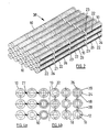
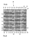
- FIGs 2 and 3 show a bundle 38 of 18 tubular fuel cell assemblies 10 in six columns of three.
- Each assembly 10 in Figure 3a has two longitudinal series of silver strips 26 with each silver strip 26 associated with a respective cathode layer portion and fuel cell.
- Such an arrangement is also shown in Figure 2 , although, for convenience only, the silver strips 26 have only been shown in the foremost column of three assemblies 10.
- the four fuel cells separated by three circumferential gaps 23 in the cathode layer 20 and the silver mesh 24 in each fuel cell assembly 10 are connected in series by the diagonally opposed longitudinally extending silver strips 26 disposed, in this case, over the mesh 24.
- Two or more of the assemblies 10 in Figures 2 and 3 may be mechanically supported and/or electrically connected at one or both ends and/or between the ends, for example as described with reference to Figure 4 , but are shown physically spaced from each other and without support or connections for clarity.
- FIG 4 two optional methods of mechanically and electrically connecting adjacent assemblies 10 in bundles each comprising three rows of three assemblies are shown in Figures 4a and b , respectively.
- the assemblies 10 in each row are shown connected in parallel
- the assemblies 10 in each column are shown connected in parallel.
- the connectors are formed of silver welded to the interrupted silver strips 26 of Figure 3a , but in Figure 4a they are illustrated as intermittent solid blocks 27 to provide a mechanically rigid link while in Figure 4b they are illustrated as intermittent hollow and flexible connectors 28 to better tolerate variations in shape and size of the assemblies 10.
- either type of connector 27 and 28 may be used to connect the rows and/or columns of tubular fuel cell assemblies and that the assemblies 10 may also be connected at one or both ends.
- the solid blocks 27 or hollow connectors 28 may additionally or only connect adjacent fuel cells in each fuel cell assembly 10 in Figure 3a in series, but in Figure 4 each cell in each tubular assembly 10 is connected not to the adjacent cell on the same assembly 10, but to the nearest neighbour in the next column or row of tubular assemblies 10, ie. only in parallel.
- the following examples illustrate, without limiting the invention, different processes for extruding an anode layer cermet comprising NiO/10 mol% yttria-zirconia (10YSZ) on to the outside surface of an expanded Ni-mesh current collector tube such that the current collector tube is partly embedded in the extruded anode layer in order to reinforce the dried, porous anode layer.
- the examples also illustrate the formation of a 10YSZ electrolyte layer on the anode layer, but do not illustrate the formation of a porous cathode layer on the electrolyte layer or of a cathode-side current collector on the cathode layer.
- the formation of the cathode layer and cathode-side current collector may be substantially as already described.
- This example uses an organic solvent based system for extrusion of NiO/10YSZ onto a Ni mesh tube and subsequent application of a 10YSZ electrolyte layer to the outside by coating.
- a tube formed from expanded Ni mesh (5mm diameter) was pre-oxidised by heat-treatment in air at 400°C for 1 hour.
- An extrusion mixture was made by combining NiO and 10YSZ powders with binder, plasticiser and solvent.
- the NiO had a nominal particle size of 1 ⁇ m with a range of 0.6 - 10 ⁇ m.
- the 10YSZ had a nominal size of 1 ⁇ m with a size range of 0.6 - 4.0 ⁇ m.
- the ratio of NiO to 10YSZ powders was chosen to achieve a 50vol% Ni-10YSZ cermet.
- the powders were milled together with the binder and plasticiser in a high-shear mixer to produce a paste having a dough-like consistency.
- the paste consisted of (by weight) 81 % NiO/10YSZ powder, 11 % polyvinyl butiral (PVB) binder and 8% benzyl butyl phtalate (BBP) plasticiser which was mixed with solvent at a solids to solvent ratio of about 9:1 by weight.
- the solvent was one third by weight methyl ethyl ketone and two thirds toluene.
- the formulation may be varied as required in the range 77-84 weight % powder, 8-14 weight % PVB and 6-9 weight % BBP and the amount of solvent adjusted to achieve the required dough-like consistency for extrusion.
- the Ni-tube was passed through the centre of an extrusion die and a 300 micron thick layer of the paste was extruded onto the Ni tube. After drying, the extruded structure with the Ni tube partly embedded in the cermet layer was sintered at 1400°C. A 15 micron thick 10YSZ electrolyte layer was then deposited by slurry coating onto the 2-layer structure and sintered at 1400°C.
- the 10YSZ slip used for the slurry coating was prepared in the same manner as the NiO/10YSZ paste, using the same proportions of PVB binder and BBP plasticiser to the weight of powder. However in order to produce a lower viscosity in the slip, compared to the paste, the solids to solvent ratio was reduced to about 7:3, the exact proportion being adjusted to achieve the required rheology characteristics.
- This example used a water based system for extrusion of NiO/10YSZ onto a Ni mesh tube and subsequent application of a 10YSZ electrolyte layer to the outside by coating.
- a tube formed from expanded Ni mesh (5mm diameter) was pre-oxidised as for Example 1 above.
- An extrusion mixture was made by combining the NiO and 10YSZ powders described in Example 1 with binder, plasticiser and water. The ratio of NiO to 10YSZ powders was chosen to achieve a 50vol% Ni-10YSZ cermet. The powders were milled together with the binder and plasticiser in a high-shear mixer to produce a paste having a dough-like consistency.
- the paste consisted of (by weight) 87% NiO/10YSZ powder, 9% polyvinyl alcohol (PVA) binder and 4% glycerol plasticiser which was mixed with water at a solids to water ratio of about 9:1 by weight.
- the formulation may be varied as required in the range 83-90 weight % powder, 6-12 weight% PVA and 3-6 weight % glycerol and the amount of water adjusted to achieve the required dough-like consistency for extrusion.
- the Ni-tube was passed through the center of an extrusion die and a 300 micron thick layer of the paste was extruded onto the Ni tube. After drying, the extruded structure with the Ni tube partly embedded in the cermet layer was sintered at 1400°C. A 15 micron thick 10YSZ electrolyte layer was deposited by slurry coating onto the 2-layer structure and sintered at 1400°C.
- the 10YSZ slip used for the slurry coating was prepared in the same manner as the NiO/10YSZ paste, using the same proportions of PVA binder and glycerol plasticiser to the weight of powder. However in order to produce a lower viscosity in the slip, compared to the paste, the solids to water ratio was reduced to about 7:3, the exact proportion being adjusted to achieve the required rheology characteristics.
- This example used an organic solvent based system for co-extrusion of a NiO/10YSZ layer and a 10YSZ layer onto a Ni mesh tube.
- a tube formed from expanded Ni mesh was pre-oxidised as for Examples 1 and 2.
- a paste of Ni-10YSZ was prepared as described for Example 1.
- a paste of 10YSZ was prepared in the same manner as for the 10YSZ slip described in Example 1 except that the solids to solvent ratio was higher at about 9:1 in order to produce a paste of a dough-like consistency.
- the Ni-tube was passed through the centre of an extrusion die and a 300 micron thick NiO/10YSZ and a 15 micron thick 10YSZ layer were co-extruded onto the Ni tube.
- the obtained 3-layer structure with the Ni tube partly embedded in the cermet layer was sintered at 1400°C.
- This example used a water based system for co-extrusion of a NiO/10YSZ layer and a 10YSZ layer onto a Ni mesh tube.
- a tube formed from expanded Ni mesh was pre-oxidised as for the above Examples.
- a paste of Ni-10YSZ was prepared as described for Example 2.
- a paste of 10YSZ was prepared in the same manner as for the 10YSZ slip described in Example 2 except that the solids to water ratio was higher at about 9:1 in order to produce a paste of a dough-like consistency.
- the Ni-tube was passed through the center of an extrusion die and a 300 micron thick NiO/10YSZ and a 15 micron thick 10YSZ layer were co-extruded onto the Ni tube.
- the obtained 3-layer structure with the Ni tube partly embedded in the cermet layer was sintered at 1400°C.
- tubular fuel cells described herein are of circular cross-section, this is not essential and they may be of any suitable cross-section.
- the terms "tubular” and “tube” as used herein shall be construed accordingly.
Landscapes
- Chemical & Material Sciences (AREA)
- Engineering & Computer Science (AREA)
- General Chemical & Material Sciences (AREA)
- Electrochemistry (AREA)
- Chemical Kinetics & Catalysis (AREA)
- Sustainable Development (AREA)
- Sustainable Energy (AREA)
- Life Sciences & Earth Sciences (AREA)
- Manufacturing & Machinery (AREA)
- Materials Engineering (AREA)
- Composite Materials (AREA)
- Fuel Cell (AREA)
- Inert Electrodes (AREA)
Applications Claiming Priority (3)
| Application Number | Priority Date | Filing Date | Title |
|---|---|---|---|
| AUPQ315499 | 1999-09-29 | ||
| AUPQ3154A AUPQ315499A0 (en) | 1999-09-29 | 1999-09-29 | Fuel cell assembly |
| PCT/AU2000/001187 WO2001024300A1 (en) | 1999-09-29 | 2000-09-28 | Fuel cell assembly |
Publications (3)
| Publication Number | Publication Date |
|---|---|
| EP1236236A1 EP1236236A1 (en) | 2002-09-04 |
| EP1236236A4 EP1236236A4 (en) | 2005-07-20 |
| EP1236236B1 true EP1236236B1 (en) | 2010-03-17 |
Family
ID=3817318
Family Applications (1)
| Application Number | Title | Priority Date | Filing Date |
|---|---|---|---|
| EP00967438A Expired - Lifetime EP1236236B1 (en) | 1999-09-29 | 2000-09-28 | Fuel cell assembly |
Country Status (7)
| Country | Link |
|---|---|
| EP (1) | EP1236236B1 (enExample) |
| JP (1) | JP2003510788A (enExample) |
| AT (1) | ATE461530T1 (enExample) |
| AU (1) | AUPQ315499A0 (enExample) |
| CA (1) | CA2386059C (enExample) |
| DE (1) | DE60044033D1 (enExample) |
| WO (1) | WO2001024300A1 (enExample) |
Cited By (1)
| Publication number | Priority date | Publication date | Assignee | Title |
|---|---|---|---|---|
| TWI575109B (zh) * | 2015-12-14 | 2017-03-21 | 遠東科技大學 | 燃料電池電解質成形方法以及高緻密之燃料電池電解質 |
Families Citing this family (47)
| Publication number | Priority date | Publication date | Assignee | Title |
|---|---|---|---|---|
| WO2001091218A2 (en) * | 2000-05-22 | 2001-11-29 | Acumentrics Corporation | Electrode-supported solid state electrochemical cell |
| JP4252453B2 (ja) * | 2001-09-26 | 2009-04-08 | 日本碍子株式会社 | 電気化学セルおよびその製造方法 |
| US6893762B2 (en) | 2002-01-16 | 2005-05-17 | Alberta Research Council, Inc. | Metal-supported tubular micro-fuel cell |
| GB0201800D0 (en) * | 2002-01-26 | 2002-03-13 | Rolls Royce Plc | A fuel cell module |
| US7736772B2 (en) | 2002-02-14 | 2010-06-15 | Alberta Research Council, Inc. | Tubular solid oxide fuel cell stack |
| WO2003071624A2 (en) | 2002-02-20 | 2003-08-28 | Acumentrics Corporation | Fuel cell stacking and sealing |
| DE10224783A1 (de) * | 2002-06-04 | 2004-01-08 | Höhberger, Ulrich Felix Hermann, Dipl.-Ing. | Hohlleiter-Brennstoffzellenelement mit Leiteranordnung und Verfahren zur Herstellung |
| US7153601B2 (en) * | 2002-10-29 | 2006-12-26 | Hewlett-Packard Development Company, L.P. | Fuel cell with embedded current collector |
| JP4072049B2 (ja) * | 2002-12-25 | 2008-04-02 | 京セラ株式会社 | 燃料電池セル及び燃料電池 |
| US7157172B2 (en) * | 2003-05-23 | 2007-01-02 | Siemens Power Generation, Inc. | Combination nickel foam expanded nickel screen electrical connection supports for solid oxide fuel cells |
| JP2005353484A (ja) | 2004-06-11 | 2005-12-22 | Toyota Motor Corp | チューブ型燃料電池用膜電極複合体およびチューブ型燃料電池用集電体 |
| JP2005353489A (ja) * | 2004-06-11 | 2005-12-22 | Toyota Motor Corp | チューブ型燃料電池用膜電極複合体 |
| JP2006179222A (ja) * | 2004-12-21 | 2006-07-06 | Shinko Electric Ind Co Ltd | 燃料電池 |
| JP2006179277A (ja) * | 2004-12-22 | 2006-07-06 | Shinko Electric Ind Co Ltd | 燃料電池 |
| JP4957545B2 (ja) * | 2005-02-04 | 2012-06-20 | トヨタ自動車株式会社 | 燃料電池モジュール及び該燃料電池モジュールを備える燃料電池 |
| US8709674B2 (en) | 2005-04-29 | 2014-04-29 | Alberta Research Council Inc. | Fuel cell support structure |
| JP2007012293A (ja) * | 2005-06-28 | 2007-01-18 | Think Tank Phoenix:Kk | 固体電解質燃料電池用電極構造 |
| JP5061440B2 (ja) | 2005-09-08 | 2012-10-31 | トヨタ自動車株式会社 | 燃料電池の製造方法及び燃料電池の製造装置 |
| US8153318B2 (en) | 2006-11-08 | 2012-04-10 | Alan Devoe | Method of making a fuel cell device |
| AU2006311545B2 (en) | 2005-11-08 | 2011-11-17 | Alan Devoe | Solid oxid fuel cell device comprising an elongated substrate with a hot and a cold portion |
| GB0602842D0 (en) * | 2006-02-14 | 2006-03-22 | Rolls Royce Plc | A Solid Oxide Fuel Cell And A Solid Oxide Fuel Cell Module |
| US8293415B2 (en) | 2006-05-11 | 2012-10-23 | Alan Devoe | Solid oxide fuel cell device and system |
| US8278013B2 (en) | 2007-05-10 | 2012-10-02 | Alan Devoe | Fuel cell device and system |
| US20080292918A1 (en) | 2007-05-25 | 2008-11-27 | Caine Finnerty | Electrochemical system having multiple independent circuits |
| EP2160783B1 (en) * | 2007-05-25 | 2013-08-21 | NanoDynamics Energy, Inc. | Method to operate fuel cells having multiple independent circuits |
| JP4776606B2 (ja) * | 2007-10-25 | 2011-09-21 | 京セラ株式会社 | 燃料電池 |
| US8227128B2 (en) | 2007-11-08 | 2012-07-24 | Alan Devoe | Fuel cell device and system |
| US20090152107A1 (en) * | 2007-12-17 | 2009-06-18 | David Matthew Reed | Current collector structure |
| US8343684B2 (en) | 2008-03-07 | 2013-01-01 | Alan Devoe | Fuel cell device and system |
| JP5273584B2 (ja) * | 2008-07-03 | 2013-08-28 | Toto株式会社 | 固体酸化物形燃料電池セルと固体酸化物形燃料電池セルユニット、及びそれを備える燃料電池モジュール |
| WO2010062639A1 (en) | 2008-10-28 | 2010-06-03 | Alan Devoe | Fuel cell device and system |
| US8465630B2 (en) | 2008-11-10 | 2013-06-18 | Praxair Technology, Inc. | Oxygen separation assembly and method |
| WO2010077683A1 (en) | 2008-12-08 | 2010-07-08 | Nextech Materials, Ltd. | Current collectors for solid oxide fuel cell stacks |
| KR101053227B1 (ko) * | 2009-04-20 | 2011-08-01 | 주식회사 포스비 | 평관형 구조체를 이용한 고체산화물 연료전지용 스택 |
| WO2011041264A1 (en) * | 2009-09-29 | 2011-04-07 | Ut-Battelle, Llc | Wire mesh current collector, solid state electrochemical devices including the same, and methods of making the same |
| JP5617572B2 (ja) * | 2010-12-01 | 2014-11-05 | 住友電気工業株式会社 | ガス分解素子、ガス分解素子の製造方法及び発電装置 |
| KR102094799B1 (ko) | 2011-11-30 | 2020-04-14 | 알랜 드보 | 연료전지 장치 |
| GB2498055B (en) * | 2011-11-30 | 2018-03-07 | Bosch Gmbh Robert | Fuel cell system |
| US9023555B2 (en) | 2012-02-24 | 2015-05-05 | Alan Devoe | Method of making a fuel cell device |
| JP6219856B2 (ja) | 2012-02-24 | 2017-10-25 | アラン・デヴォー | 燃料電池デバイスを作製する方法 |
| JP6199680B2 (ja) * | 2012-09-28 | 2017-09-20 | 株式会社日本触媒 | 固体酸化物形燃料電池のハーフセル及び固体酸化物形燃料電池セル |
| JP6018639B2 (ja) * | 2012-09-28 | 2016-11-02 | 株式会社日本触媒 | 固体酸化物形燃料電池ハーフセル及び固体酸化物形燃料電池 |
| JP6340977B2 (ja) * | 2014-07-17 | 2018-06-13 | 株式会社デンソー | 燃料電池 |
| JP6212003B2 (ja) * | 2014-07-30 | 2017-10-11 | 株式会社ノリタケカンパニーリミテド | 円筒型sofcハーフセルグリーン体およびその焼成物である円筒型sofc |
| KR101707063B1 (ko) * | 2015-11-26 | 2017-02-17 | 재단법인대구경북과학기술원 | 관형 연료 전지 및 그 스택 |
| JP7208764B2 (ja) * | 2018-10-31 | 2023-01-19 | 株式会社ノリタケカンパニーリミテド | 固体酸化物形燃料電池とこれに用いる集電部形成用材料 |
| CN110619792A (zh) * | 2019-09-23 | 2019-12-27 | 佛山索弗克氢能源有限公司 | 便携式燃料电池教学仪器 |
Family Cites Families (6)
| Publication number | Priority date | Publication date | Assignee | Title |
|---|---|---|---|---|
| US3522097A (en) * | 1967-06-12 | 1970-07-28 | Gen Electric | Silver-palladium cathodic current collector for high temperature fuel cells |
| ZA817158B (en) * | 1980-12-22 | 1983-01-26 | Westinghouse Electric Corp | High temperature solid electrolyte fuel cell configurations and interconnections |
| JP2528989B2 (ja) * | 1990-02-15 | 1996-08-28 | 日本碍子株式会社 | 固体電解質型燃料電池 |
| US5085742A (en) * | 1990-10-15 | 1992-02-04 | Westinghouse Electric Corp. | Solid oxide electrochemical cell fabrication process |
| US5827620A (en) * | 1993-03-20 | 1998-10-27 | Keele University | Solid oxide fuel cell structures |
| JP3487630B2 (ja) * | 1994-02-23 | 2004-01-19 | 株式会社フジクラ | 円筒形固体電解質燃料電池 |
-
1999
- 1999-09-29 AU AUPQ3154A patent/AUPQ315499A0/en not_active Abandoned
-
2000
- 2000-09-28 JP JP2001527389A patent/JP2003510788A/ja active Pending
- 2000-09-28 DE DE60044033T patent/DE60044033D1/de not_active Expired - Lifetime
- 2000-09-28 EP EP00967438A patent/EP1236236B1/en not_active Expired - Lifetime
- 2000-09-28 AT AT00967438T patent/ATE461530T1/de not_active IP Right Cessation
- 2000-09-28 CA CA002386059A patent/CA2386059C/en not_active Expired - Fee Related
- 2000-09-28 WO PCT/AU2000/001187 patent/WO2001024300A1/en not_active Ceased
Cited By (1)
| Publication number | Priority date | Publication date | Assignee | Title |
|---|---|---|---|---|
| TWI575109B (zh) * | 2015-12-14 | 2017-03-21 | 遠東科技大學 | 燃料電池電解質成形方法以及高緻密之燃料電池電解質 |
Also Published As
| Publication number | Publication date |
|---|---|
| JP2003510788A (ja) | 2003-03-18 |
| ATE461530T1 (de) | 2010-04-15 |
| AUPQ315499A0 (en) | 1999-10-21 |
| CA2386059A1 (en) | 2001-04-05 |
| EP1236236A4 (en) | 2005-07-20 |
| WO2001024300A1 (en) | 2001-04-05 |
| EP1236236A1 (en) | 2002-09-04 |
| CA2386059C (en) | 2009-07-07 |
| DE60044033D1 (de) | 2010-04-29 |
Similar Documents
| Publication | Publication Date | Title |
|---|---|---|
| EP1236236B1 (en) | Fuel cell assembly | |
| US6623881B2 (en) | High performance solid electrolyte fuel cells | |
| US6852436B2 (en) | High performance solid electrolyte fuel cells | |
| US7588856B2 (en) | Resistive-varying electrode structure | |
| EP2224520B1 (en) | Horizontally-striped solid-oxide fuel battery cell stack and fuel battery | |
| US7285347B2 (en) | Anode-supported flat-tubular solid oxide fuel cell stack and fabrication method of the same | |
| US20040121222A1 (en) | Crack-resistant anode-supported fuel cell | |
| JPH0159705B2 (enExample) | ||
| US20080254335A1 (en) | Porous bi-tubular solid state electrochemical device | |
| US8389180B2 (en) | Electrolytic/fuel cell bundles and systems including a current collector in communication with an electrode thereof | |
| EP2446493A1 (en) | Tubular solid oxide fuel cells with porous metal supports and ceramic interconnections | |
| JP5192723B2 (ja) | 横縞型燃料電池セル及び燃料電池 | |
| KR20120021850A (ko) | 연료극 지지체식 평관형 고체산화물 연료전지 및 그 제조방법 | |
| JP2004152585A (ja) | 燃料電池セル及び燃料電池 | |
| JP4057822B2 (ja) | 燃料電池セル及びセルスタック並びに燃料電池 | |
| AU780681B2 (en) | Fuel cell assembly | |
| EP4546475A1 (en) | Metal-supported fuel cell structure | |
| JPH10106611A (ja) | 固体電解質型燃料電池 | |
| JP2021086786A (ja) | 電気化学反応単セルおよび電気化学反応セルスタック | |
| US9005845B2 (en) | Solid oxide fuel cell and manufacturing method thereof | |
| US10680270B2 (en) | Fuel cell ink trace interconnect | |
| US20190157705A1 (en) | Multiple fuel cell secondary interconnect bonding pads and wires | |
| JP2000106204A (ja) | 固体電解質型燃料電池の集電体およびその製造方法ならびにこれを用いた固体電解質型燃料電池 | |
| JP2000182643A (ja) | 固体電解質型燃料電池 |
Legal Events
| Date | Code | Title | Description |
|---|---|---|---|
| PUAI | Public reference made under article 153(3) epc to a published international application that has entered the european phase |
Free format text: ORIGINAL CODE: 0009012 |
|
| 17P | Request for examination filed |
Effective date: 20020409 |
|
| AK | Designated contracting states |
Kind code of ref document: A1 Designated state(s): AT BE CH CY DE DK ES FI FR GB GR IE IT LI LU MC NL PT SE |
|
| AX | Request for extension of the european patent |
Free format text: AL;LT;LV;MK;RO;SI |
|
| RIC1 | Information provided on ipc code assigned before grant |
Ipc: 7H 01M 8/24 B Ipc: 7H 01M 8/02 A Ipc: 7H 01M 8/12 B |
|
| A4 | Supplementary search report drawn up and despatched |
Effective date: 20050603 |
|
| 17Q | First examination report despatched |
Effective date: 20051107 |
|
| GRAP | Despatch of communication of intention to grant a patent |
Free format text: ORIGINAL CODE: EPIDOSNIGR1 |
|
| GRAJ | Information related to disapproval of communication of intention to grant by the applicant or resumption of examination proceedings by the epo deleted |
Free format text: ORIGINAL CODE: EPIDOSDIGR1 |
|
| GRAP | Despatch of communication of intention to grant a patent |
Free format text: ORIGINAL CODE: EPIDOSNIGR1 |
|
| GRAS | Grant fee paid |
Free format text: ORIGINAL CODE: EPIDOSNIGR3 |
|
| GRAA | (expected) grant |
Free format text: ORIGINAL CODE: 0009210 |
|
| AK | Designated contracting states |
Kind code of ref document: B1 Designated state(s): AT BE CH CY DE DK ES FI FR GB GR IE IT LI LU MC NL PT SE |
|
| REG | Reference to a national code |
Ref country code: GB Ref legal event code: FG4D |
|
| REG | Reference to a national code |
Ref country code: CH Ref legal event code: EP |
|
| REG | Reference to a national code |
Ref country code: IE Ref legal event code: FG4D |
|
| REF | Corresponds to: |
Ref document number: 60044033 Country of ref document: DE Date of ref document: 20100429 Kind code of ref document: P |
|
| REG | Reference to a national code |
Ref country code: NL Ref legal event code: VDEP Effective date: 20100317 |
|
| PG25 | Lapsed in a contracting state [announced via postgrant information from national office to epo] |
Ref country code: AT Free format text: LAPSE BECAUSE OF FAILURE TO SUBMIT A TRANSLATION OF THE DESCRIPTION OR TO PAY THE FEE WITHIN THE PRESCRIBED TIME-LIMIT Effective date: 20100317 Ref country code: FI Free format text: LAPSE BECAUSE OF FAILURE TO SUBMIT A TRANSLATION OF THE DESCRIPTION OR TO PAY THE FEE WITHIN THE PRESCRIBED TIME-LIMIT Effective date: 20100317 |
|
| PG25 | Lapsed in a contracting state [announced via postgrant information from national office to epo] |
Ref country code: SE Free format text: LAPSE BECAUSE OF FAILURE TO SUBMIT A TRANSLATION OF THE DESCRIPTION OR TO PAY THE FEE WITHIN THE PRESCRIBED TIME-LIMIT Effective date: 20100317 Ref country code: NL Free format text: LAPSE BECAUSE OF FAILURE TO SUBMIT A TRANSLATION OF THE DESCRIPTION OR TO PAY THE FEE WITHIN THE PRESCRIBED TIME-LIMIT Effective date: 20100317 Ref country code: GR Free format text: LAPSE BECAUSE OF FAILURE TO SUBMIT A TRANSLATION OF THE DESCRIPTION OR TO PAY THE FEE WITHIN THE PRESCRIBED TIME-LIMIT Effective date: 20100618 Ref country code: ES Free format text: LAPSE BECAUSE OF FAILURE TO SUBMIT A TRANSLATION OF THE DESCRIPTION OR TO PAY THE FEE WITHIN THE PRESCRIBED TIME-LIMIT Effective date: 20100628 Ref country code: CY Free format text: LAPSE BECAUSE OF FAILURE TO SUBMIT A TRANSLATION OF THE DESCRIPTION OR TO PAY THE FEE WITHIN THE PRESCRIBED TIME-LIMIT Effective date: 20100317 Ref country code: BE Free format text: LAPSE BECAUSE OF FAILURE TO SUBMIT A TRANSLATION OF THE DESCRIPTION OR TO PAY THE FEE WITHIN THE PRESCRIBED TIME-LIMIT Effective date: 20100317 |
|
| PGFP | Annual fee paid to national office [announced via postgrant information from national office to epo] |
Ref country code: IT Payment date: 20100914 Year of fee payment: 11 Ref country code: FR Payment date: 20100921 Year of fee payment: 11 |
|
| PGFP | Annual fee paid to national office [announced via postgrant information from national office to epo] |
Ref country code: GB Payment date: 20100922 Year of fee payment: 11 |
|
| PLBE | No opposition filed within time limit |
Free format text: ORIGINAL CODE: 0009261 |
|
| STAA | Information on the status of an ep patent application or granted ep patent |
Free format text: STATUS: NO OPPOSITION FILED WITHIN TIME LIMIT |
|
| PG25 | Lapsed in a contracting state [announced via postgrant information from national office to epo] |
Ref country code: PT Free format text: LAPSE BECAUSE OF FAILURE TO SUBMIT A TRANSLATION OF THE DESCRIPTION OR TO PAY THE FEE WITHIN THE PRESCRIBED TIME-LIMIT Effective date: 20100719 Ref country code: DK Free format text: LAPSE BECAUSE OF FAILURE TO SUBMIT A TRANSLATION OF THE DESCRIPTION OR TO PAY THE FEE WITHIN THE PRESCRIBED TIME-LIMIT Effective date: 20100317 |
|
| 26N | No opposition filed |
Effective date: 20101220 |
|
| PGFP | Annual fee paid to national office [announced via postgrant information from national office to epo] |
Ref country code: DE Payment date: 20100922 Year of fee payment: 11 |
|
| PG25 | Lapsed in a contracting state [announced via postgrant information from national office to epo] |
Ref country code: MC Free format text: LAPSE BECAUSE OF NON-PAYMENT OF DUE FEES Effective date: 20100930 |
|
| REG | Reference to a national code |
Ref country code: CH Ref legal event code: PL |
|
| PG25 | Lapsed in a contracting state [announced via postgrant information from national office to epo] |
Ref country code: IE Free format text: LAPSE BECAUSE OF NON-PAYMENT OF DUE FEES Effective date: 20100928 Ref country code: CH Free format text: LAPSE BECAUSE OF NON-PAYMENT OF DUE FEES Effective date: 20100930 Ref country code: LI Free format text: LAPSE BECAUSE OF NON-PAYMENT OF DUE FEES Effective date: 20100930 |
|
| GBPC | Gb: european patent ceased through non-payment of renewal fee |
Effective date: 20110928 |
|
| PG25 | Lapsed in a contracting state [announced via postgrant information from national office to epo] |
Ref country code: IT Free format text: LAPSE BECAUSE OF NON-PAYMENT OF DUE FEES Effective date: 20110928 |
|
| REG | Reference to a national code |
Ref country code: FR Ref legal event code: ST Effective date: 20120531 |
|
| PG25 | Lapsed in a contracting state [announced via postgrant information from national office to epo] |
Ref country code: DE Free format text: LAPSE BECAUSE OF NON-PAYMENT OF DUE FEES Effective date: 20120403 |
|
| REG | Reference to a national code |
Ref country code: DE Ref legal event code: R119 Ref document number: 60044033 Country of ref document: DE Effective date: 20120403 |
|
| PG25 | Lapsed in a contracting state [announced via postgrant information from national office to epo] |
Ref country code: FR Free format text: LAPSE BECAUSE OF NON-PAYMENT OF DUE FEES Effective date: 20110930 Ref country code: GB Free format text: LAPSE BECAUSE OF NON-PAYMENT OF DUE FEES Effective date: 20110928 |
|
| PG25 | Lapsed in a contracting state [announced via postgrant information from national office to epo] |
Ref country code: LU Free format text: LAPSE BECAUSE OF NON-PAYMENT OF DUE FEES Effective date: 20100928 |