EP1235666B1 - Langhaarschneidsystem - Google Patents
Langhaarschneidsystem Download PDFInfo
- Publication number
- EP1235666B1 EP1235666B1 EP00954578A EP00954578A EP1235666B1 EP 1235666 B1 EP1235666 B1 EP 1235666B1 EP 00954578 A EP00954578 A EP 00954578A EP 00954578 A EP00954578 A EP 00954578A EP 1235666 B1 EP1235666 B1 EP 1235666B1
- Authority
- EP
- European Patent Office
- Prior art keywords
- cutting blade
- cutting
- long
- cutter unit
- unit according
- Prior art date
- Legal status (The legal status is an assumption and is not a legal conclusion. Google has not performed a legal analysis and makes no representation as to the accuracy of the status listed.)
- Expired - Lifetime
Links
- 238000009966 trimming Methods 0.000 title description 2
- 238000005520 cutting process Methods 0.000 claims abstract description 205
- 230000036346 tooth eruption Effects 0.000 claims abstract description 20
- 238000000034 method Methods 0.000 claims abstract description 5
- 230000008569 process Effects 0.000 claims abstract description 3
- 238000005452 bending Methods 0.000 claims description 48
- 238000004049 embossing Methods 0.000 claims description 8
- 238000005096 rolling process Methods 0.000 claims description 7
- 230000006978 adaptation Effects 0.000 claims description 5
- 239000000463 material Substances 0.000 description 5
- 230000003993 interaction Effects 0.000 description 4
- 230000008859 change Effects 0.000 description 3
- 230000008878 coupling Effects 0.000 description 3
- 238000010168 coupling process Methods 0.000 description 3
- 238000005859 coupling reaction Methods 0.000 description 3
- 230000000694 effects Effects 0.000 description 3
- 238000004519 manufacturing process Methods 0.000 description 3
- 230000007704 transition Effects 0.000 description 3
- 230000008901 benefit Effects 0.000 description 2
- 238000009434 installation Methods 0.000 description 2
- 230000005540 biological transmission Effects 0.000 description 1
- 230000000052 comparative effect Effects 0.000 description 1
- 230000001143 conditioned effect Effects 0.000 description 1
- 238000009826 distribution Methods 0.000 description 1
- 238000005516 engineering process Methods 0.000 description 1
- 230000000977 initiatory effect Effects 0.000 description 1
- 238000013532 laser treatment Methods 0.000 description 1
- 230000013011 mating Effects 0.000 description 1
- 238000005259 measurement Methods 0.000 description 1
- 230000002093 peripheral effect Effects 0.000 description 1
- 230000000284 resting effect Effects 0.000 description 1
- 239000007787 solid Substances 0.000 description 1
- 238000011282 treatment Methods 0.000 description 1
Images



Classifications
-
- B—PERFORMING OPERATIONS; TRANSPORTING
- B26—HAND CUTTING TOOLS; CUTTING; SEVERING
- B26B—HAND-HELD CUTTING TOOLS NOT OTHERWISE PROVIDED FOR
- B26B19/00—Clippers or shavers operating with a plurality of cutting edges, e.g. hair clippers, dry shavers
- B26B19/02—Clippers or shavers operating with a plurality of cutting edges, e.g. hair clippers, dry shavers of the reciprocating-cutter type
- B26B19/04—Cutting heads therefor; Cutters therefor; Securing equipment thereof
- B26B19/10—Cutting heads therefor; Cutters therefor; Securing equipment thereof involving two or more different types of reciprocating cutting elements, e.g. a pair of toothed shearing elements combined with a pair of perforated cutting elements or a combined toothed and perforated cutting assembly
Definitions
- the invention relates to a long hair trimmer in the preamble of claim 1 specified type.
- a long hair cutting system of the type mentioned is known from DE 38 19 055 C2.
- This arbitrary curvature of the cutting blade includes an optimal interaction the tread of a dimensionally stable cutting comb.
- a pressure lip acting on the cutting blade from a provided both elastically and plastically deformable material.
- the invention has for its object a long hair trimmer of the aforementioned Art to create, in the assembled state, an optimal installation of cutting comb and cutting blade is guaranteed.
- this object is achieved with a long hair trimmer of the type mentioned Kind solved by the features specified in claim 1.
- a major advantage of the solutions according to the invention is that in relation to the tread of a cutting comb an individual adjustment of the contact surface of the and movable cutting blade can be produced.
- one Cutting blades are available in two different manufacturing processes, without one Material removal on the cutting blade, the cutting blade the required Force curvature or curvatures in such a way that ensuring a necessary Restoring force or the elasticity of the curved cutting blade an adjustment and slidable contact of the cutting surface of the cutting blade with the tread of the Cutting comb is guaranteed.
- a preferred embodiment of the invention is characterized in that the curvature the contact surface of the cutting blade by a series of arc elements the same and different curvature is determined, the connecting the arch elements Transitions as bending points of the cutting blade for the adjustment of the contact surface of the Cutting blade to the shape of the tread of the cutting comb under the influence of the pressure of the spring element are provided.
- This embodiment is already an effective one Adjustment of the contact surface on the cutting blade to the shape of the tread of the Cutting comb in a division of the longitudinal extent of the cutting blade in at least guaranteed three arch elements.
- two curvatures with matching radii and one curvature with this deviating radius can be provided.
- the adjustment of the contact surface of the cutting blade to the shape of the tread of the cutting comb is favored in that the Curvature with the deviating radius between two curvatures with the same radii is provided.
- the Curvature of the contact surface of the cutting blade due to a series of curved elements of the same type Curvature is determined, the transitions connecting the arch elements as Bending points of the cutting blade for adapting the contact surface of the cutting blade to the Shape of the tread of the cutting comb under the influence of the pressure of the spring element are provided.
- This embodiment is particularly suitable for cutting blades whose Contact surface to a flat or slightly concave or slightly convex Tread of a cutting comb is assigned.
- this embodiment Particularly suitable for contact with cutting comb treads Show deviations in the surface condition of the tread.
- the longitudinal extent of the Cutting blade is divided into arch elements by at least two bending points.
- the width extension the cutting blade is divided into arch elements by at least one bending point. This measure favors the pressure of the contact surface of the cutting blade against the tread the cutting comb under the influence of the pressure of at least one spring element.
- the bending point by a continuous continuous adjustment of the curvature of an arc shape of an arch element with the curvature of the arch shape of the subsequent arch element is formed. through this adaptation prevents kinking in the curvature of the cutting blade.
- a preferred embodiment of the invention is characterized in that at least two spring elements are provided, such that the distance of a spring element to one end of the cutting blade is equal to the distance of the other spring element to the other End is. In a further embodiment of this embodiment it is provided that the Distance of the spring elements to each other is substantially equal to the distance of a spring element to one end of the cutting blade. This measure favors the deformation the curvature of the cutting blade to the cutting comb while maintaining it Restoring force or elasticity and brings about a balanced contact and sliding behavior of the Cutting blade on the cutting comb.
- An advantageous embodiment of the invention is characterized in that the direction of the pressure exertable by a spring element essentially on a bending point is aligned. This favors the change in shape of the respective one following the bending point Cutting blade curvatures. Optimal investment and cutting behavior of cutting comb and cutting blade is ensured by the fact that with bending points provided hardened cutting blade has an elasticity or restoring force that one permanent change in the curvature of the cutting blade under the influence of the pressure counteracts the spring element.
- the arch shape and the bending points the arc elements of the cutting blade by embossing using a stamp and Embossing pads can be produced.
- Another manufacturing process for the cutting blade draws is characterized in that the arc shape and the bending points of the arc elements of the cutting blade can be produced by changing the compressive stress of the rolled skin of the hardened blade are.
- This method has the advantage that the contact surface of the cutting blade is partial and can be changed individually in such a way that the hardened cutting blade is in the rolling skin partial and both the same and different compressive stresses are generated lead to the same and different curvatures of the cutting blade.
- This method is the adaptation of the contact surface of the cutting blade to the tread the cutting comb can be optimally controlled.
- the compressive stress is preferably the Rolling skin by means of a laser beam of constant pulse energy as well as changeable Pulse energy is used to move the cutting blade to the appropriate location on the mating surface to achieve the required compressive stress and consequently curvature.
- Fig. 1 shows a dry shaver TR with a housing 1, in the front Actuator switch 2 and an adjustable long hair trimmer LHS arranged are.
- a socket 3 for connection a power supply cable arranged in the bottom wall of the housing 1 .
- a shaving head is provided on the housing 1, in its housing part G an interchangeable frame WR with at least one cutting element S is detachably attached.
- the housing part G of the shaving head is with two support elements 4 and 5 coupled. The support elements 4 and 5 are together with the housing part G in the arrow directions P movable back and forth in the housing 1.
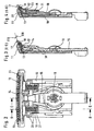
- Fig. 2 shows the front of a long hair cutting system LHS, the components of which a support plate 10 are arranged.
- a support plate 10 On the support plate 10 is a substantially L-shaped trained dimensionally stable cutting comb 11 attached.
- the cutting comb 11 is one Assigned cutting blade 12 on a support body 13 with a molded coupling element 14 is arranged.
- a drive element 15 engages in the coupling element 14 one that can be ozillated, for example, via a swivel bearing 16 provided on the support plate 10 is stored.
- the course is a Sectional representation K-K and a further sectional representation E-E are shown in dash-dot lines, the details of which are apparent from FIGS. 3 and 4.
- FIG. 3 shows the longitudinal section running through the center of the long hair trimming system LHS E-E according to Fig. 2.
- the substantially U-shaped cutting comb 11 is on attached to the inside of the support plate 10.
- the pivotally mounted by means of pivot bearing 16 Drive element 15 is located with the end facing the cutting comb 11 in engagement with the coupling element 14 provided on the support body 13.
- the cutting blade 12 is attached.
- the contact surface 120 of the cutting blade 12 is located on the one hand with the cutting tooth row 18 in contact with the cutting tooth row 17 the cutting comb 11 and on the other hand in contact with the sliding surfaces 27 - by a Recess 28 separately - opposite to row of cutting teeth 17 on cutting comb 11 are provided and together with the row of cutting teeth 17 the tread 110 of the Form cutting comb 11.
- Fig. 4 shows a vertical section K-K through the long hair cutting system LHS, in particular the transmission of the pressure of the spring element 19 to the cutting blade 12 - see Fig. 2 - can be seen.
- the spring element 19 is provided on the support plate 10 Holding elements 21 guided and held.
- One on the support plate 10 by means of a Film hinge molded pressure element 23 transmits the pressure of the spring element 19 on the support body 13.
- the extending parallel to the longitudinal extension of the cutting blade 12 Support body 13 transmits the pressure of the spring element 19 to the cutting blade 12 and causes overcoming the restoring forces of the partial curvatures the cutting blade 12 an adjustment and slidable contact of the contact surface 120
- Cutting blade 12 is produced on the tread 110 of the cutting comb 11.
- Fig. 5 shows a view of the cutting blade 12 receiving side of the cutting comb 11.
- On the inside of the cutting comb 11 are below the row of cutting teeth 17th - Of the cutting teeth only a few cutting teeth are shown - on the vertical Direction extending rear wall two sliding surfaces 27 for the contact of the contact surface a cutting blade 12 is provided. Details of the running through the cutting comb 11 Section B-B indicated by dash-dotted lines are shown in Fig. 6 and are described in more detail below.
- Fig. 6 shows a section through the substantially L-shaped cutting comb 11 with an integrally formed sliding surface 27, which is formed by a recess 28 from which Cutting tooth row 17 formed sliding surface is separated.
- the sliding surface of the row of cutting teeth 17 and the sliding surface 27 together form the running surface 110 of the cutting comb 11 on which the cutting blade 12 back and forth when starting up the long hair cutting system LHS moveable along.
- Fig. 7 shows a schematic representation of a dimensionally stable cutting comb 11 with a flat tread 110 for the abutment of the contact surface 120 Cutting blade having partial curvatures 12.
- the partial curvatures of the Cutting blade 12 are in the embodiment of FIGS. 7, 8 and 9 through the bending points B1 and B2 and by the respective end-side contact of the cutting blade 12 on the Tread 110 of the cutting comb 11 determined.
- the through the bending points B1 and B2 limited mean curvature is as the arch element BE1 and the adjoining lateral ones Curvatures are referred to as arch elements BE2 and BE3.
- the radius of curvature R2 of the arc element BE2 has the same size as the radius of curvature R2 the arch element BE3.
- the radius of curvature R1 of the arc element differs from this BE1 is larger than the radius of curvature R2.
- the bending points B1 and B2 can, for example, by embossing using an embossing stamp and an embossing pad or by changing the compressive stress and tensile stresses of the rolling skin Hardened cutting blade 12 can be produced by means of a laser beam.
- the curvature of the Cutting blade 12 in the region of the distance A is usually of the order of magnitude 0.03 to 0.3 mm.
- the distance A formed by the curvature is preferably in one Range from 0.05mm to 0.15mm.
- two spring elements 19 act accordingly 2 - preferably on the bending points B1 and B2, and bring the curved cutting blade 12 to bear against the cutting comb 11.
- the deformation process the curved cutting blade 12 to the stretched system on the Cutting comb 11 is explained in more detail on the basis of FIG. 7 with reference to FIG. 8.
- the cutting blade In the embodiment according to FIG. 7, 12 initially lies at points E 1 without force and E2 on the cutting comb 11. After initiation of a print by the error elements 19 on the cutting blade 12 preferably on the bending points B1 and B2 of the cutting blade 12, the support forces K1 and K2 rise at points E1 and E2.
- the arch element is curved BE1 in the direction of the tread 110 of the cutting comb 11 up to a system at location E3. Then causes and existing in the spring elements 19 Pressure a movement of the bending points B1 and B2 in the direction of the cutting comb 11, until there is a complete installation of the bending points B1 and B2 as well as the arch surfaces the arc elements BE 1 to BE 3 of the contact surface 120 of the cutting blade 12 comes.
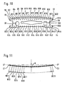
- FIG. 10 shows a view of the contact surface 120 of a cutting blade 12 with a sequence of Arch elements BE1 to BE42 delimited by bending points B1 to B44.
- the bending points B1 through B22 are provided, for example, on a straight line adjacent to one slightly arcuate cutting tooth row 18 of the cutting blade 12 extends.
- This Bending points B1 to B44 are created, for example, by treating the cutting blade 12 generated by laser beams. In the area of the interaction zone of laser beam and The material of the hardened cutting blade 12 is initially partially and heated then cools down. The stresses generated in the material by this treatment cause corresponding curvatures of the cutting blade 12, the size of which by a corresponding Heat balance are controllable at the interaction point.
- two rows R10 and R20 of bending points B1 to B22 on the one hand adjacent to the row of cutting teeth 18 and on the other hand in a relative short distance from the longitudinal edge of the cutting blade 12 is provided.
- the bending points B1 formed by the irradiation points of the laser beam to B22 are by a pulsed solid laser body with a power between 50 to 100 watts and a pulse energy of approx. 1 Nm.
- the bending points B23 to B44 of the R20 series are manufactured in the same way.
- the R10 and R20 series effect a change in shape such that the ends of the cutting blade 12 are viewed in the longitudinal direction raised to a curvature with a central distance A to one of the ends of the Cutting blade 12 connecting secant S *.
- the tooth tips are viewed in the transverse direction the row of cutting teeth 18 and the opposite side of the cutting blade 12 also raised by a distance B. Both changes in shape result in an optimal Adaptation and slidable contact of the contact surface 120 of the cutting blade 12 to the Tread 110 of cutting comb 11.
- FIG. 11 shows a section through the cutting blade 12 according to FIG. 10, for example in the area the R1 series of bending points.
- the arch elements BE1 to BE21 provided here are each limited by bending points B1 to B22.
- the curvature of the contact surface 120 of the Cutting blade 12 in the area of the row of cutting teeth 18 is determined by a sequence of Arch elements BE 1 - BE 21 of the same curvature with a central distance A to one the ends of the cutting blade 12 connecting secant S *.
- the arch elements BE1 - Transitions connecting BE21 are provided as bending points B1-B22, the curvature the arch elements BE1-B22 by applying the respective bending point B1 - B22 was generated by a laser beam with constant pulse energy.
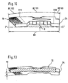
- the width extension BR of the cutting blade 12 is in the longitudinal extension L of the cutting blade by means of two 12 running rows R10 and R20 from bending points B1 to B44 in three arch elements BE101, BE102 and BE103 divided.
- the distance of the R10 series to the outermost Ends is approx. 2.8 mm ⁇ 1 mm
- the distance from the R10 series to the R20 series is approx. 2.8 mm ⁇ 1 mm
- the distance between the R20 series and the outer edge 24 is approximately 1.2 mm ⁇ 1 mm with a width extension BR of approx. 6.8 mm.
- the one by the lining up of the Arch elements BE100, BE101 and BE 102 to a central distance resulting in a secant S * B is 4 ⁇ m in the illustrated embodiment.
- the curvature of the cutting blade 12 in the range of the distance B is usually in the order of 0 to 15 microns and preferably in a range of 3-5 microns.
- FIG. 13 shows a perspective illustration of the cutting blade 12 according to FIG. 12 with a Cut through the middle of the cutting blade 12.
- the through the curvature of the arch elements BE formed maximum distance A to a secant S * - see Fig. 11 - is at illustrated embodiment about 90 microns.
- the bending points B1 to B44 can deviate from the arrangement on one and / or several straight rows R10 and R20 in the respective application depending on the given
- a cutting blade 12 can be provided at other points on the contact surface 120 to generate a direct or indirect effect of the pressure of a Spring element 19 shape-changing curvature.
- Such deviations from an arrangement on a straight row R10, R20 are, if necessary, by comparative Determine measurements on the cutting comb 11 and cutting blade 12 and then to carry out accordingly in terms of production technology.
Landscapes
- Life Sciences & Earth Sciences (AREA)
- Forests & Forestry (AREA)
- Engineering & Computer Science (AREA)
- Mechanical Engineering (AREA)
- Dry Shavers And Clippers (AREA)
- Processing Of Stones Or Stones Resemblance Materials (AREA)
- Harvester Elements (AREA)
- Thermotherapy And Cooling Therapy Devices (AREA)
Description
- Fig. 1
- die Vorderseite eines Rasierapparates mit einem Langhaarschneidsystem,
- Fig. 2
- die Vorderseite eines Langhaarschneidsystems, dessen Bauelemente auf einer Tragplatte angeordnet sind,
- Fig. 3
- einen Längsschnitt E-E durch das Langhaarschneidsystem nach Fig. 2,
- Fig. 4
- einen Längsschnitt K-K durch das Langhaarschneidsystem nach Fig. 2,
- Fig. 5
- eine Sicht auf den Schneidkamm mit angeformten Gleitflächen,
- Fig. 6
- einen vertikalen Schnitt B-B durch den Schneidkamm,
- Fig. 7
- eine schematische Darstellung von Schneidkamm und Schneidklinge mit durch Biegestellen bestimmten Bogenelementen gleicher und unterschiedlicher Krümmung,
- Fig. 8
- einen formstabil ausgebildeten Schneidkamm sowie eine Schneidklinge mit partiellen Krümmungen,
- Fig. 9
- einen formstabilen Schneidkamm mit unter Einwirkung des Druckes zweier Federelemente anliegender Schneidklinge,
- Fig. 10
- die Anlagefläche einer Schneidklinge mit einer Schneidzahnreihe und zwei parallel zueinander verlaufenden Biegestellenreihe,
- Fig. 11
- eine mittels einer Folge von Biegestellen gekrümmte Schneidklinge,
- Fig. 12
- eine perspektivische Darstellung einer Schneidklinge mit Sicht auf die Breitseite der Schneidklinge,
- Fig. 13
- eine perspektivische Darstellung der Schneidklinge nach Fig. 12 mit einem Querschnitt durch die Mitte der Schneidklinge.
Claims (17)
- Langhaarschneidsystem (LHS) für einen Trockenrasierapparat (TR) mit einem formstabil ausgebildeten, eine Schneidzahnreihe (17) aufweisenden Schneidkamm (11) mit wenigstens einer Lauffläche (110) für wenigstens eine Anlagefläche (120) einer eine Schneidzahnreihe (18) aufweisenden, bogenförmig gekrümmten gehärteten Schneidklinge (12), die von einem Druck von wenigstens einem Federelement (19) in Anlage an dem Schneidkamm (11) gehalten ist, dadurch gekennzeichnet, daß die Krümmung der gehärteten Schneidklinge (12) mittels eines Umformverfahrens partiell derart gestaltet ist, daß mittels einer Vielzahl von partiellen Krümmungen sowie deren Rückstettkräften unter Einwirkung des Druckes des Federelementes (19) sowie mittels einer Vielzahl von die Bogenelemente (BE1 bis BE42, BE101 bis BE103) verbindenden Biegestellen (B1 bis B44) eine Anpassung und gleitfähige Anlage der Anlagefläche (120) der Schneidklinge (12) an die Lauffläche (110) des Schneidkammes (11) gewährleistet ist.
- Langhaarschneidsystem nach dem Oberbegriff des Anspruchs 1, dadurch gekennzeichnet, daß die Krümmung der gehärteten Schneidklinge (12) durch mehrere Biegestellen (B1 bis B44) bestimmt ist, und das mittels der Biegestellen (B1 bis B44) sowie der Elastizität der gekrümmten Schneidklinge (12) unter Einwirkung des Druckes des Federelementes (19) eine Anpassung und gleitfähige Anlage der Anlagefläche (120) der Schneidklinge (12) an die Lauffläche (110) des Schneidkammes (11) gewährleistet ist.
- Langhaarschneidsystem nach Anspruch 1 oder 2, dadurch gekennzeichnet, daß die Krümmung der Anlagefläche (120) der Schneidklinge (12) durch eine Folge von Bogenelementen (BE1 bis BE42, BE101 bis BE103) gleicher und unterschiedlicher Krümmung bestimmt ist, wobei die die Bogenelemente (BE1 bis BE42, BE101 bis BE103) verbindenden Übergänge als Biegestellen (B1 bis B44) der Schneidklinge (12) für die Anpassung der Anlagefläche (120) der Schneidklinge (12) an die Form der Lauffläche (110) des Schneidkammes (11) unter Einwirkung des Druckes des Federelementes (19) vorgesehen sind.
- Langhaarschneidsystem nach einem der vorhergehenden Ansprüche dadurch gekennzeichnet, daß die Krümmung der Anlagefläche (120) der Schneidklinge (12) durch eine Folge von Bogenelementen (BE1 bis BE42, BE101 bis BE103) gleicher Krümmung bestimmt ist, wobei die die Bogenelemente (BE1 bis BE42, BE101 bis BE103) verbindenden Übergänge als Biegestellen (B1 bis B44) der Schneidklinge (12) für die Anpassung der Anlagefläche (120) der Schneidklinge (12) an die Form der Lauffläche (110) des Schneidkammes (11) unter Einwirkung des Druckes des Federelementes (19) vorgesehen sind.
- Langhaarschneidsystem nach einem der vorhergehenden Ansprüche, dadurch gekennzeichnet, daß die Längserstreckung (L) der Schneidklinge (12) durch wenigstens zwei Biegestellen (B1, B2) in Bogenelemente (BE1, BE2, BE3, BE101 bis BE103) unterteilt ist.
- Langhaarschneidsystem nach einem der vorhergehenden Ansprüche, dadurch gekennzeichnet, daß parallel zu einer Längserstreckung (L) der Schneidklinge (12) wenigstens zwei Reihen (R10, R20) von Biegestellen (B1 bis B44) vorgesehen sind.
- Langhaarschneidsystem nach einem der vorhergehenden Ansprüche, dadurch gekennzeichnet, daß die Breitenerstreckung (BR) der Schneidklinge (12) durch wenigstens eine Biegestelle (B1) in Bogenelemente (BE1, BE2, BE101 bis BE103) unterteilt ist.
- Langhaarschneidsystem nach einem der vorhergehenden Ansprüche, dadurch gekennzeichnet, daß die Biegestelle (B1 bis B44) durch eine kontinuierliche stetige Anpassung der Krümmung einer Bogenform eines Bogenelementes (BE1 bis BE42, BE101 bis BE103) mit der Krümmung der Bogenform des anschließenden Bogenelementes (BE1 bis BE42, BE101 bis BE103) gebildet ist.
- Langhaarschneidsystem nach einem der vorhergehenden Ansprüche, dadurch gekennzeichnet, daß die Längserstreckung (L) der Schneidklinge (12) durch zwei Biegestellen (B1, B2) in drei Bogenelemente (BE1, BE2, BE3, BE101 bis BE103) unterteilt ist.
- Langhaarschneidsystem nach Anspruch 9, dadurch gekennzeichnet, daß die Krümmung von zwei Bogenelementen (BE2, BE3, BE101, B103) gleich geformt und die Krümmung des weiteren Bogenelementes (BE1-BE100) unterschiedlich geformt zu diesen Krümmungen ausgebildet ist.
- Langhaarschneidsystem nach einem der vorhergehenden Ansprüche, dadurch gekennzeichnet, daß wenigstens zwei Federelemente (19) vorgesehen sind, derart, daß der Abstand eines Federelementes (19) zu einem Ende der Schneidklinge (12) gleich dem Abstand des anderen Federelementes (19) zu dem anderen Ende ist.
- Langhaarschneidsystem nach Anspruch 11, dadurch gekennzeichnet, daß der Abstand der Federelemente (19) zueinander im wesentlichen gleich dem Abstand eines Federelementes (19) zu einem Ende der Schneidklinge (12) ist.
- Langhaarschneidsystem nach einem der vorhergehenden Ansprüche, dadurch gekennzeichnet, daß die Richtung des von einem Federelement (19) ausübbaren Drukkes im wesentlichen auf eine der Biegestellen (B1 bis B44) ausgerichtet ist.
- Langhaaarschneidsystem nach einem der vorhergehenden Ansprüche, dadurch gekennzeichnet, daß die mit Biegestellen (B1 bis B44) versehene gehärtete Schneidklinge (12) eine Elastizität oder Rückstellkraft aufweist, die einer bleibenden Formveränderung der Krümmung der Schneidklinge (12) unter Einwirkung des Druckes des Federelementes (19) entgegenwirkt.
- Langhaarschneidsystem nach einem der vorhergehenden Ansprüche, dadurch gekennzeichnet, daß die Bogenform und die Biegestellen (B1 bis B44) der Bogenelemente (BE1 bis BE42, BE101 bis BE103) der Schneidklinge (12) durch Prägung mittels Prägestempel und Prägekissen herstellbar sind.
- Langhaarschneidsystem nach einem der vorhergehenden Ansprüche, dadurch gekennzeichnet, daß die Bogenform und die Biegestellen (B1 bis B44) der Bogenelemente (BE1 bis BE42, BE101 bis BE103) der Schneidklinge (12) durch Veränderung der Druckspannung der Walzhaut der gehärteten Schneidklinge (12) herstellbar sind.
- Langhaarschneidsystem nach einem der vorhergehenden Ansprüche, dadurch gekennzeichnet, daß die Druckspannung der Walzhaut der gehärteten Schneidklinge (12) mittels Beaufschlagung durch einen Laserstrahl herstellbar ist.
Applications Claiming Priority (3)
| Application Number | Priority Date | Filing Date | Title |
|---|---|---|---|
| DE19944616A DE19944616C1 (de) | 1999-09-17 | 1999-09-17 | Langhaarschneidsystem |
| DE19944616 | 1999-09-17 | ||
| PCT/EP2000/007349 WO2001021361A1 (de) | 1999-09-17 | 2000-07-29 | Langhaarschneidsystem |
Publications (2)
| Publication Number | Publication Date |
|---|---|
| EP1235666A1 EP1235666A1 (de) | 2002-09-04 |
| EP1235666B1 true EP1235666B1 (de) | 2004-02-18 |
Family
ID=7922382
Family Applications (1)
| Application Number | Title | Priority Date | Filing Date |
|---|---|---|---|
| EP00954578A Expired - Lifetime EP1235666B1 (de) | 1999-09-17 | 2000-07-29 | Langhaarschneidsystem |
Country Status (9)
| Country | Link |
|---|---|
| US (1) | US6490799B2 (de) |
| EP (1) | EP1235666B1 (de) |
| JP (1) | JP2003509182A (de) |
| CN (1) | CN1195608C (de) |
| AT (1) | ATE259694T1 (de) |
| AU (1) | AU6698600A (de) |
| DE (2) | DE19944616C1 (de) |
| ES (1) | ES2215709T3 (de) |
| WO (1) | WO2001021361A1 (de) |
Families Citing this family (13)
| Publication number | Priority date | Publication date | Assignee | Title |
|---|---|---|---|---|
| USD479360S1 (en) | 2002-05-31 | 2003-09-02 | Matsushita Electric Works, Ltd. | Electric razor |
| US7536787B2 (en) | 2004-03-30 | 2009-05-26 | Ridgewood Industries Llc | Wet razor and electric trimmer assembly |
| EP2329928B1 (de) * | 2009-12-04 | 2012-07-04 | Braun GmbH | Elektrisch betriebene Haarschneidemaschine |
| US9713877B2 (en) | 2014-11-12 | 2017-07-25 | Medline Industries, Inc. | Clipper head with drag reduction |
| USD779123S1 (en) | 2014-11-12 | 2017-02-14 | Medline Industries, Inc. | Clipper head |
| USD795497S1 (en) | 2016-01-15 | 2017-08-22 | Medline Industries, Inc. | Clipper |
| USD794871S1 (en) | 2016-01-15 | 2017-08-15 | Medline Industries, Inc. | Clipper |
| USD802216S1 (en) | 2016-06-10 | 2017-11-07 | Medline Industries, Inc. | Clipper head |
| USD802217S1 (en) | 2016-06-10 | 2017-11-07 | Medline Industries, Inc. | Clipper head |
| USD802214S1 (en) | 2016-06-10 | 2017-11-07 | Medline Industries, Inc. | Clipper head |
| USD802215S1 (en) | 2016-06-10 | 2017-11-07 | Medline Industries, Inc. | Clipper head |
| EP3381629A1 (de) | 2017-03-28 | 2018-10-03 | Koninklijke Philips N.V. | Kammanordnung, schneidkopf und haarschneidegerät |
| USD1105609S1 (en) | 2022-05-16 | 2025-12-09 | Spectrum Brands, Inc. | Shaver |
Family Cites Families (6)
| Publication number | Priority date | Publication date | Assignee | Title |
|---|---|---|---|---|
| GB1544336A (en) * | 1977-03-11 | 1979-04-19 | Gillette Co | Hair clippers |
| GB2094698B (en) * | 1981-02-13 | 1985-01-23 | Lister Farm Equipment R A Ltd | A clipper blade |
| US4765060A (en) * | 1987-02-17 | 1988-08-23 | Micro Contacts Inc. | Disposable shaver head |
| DE3819055A1 (de) * | 1988-06-04 | 1989-12-07 | Braun Ag | Langhaarschneideinrichtung fuer trockenrasierapparate |
| EP0652085A1 (de) * | 1993-11-10 | 1995-05-10 | Koninklijke Philips Electronics N.V. | Gerät zum Schneiden von Haaren mit einer Zahnschneideinrichtung |
| AU765077B2 (en) * | 1998-12-29 | 2003-09-11 | Kim Laube | Disposable cutting head for clippers |
-
1999
- 1999-09-17 DE DE19944616A patent/DE19944616C1/de not_active Expired - Fee Related
-
2000
- 2000-07-29 WO PCT/EP2000/007349 patent/WO2001021361A1/de not_active Ceased
- 2000-07-29 DE DE50005354T patent/DE50005354D1/de not_active Expired - Fee Related
- 2000-07-29 CN CNB008127921A patent/CN1195608C/zh not_active Expired - Fee Related
- 2000-07-29 JP JP2001524769A patent/JP2003509182A/ja active Pending
- 2000-07-29 AU AU66986/00A patent/AU6698600A/en not_active Abandoned
- 2000-07-29 EP EP00954578A patent/EP1235666B1/de not_active Expired - Lifetime
- 2000-07-29 AT AT00954578T patent/ATE259694T1/de not_active IP Right Cessation
- 2000-07-29 ES ES00954578T patent/ES2215709T3/es not_active Expired - Lifetime
-
2002
- 2002-03-15 US US10/099,632 patent/US6490799B2/en not_active Expired - Fee Related
Also Published As
| Publication number | Publication date |
|---|---|
| ES2215709T3 (es) | 2004-10-16 |
| CN1373699A (zh) | 2002-10-09 |
| US6490799B2 (en) | 2002-12-10 |
| WO2001021361A1 (de) | 2001-03-29 |
| AU6698600A (en) | 2001-04-24 |
| EP1235666A1 (de) | 2002-09-04 |
| US20020092177A1 (en) | 2002-07-18 |
| DE19944616C1 (de) | 2000-12-28 |
| ATE259694T1 (de) | 2004-03-15 |
| CN1195608C (zh) | 2005-04-06 |
| JP2003509182A (ja) | 2003-03-11 |
| DE50005354D1 (de) | 2004-03-25 |
Similar Documents
| Publication | Publication Date | Title |
|---|---|---|
| DE69504963T2 (de) | Sicherheitsrasierer | |
| AT401901B (de) | Gerät zum schneiden von haaren mit einer zahnschneideinrichtung und verfahren zum herstellen eines messers für eine zahnschneideinrichtung eines solchen gerätes | |
| EP0693988B1 (de) | Scherkopf für einen trockenrasierapparat | |
| DE19944616C1 (de) | Langhaarschneidsystem | |
| DE69120900T2 (de) | Rasierapparat | |
| DE68925103T2 (de) | Kombiniertes bandfrisier- und schneidwerkzeug | |
| DE602004009289T2 (de) | Rasierkopf mit hautkontrollmittel | |
| DE3246258A1 (de) | Haarschneidmaschine | |
| EP0603617A1 (de) | Trockenrasierapparat mit einem schwenkbar gelagerten Langhaarschneider | |
| EP1079958A1 (de) | Trockenrasierapparat | |
| WO2008141720A1 (de) | Schneideinrichtung zum schneiden von haaren | |
| EP0416358B1 (de) | Rasierapparatekopf eines Nassrasierapparates | |
| DE102008046072A1 (de) | Scherkopf für einen Rasierapparat | |
| EP0477132B1 (de) | Klingeneinheit mit Führungs/Schutz-Element | |
| DE1174651B (de) | Trockenrasiergeraet mit gegen Federwirkung eindrueckbarer Rasierplatte | |
| DE10248026A1 (de) | Verfahren zur Herstellung einer Friseurschere, sowie Friseurschere | |
| DE60104558T2 (de) | Sicherheitsrasierer | |
| DE8711505U1 (de) | Rasierklingeneinheit | |
| DE2603653A1 (de) | Vorrichtung zum schneiden und stutzen von haaren | |
| EP0008483B1 (de) | Langhaarscherteil, insbesondere für Trockenrasierapparate | |
| DE69308754T2 (de) | Rasiergerät mit einem folienartigen Ober- und Untermesser | |
| DE2937364C2 (de) | ||
| DE2836120A1 (de) | Haarschneidemaschine | |
| DE4405576A1 (de) | Scherkopf für Naßrasierapparate | |
| EP1370397B1 (de) | Schersystem für einen trockenrasierer |
Legal Events
| Date | Code | Title | Description |
|---|---|---|---|
| PUAI | Public reference made under article 153(3) epc to a published international application that has entered the european phase |
Free format text: ORIGINAL CODE: 0009012 |
|
| 17P | Request for examination filed |
Effective date: 20020214 |
|
| AK | Designated contracting states |
Kind code of ref document: A1 Designated state(s): AT BE CH CY DE DK ES FI FR GB GR IE IT LI LU MC NL PT SE |
|
| AX | Request for extension of the european patent |
Free format text: AL;LT;LV;MK;RO;SI |
|
| 17Q | First examination report despatched |
Effective date: 20021001 |
|
| GRAP | Despatch of communication of intention to grant a patent |
Free format text: ORIGINAL CODE: EPIDOSNIGR1 |
|
| GRAS | Grant fee paid |
Free format text: ORIGINAL CODE: EPIDOSNIGR3 |
|
| GRAA | (expected) grant |
Free format text: ORIGINAL CODE: 0009210 |
|
| AK | Designated contracting states |
Kind code of ref document: B1 Designated state(s): AT BE CH CY DE DK ES FI FR GB GR IE IT LI LU MC NL PT SE |
|
| PG25 | Lapsed in a contracting state [announced via postgrant information from national office to epo] |
Ref country code: FI Free format text: LAPSE BECAUSE OF FAILURE TO SUBMIT A TRANSLATION OF THE DESCRIPTION OR TO PAY THE FEE WITHIN THE PRESCRIBED TIME-LIMIT Effective date: 20040218 Ref country code: IE Free format text: LAPSE BECAUSE OF FAILURE TO SUBMIT A TRANSLATION OF THE DESCRIPTION OR TO PAY THE FEE WITHIN THE PRESCRIBED TIME-LIMIT Effective date: 20040218 Ref country code: CY Free format text: LAPSE BECAUSE OF FAILURE TO SUBMIT A TRANSLATION OF THE DESCRIPTION OR TO PAY THE FEE WITHIN THE PRESCRIBED TIME-LIMIT Effective date: 20040218 |
|
| REG | Reference to a national code |
Ref country code: GB Ref legal event code: FG4D Free format text: NOT ENGLISH |
|
| REG | Reference to a national code |
Ref country code: CH Ref legal event code: EP |
|
| REG | Reference to a national code |
Ref country code: IE Ref legal event code: FG4D Free format text: GERMAN |
|
| REF | Corresponds to: |
Ref document number: 50005354 Country of ref document: DE Date of ref document: 20040325 Kind code of ref document: P |
|
| REG | Reference to a national code |
Ref country code: SE Ref legal event code: TRGR |
|
| GBT | Gb: translation of ep patent filed (gb section 77(6)(a)/1977) |
Effective date: 20040414 |
|
| PG25 | Lapsed in a contracting state [announced via postgrant information from national office to epo] |
Ref country code: GR Free format text: LAPSE BECAUSE OF FAILURE TO SUBMIT A TRANSLATION OF THE DESCRIPTION OR TO PAY THE FEE WITHIN THE PRESCRIBED TIME-LIMIT Effective date: 20040518 Ref country code: DK Free format text: LAPSE BECAUSE OF FAILURE TO SUBMIT A TRANSLATION OF THE DESCRIPTION OR TO PAY THE FEE WITHIN THE PRESCRIBED TIME-LIMIT Effective date: 20040518 |
|
| REG | Reference to a national code |
Ref country code: CH Ref legal event code: NV Representative=s name: OK PAT AG PATENTE MARKEN LIZENZEN |
|
| LTIE | Lt: invalidation of european patent or patent extension |
Effective date: 20040218 |
|
| PG25 | Lapsed in a contracting state [announced via postgrant information from national office to epo] |
Ref country code: LU Free format text: LAPSE BECAUSE OF NON-PAYMENT OF DUE FEES Effective date: 20040729 |
|
| PG25 | Lapsed in a contracting state [announced via postgrant information from national office to epo] |
Ref country code: MC Free format text: LAPSE BECAUSE OF NON-PAYMENT OF DUE FEES Effective date: 20040731 |
|
| REG | Reference to a national code |
Ref country code: IE Ref legal event code: FD4D |
|
| REG | Reference to a national code |
Ref country code: ES Ref legal event code: FG2A Ref document number: 2215709 Country of ref document: ES Kind code of ref document: T3 |
|
| ET | Fr: translation filed | ||
| PLBE | No opposition filed within time limit |
Free format text: ORIGINAL CODE: 0009261 |
|
| STAA | Information on the status of an ep patent application or granted ep patent |
Free format text: STATUS: NO OPPOSITION FILED WITHIN TIME LIMIT |
|
| PG25 | Lapsed in a contracting state [announced via postgrant information from national office to epo] |
Ref country code: DE Free format text: LAPSE BECAUSE OF NON-PAYMENT OF DUE FEES Effective date: 20050201 |
|
| 26N | No opposition filed |
Effective date: 20041119 |
|
| PG25 | Lapsed in a contracting state [announced via postgrant information from national office to epo] |
Ref country code: PT Free format text: LAPSE BECAUSE OF NON-PAYMENT OF DUE FEES Effective date: 20040718 |
|
| PGFP | Annual fee paid to national office [announced via postgrant information from national office to epo] |
Ref country code: FR Payment date: 20090722 Year of fee payment: 10 Ref country code: ES Payment date: 20090707 Year of fee payment: 10 |
|
| PGFP | Annual fee paid to national office [announced via postgrant information from national office to epo] |
Ref country code: AT Payment date: 20090724 Year of fee payment: 10 Ref country code: CH Payment date: 20090728 Year of fee payment: 10 Ref country code: GB Payment date: 20090722 Year of fee payment: 10 Ref country code: NL Payment date: 20090730 Year of fee payment: 10 Ref country code: SE Payment date: 20090722 Year of fee payment: 10 |
|
| PGFP | Annual fee paid to national office [announced via postgrant information from national office to epo] |
Ref country code: BE Payment date: 20090729 Year of fee payment: 10 |
|
| PGFP | Annual fee paid to national office [announced via postgrant information from national office to epo] |
Ref country code: IT Payment date: 20090723 Year of fee payment: 10 |
|
| BERE | Be: lapsed |
Owner name: *BRAUN G.M.B.H. Effective date: 20100731 |
|
| REG | Reference to a national code |
Ref country code: NL Ref legal event code: V1 Effective date: 20110201 |
|
| REG | Reference to a national code |
Ref country code: CH Ref legal event code: PL |
|
| GBPC | Gb: european patent ceased through non-payment of renewal fee |
Effective date: 20100729 |
|
| REG | Reference to a national code |
Ref country code: FR Ref legal event code: ST Effective date: 20110331 |
|
| PG25 | Lapsed in a contracting state [announced via postgrant information from national office to epo] |
Ref country code: CH Free format text: LAPSE BECAUSE OF NON-PAYMENT OF DUE FEES Effective date: 20100731 Ref country code: LI Free format text: LAPSE BECAUSE OF NON-PAYMENT OF DUE FEES Effective date: 20100731 |
|
| PG25 | Lapsed in a contracting state [announced via postgrant information from national office to epo] |
Ref country code: IT Free format text: LAPSE BECAUSE OF NON-PAYMENT OF DUE FEES Effective date: 20100729 Ref country code: NL Free format text: LAPSE BECAUSE OF NON-PAYMENT OF DUE FEES Effective date: 20110201 Ref country code: FR Free format text: LAPSE BECAUSE OF NON-PAYMENT OF DUE FEES Effective date: 20100802 Ref country code: AT Free format text: LAPSE BECAUSE OF NON-PAYMENT OF DUE FEES Effective date: 20100729 |
|
| PG25 | Lapsed in a contracting state [announced via postgrant information from national office to epo] |
Ref country code: BE Free format text: LAPSE BECAUSE OF NON-PAYMENT OF DUE FEES Effective date: 20100731 |
|
| PG25 | Lapsed in a contracting state [announced via postgrant information from national office to epo] |
Ref country code: GB Free format text: LAPSE BECAUSE OF NON-PAYMENT OF DUE FEES Effective date: 20100729 |
|
| REG | Reference to a national code |
Ref country code: ES Ref legal event code: FD2A Effective date: 20110818 |
|
| PG25 | Lapsed in a contracting state [announced via postgrant information from national office to epo] |
Ref country code: ES Free format text: LAPSE BECAUSE OF NON-PAYMENT OF DUE FEES Effective date: 20100730 |
|
| PG25 | Lapsed in a contracting state [announced via postgrant information from national office to epo] |
Ref country code: SE Free format text: LAPSE BECAUSE OF NON-PAYMENT OF DUE FEES Effective date: 20100730 |