EP1235424A2 - Verfahren zur Aufzeichnung und Darstellung von Fluoreszenzbildern mit hoher räumlicher Auflösung - Google Patents
Verfahren zur Aufzeichnung und Darstellung von Fluoreszenzbildern mit hoher räumlicher Auflösung Download PDFInfo
- Publication number
- EP1235424A2 EP1235424A2 EP01128671A EP01128671A EP1235424A2 EP 1235424 A2 EP1235424 A2 EP 1235424A2 EP 01128671 A EP01128671 A EP 01128671A EP 01128671 A EP01128671 A EP 01128671A EP 1235424 A2 EP1235424 A2 EP 1235424A2
- Authority
- EP
- European Patent Office
- Prior art keywords
- image
- recordings
- individual
- gain factors
- signals
- Prior art date
- Legal status (The legal status is an assumption and is not a legal conclusion. Google has not performed a legal analysis and makes no representation as to the accuracy of the status listed.)
- Withdrawn
Links
Images




Classifications
-
- G—PHYSICS
- G02—OPTICS
- G02B—OPTICAL ELEMENTS, SYSTEMS OR APPARATUS
- G02B21/00—Microscopes
- G02B21/36—Microscopes arranged for photographic purposes or projection purposes or digital imaging or video purposes including associated control and data processing arrangements
- G02B21/365—Control or image processing arrangements for digital or video microscopes
- G02B21/367—Control or image processing arrangements for digital or video microscopes providing an output produced by processing a plurality of individual source images, e.g. image tiling, montage, composite images, depth sectioning, image comparison
-
- G—PHYSICS
- G06—COMPUTING OR CALCULATING; COUNTING
- G06T—IMAGE DATA PROCESSING OR GENERATION, IN GENERAL
- G06T3/00—Geometric image transformations in the plane of the image
- G06T3/40—Scaling of whole images or parts thereof, e.g. expanding or contracting
-
- H—ELECTRICITY
- H04—ELECTRIC COMMUNICATION TECHNIQUE
- H04N—PICTORIAL COMMUNICATION, e.g. TELEVISION
- H04N25/00—Circuitry of solid-state image sensors [SSIS]; Control thereof
- H04N25/48—Increasing resolution by shifting the sensor relative to the scene
-
- H—ELECTRICITY
- H10—SEMICONDUCTOR DEVICES; ELECTRIC SOLID-STATE DEVICES NOT OTHERWISE PROVIDED FOR
- H10F—INORGANIC SEMICONDUCTOR DEVICES SENSITIVE TO INFRARED RADIATION, LIGHT, ELECTROMAGNETIC RADIATION OF SHORTER WAVELENGTH OR CORPUSCULAR RADIATION
- H10F39/00—Integrated devices, or assemblies of multiple devices, comprising at least one element covered by group H10F30/00, e.g. radiation detectors comprising photodiode arrays
- H10F39/80—Constructional details of image sensors
- H10F39/802—Geometry or disposition of elements in pixels, e.g. address-lines or gate electrodes
Definitions
- An additional microscanning can scan an image in both Directions can be increased by up to a factor of three.
- the number of recorded pixels increased by up to a further factor nine.
- another Increasing the scanning does not make sense because of the finite finish.
- the "microscanning" technique for increasing the resolution requires that an image P be composed of a plurality of sub-images P n taken in succession.
- the method is therefore sensitive to movements of the object or changes in the luminosity.
- the stability of the brightness of the object is a problem when taking fluorescence images. Due to the fluorescence-stimulating illumination, the preparation undergoes bleaching, so-called “photo bleaching” and thus a decrease in the intensity of the fluorescence, so-called "fading".
- the composition of the partial images taken in succession then results in artifacts in the overall image which are caused by the different fluorescence intensities of the partial images recorded sequentially in time are caused.
- the aim of the present invention is to provide a method for recording and reproducing Specify fluorescence images with high spatial resolution, in which the occurrence of Fading artifacts is avoided.
- digital cameras are used to increase the spatial resolution used with which multiple scanning in the so-called microscanning process is carried out. This is done either by deflecting the camera sensor relative to the Image or by deflecting the beam path relative to the camera sensor Scanned image shifted. Those recorded sequentially in time Drawing files are in the camera or the connected image computer cached and then offset to an image with increased resolution.
- intensity compensation is carried out before or after Nesting of the measurement data carried out with the aim of brightness and To compensate for color differences in the individual partial images and their color channels so that a optimal compensation for the fluorescence recordings is created. For this, they become the intensity signals associated with individual pixels are amplified with amplification factors, which depend on the time intervals between the relevant image recordings.
- the time dependence of the gain factors is essentially reciprocal to that Time dependence of the intensity of the fluorescence.
- the amplification of the intensity signals associated with the individual pixels can take place before the merging of the recordings recorded sequentially in time.
- the recordings recorded sequentially in time are first put together to form an overall picture of higher resolution and below the signals belonging to the pixels of the composite image be reinforced.
- the gain factors can be sequenced by averaging the signals in each recorded recordings can be determined. However, it is advantageous if the Gain factors by averaging the signals in partial areas of the individual sequentially recorded recordings are made.
- the segmentation of the drawing files according to the fluorescent objects and the control of the amplification factors in Dependence on fluorescent objects and background provides another Improvement. The segmentation can be done by simple means Threshold query to differentiate between backlights and fluorescent Objects, but also using more complex processes such as in the DE 10017551.1. Another one is particularly useful when the signal-to-noise ratio is low Improvement achieved.
- the individual are sequentially laterally recorded recordings are segmented into image areas and the signals are too Pixels belong to different image areas, with different ones Gain factors are amplified, and the signals that go to pixels of the same Belong to the image area, are amplified with identical amplification factors.
- the use of the invention is particularly advantageous if as a digital camera for the A color CCD camera is used because then due to the relative long exposure times the bleaching effects are particularly strong.
- a Color camera is the shift between the image and the camera so that one and the same point of the object sequentially in time on different color channels of the same CCD pixel of the camera is imaged.
- the method according to the invention is also particularly advantageous in Multiple fluorescence can be used, if there are several in the preparation shown Different wavelengths of fluorescent substances are contained that pass through simultaneously the excitation light used is excited to fluorescence. It can different gain factors for the individual emissions below Taking into account the spectral sensitivity curves of the color channels of the camera be determined.
- the determination of the amplification factors for the individual emissions can be done by solving of a linear system of equations.
- the individual emissions can then be shown as false colors below.
- the invention is advantageous in connection with a fluorescence microscope optical lighting system, an optical imaging system, a Image recording system and a computer system can be used, the computer system for Execution of the relevant correction and superposition of the partial images is formed.
- the invention can be implemented in hardware or software in a computer his.
- the aim of the invention is to determine the amplification factors for the color channels of the individual Determine fields so that the intensity of the color channels across all fields after the Compensation is the same and therefore no interfering artifacts when nesting arise.
- invention is also applicable to grayscale images by using only one Channel is processed per drawing file.
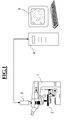
- the system shown in Figure 1 consists of a microscope (1) with a motor-adjustable preparation table (2), a video camera (3) and one Image processing computer (4) with a monitor (5) connected to it Image is used.
- Color images are generated without additional interpolation using the color co-site method with a color mask corresponding to FIG. 2a.
- R, G and B indicate the red, green and blue sensitive color pixels.
- the so-called “microscanning” method is used to increase the density of the image scan and thus the resolution of the image system.
- the relative displacement of the CCD sensor and the beam path of the microscopic image that is to say a displacement of the depicted object details relative to the sensor surface of the CCD sensor between the partial images, results in multiple scanning of the object.
- the high-resolution overlay image P (x, y) from m r xn r individual images P t (x, y), the lateral resolution in the composite image corresponding to mr or n r times the lateral resolution of the individual images.
- the Grid represents the scanning grid placed over the image.
- the reinforced leg denotes a corner of the CCD array with the red-sensitive CCD cell arranged there.
- the array is relative to a grid of the scanning grid in 6x6 steps shifted to the image and in 36 individual data records, each of which is a drawing file, read.
- the object details may be relative to each other during the Do not move the entire recording time of the series of drawing files.
- the inventive method for compensating for the differences in intensity decaying fluorescence is the representation of an artifact-free fluorescence image in high image quality possible.
- the intensity values of the individual drawing files (P1, P2, ... Pn) before or after nesting with Gain factors (V) multiplied are shown in FIG. 3, the intensity values of the individual drawing files (P1, P2, ... Pn) before or after nesting with Gain factors (V) multiplied.
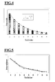
- the intensity of the light emitted is proportional to the amount of the fluorophore concentration. Since the number of luminous elements generally decreases in accordance with an exponential function, the intensity of the image also decreases in accordance with an exponential function. This is shown for example in FIG. 4 for nine partial images.
- the half-lives or the attenuation constant 1 / t 0 for various active substances, also called markers, are generally known or can be determined by measurement.
- the method can be approximately determined from the measured data of the partial images. Examples for this are:
- the intensity of an image can be determined as the mean over all n pixels
- the intensity for the individual color channels R (k, l), G (k, l) and B (k, l) and pixels (k, l) can be determined accordingly
- the quotients from the intensity of a color channel at time t and the initial intensity of the color channel at time t 0 can be summed and the gain factor can be formed from the sum
- the Gain factor determined with a higher statistical certainty.
- the intensity In the case of fluorescent objects, the intensity essentially weakens over time within the object itself.
- the intensity of the background remains relatively constant.
- Global artifacts with a uniform amplification factor for the entire image can be used to generate new artifacts in the image background, since the intensity of the image background is also used to determine the attenuation and the amplification factor.
- a further improvement in compensation can be achieved if the fluorescent objects are segmented in a partial image in an upstream segmentation step (6), see FIG. 7, and a mask of the segmented image areas is formed in a subsequent masking step (7).
- the segmentation can be carried out, for example, by a simple threshold value query.
- a simple threshold value query In Usually, however, one will use procedures using local means and use local variance. Such methods are described, for example, in Bernd Jähne, et. al .: Handbook of Computer Vision and Applications, 1999, Academic Press, London described. A particularly high level of certainty in determining the object boundaries can be achieved with the methods proposed in DE 10017551.1.
- the segmentation can be carried out for each measured partial image. However, it is sufficient to carry out a segmentation only on the basis of the first partial image and to generate an object mask M (k, l) for identifying the objects and to use them for all further evaluations and calculations of the amplification factors.
- the compensation can also be limited to the segmented objects. However, in order to avoid additional artifacts at the object boundaries, it is advantageous to insert a transition region along the object edges, in which the gain increases from 1 to V t , as is shown in FIG. 7.
- the object mask M (k, l) is converted into the amplification matrix M t (k, l). You get for the compensated drawing file
- the symbol ° is used here for a multiplication of the individual elements of the matrices or the image
- the method can also be extended to simultaneous multichannel fluorescence. If you excite the object with up to three markers that emit light in different wavelengths, it is possible to differentiate and automatically separate a maximum of three fluorescence channels. However, the prerequisite for this is that several emission signals do not fall exclusively or predominantly into one color channel. In other words, with three different markers, the emission focus should be distributed over all three color channels if possible. It is also assumed that the spectral sensitivity curves of the individual color channels as a function of the wavelength are known. In Figure 8, the spectral sensitivity curves of the individual color channels - blue, green, red - of a recording system are shown schematically.
- the signals S 1 to S 3 shown in the diagram for example the fluorescence lines of three markers 1, 2, 3, contribute to the color channels with the transmission coefficients T xn .
- X denotes the color channel R, G, B and n the number of the signal or marker.
- S 1 , S 2 , S 3 and R, G, B are functions of (k, l)
- the color image can thus be separated into the images of the three emitting signals. Gray values or false colors can then be assigned to the individual signals. It it should be pointed out again that for a good separation of the signals the individual Signals should not be too close in frequency and individual transmission coefficients should not become arbitrarily small. The equations can be used for two Simplify different markers accordingly.
- the partial images measured at different times are each according to Eq. (13) into the signals S 1t , S 2t , S 3t .
- the compensation of the individual signals is then calculated separately for each fluorescent signal in accordance with the above-mentioned methods.
- the methods for determining the amplification factors are accordingly applied to the individual signals or their images.
Landscapes
- Engineering & Computer Science (AREA)
- Multimedia (AREA)
- Physics & Mathematics (AREA)
- General Physics & Mathematics (AREA)
- Analytical Chemistry (AREA)
- Theoretical Computer Science (AREA)
- Computer Vision & Pattern Recognition (AREA)
- Chemical & Material Sciences (AREA)
- Signal Processing (AREA)
- Optics & Photonics (AREA)
- Image Processing (AREA)
- Investigating, Analyzing Materials By Fluorescence Or Luminescence (AREA)
- Color Television Image Signal Generators (AREA)
- Facsimile Image Signal Circuits (AREA)
- Microscoopes, Condenser (AREA)
- Studio Circuits (AREA)
Abstract
Description
- Figur 1:
- ein Mikroskop mit Kamera und Rechnersystem zur Ausführung der Erfindung in der Fluoreszenzmikroskopie;
- Figur 2a:
- eine schematische Darstellung von CCD-Arrays mit einer Anordnung der Farbmaske und dem Laufweg zur Aufnahme von Teilbildern,
- Figur 2b:
- eine schematische Darstellung der Abtastung im Co-Site-Sampling-Verfahren mit zusätzlich dreifacher Auflösung,
- Figur 3:
- ein Blockschaltbild für die Verschachtelung von Teilbildern;
- Figur 4 :
- ein Diagramm des Abfalls der Intensität während eines Microscanns;
- Figur 5:
- ein Diagramm für die Approximation der gemessenen Intensitäten durch eine Exponentialfunktion;
- Figur 6:
- ein Blockschaltbild einer erweiterten Fading-Kompensation;
- Figur 7:
- Segmentierte Bildbereiche;
- Figur 8:
- Selektionskurven der Farbkanäle, und
- Figur 9:
- ein Blockschaltbild eine Ausschnitts eines Rechenwerkes zur Kanaltrennung








Claims (19)
- Verfahren zur Aufzeichnung und Darstellung von Fluoreszenzbildern mit hoher räumlicher Auflösung, bei dem mehrere Aufnahmen eines Bildes eines Objektes zeitlich sequentiell mit einer elektronischen Kamera aufgenommen werden und zwischen den Aufnahmen laterale Verschiebungen zwischen dem Bild des Objektes und der elektronischen Kamera vorgenommen werden, und wobei die Aufnahmen zu einem zusammengesetzten Bild höherer räumlicher Auflösung vereinigt werden, dadurch gekennzeichnet, daß die zu Bildpunkten der Bilder gehörigen Signale, die zu unterschiedlichen Zeiten gewonnen werden, mit Verstärkungsfaktoren verstärkt werden, die von den Zeitabständen zwischen den betreffenden Bildaufnahmen abhängen.
- Verfahren nach Anspruch 1, wobei die Zeitabhängigkeit der Verstärkungsfaktoren im wesentlichen reziprok zu der Zeitabhängigkeit der Intensität der Fluoreszenz ist.
- Verfahren nach Anspruch 1 oder 2, wobei die Verstärkung der Signale vor der Vereinigung der zeitlich sequentiell aufgenommenen Aufnahmen erfolgt.
- Verfahren nach Anspruch 1 oder 2, wobei die zeitlich sequentiell aufgenommenen Aufnahmen zunächst zu einem Gesamtbild höherer Auflösung zusammengesetzt werden und nachfolgend die zu den Bildpunkten des zusammen gesetzten Bildes gehörigen Signale verstärkt werden.
- Verfahren nach einem der Ansprüche 1 bis 4, wobei die Verstärkungsfaktoren durch Mittelung der Signale in den einzelnen sequentiell aufgezeichneten Aufnahmen bestimmt werden.
- Verfahren nach einem der Ansprüche 1 bis 4, wobei die Verstärkungsfaktoren durch Mittelung der Signale in Teilbereichen der einzelnen sequentiell aufgezeichneten Aufnahmen bestimmt werden.
- Verfahren nach einem der Ansprüche 1 bis 4, wobei die Verstärkungsfaktoren für die einzelnen sequentiell aufgenommenen Aufnahmen durch Approximation eines an das natürliche zeitliche Abschwächungsverhalten angenäherten Verlaufs der Intensität der zur Fluoreszenz angeregten Stoffe bestimmt werden.
- Verfahren nach einem der Ansprüche 1 bis 7, wobei eine adaptive Bildfilterung des zusammengesetzten Bildes zur Unterdrückung von Rauschen erfolgt.
- Verfahren nach Anspruch 6, wobei die einzelnen seitlich sequentiell aufgenommenen Aufnahmen in Bildbereiche segmentiert werden und die Signale, die zu Bildpunkten unterschiedlicher Bildbereiche gehören, mit unterschiedlichen Verstärkungsfaktoren verstärkt, und die Signale, die zu Bildpunkten des selben Bildbereiches gehören, mit identischen Verstärkungsfaktoren verstärkt werden.
- Verfahren nach einem der Ansprüche 1 bis 9, wobei für die Bildaufnahmen eine Farb-CCD-Kamera eingesetzt wird.
- Verfahren nach Anspruch 10, wobei die Verschiebung zwischen dem Bild und der Kamera derart erfolgt, daß ein und der selbe Punkt des Objektes zeitlich sequentiell auf unterschiedliche Farbkanäle des selben CCD-Pixels der Kamera abgebildet wird.
- Verfahren nach Anspruch 11, wobei für die verschiedenen Farbkanäle unterschiedliche Verstärkungsfaktoren verwendet werden.
- Verfahren nach Anspruch 10, bei dem gleichzeitig mehrere Fluoreszenz-Emissionen angeregt werden und unterschiedliche Verstärkungsfaktoren für die einzelnen Emissionen unter Berücksichtigung der spektralen Empfindlichkeitskurven der Farbkanäle ermittelt werden.
- Verfahren nach Anspruch 13, bei dem die Ermittlung der Verstärkungsfaktoren für die einzelnen Emissionen durch Lösen eines linearen Gleichungssystems erfolgt.
- Verfahren nach Anspruch 13, bei dem die Ermittlung der Verstärkungsfaktoren für die einzelnen Emissionen durch ein Verfahren der Fuzzy Logig oder ein Verfahren der Neuro-Fuzzy-Logig erfolgt.
- Verfahren nach einem der Ansprüche 13 - 15, bei dem die einzelnen Emissionen als Falschfarben dargestellt werden.
- Fluoreszenzmikroskop mit einem optischen Beleuchtungssystem, einem optischen Abbildungssystem, einem Bildaufnahmesystem und einem Rechnersystem, wobei das Rechnersystem zum Ausführen eines Verfahrens nach einem der Ansprüche 1 bis 16 ausgebildet ist.
- Computersystem, das zur Ausführung eines Verfahrens nach einem der Ansprüche 1 bis 16 geeignet ist.
- Computerprogrammprodukt, das in den Speicher eines digitalen Computers ladbar ist und einen Softwarecode zur Durchführung eines Verfahrens mit den Schritten nach einem der Ansprüche 1 bis 16 aufweist, wenn das Programm auf dem Computer abläuft.
Applications Claiming Priority (2)
| Application Number | Priority Date | Filing Date | Title |
|---|---|---|---|
| DE10109130 | 2001-02-24 | ||
| DE2001109130 DE10109130B4 (de) | 2001-02-24 | 2001-02-24 | Verfahren zur Aufzeichnung und Darstellung von Fluoreszenzbildern mit hoher räumlicher Auflösung |
Publications (2)
| Publication Number | Publication Date |
|---|---|
| EP1235424A2 true EP1235424A2 (de) | 2002-08-28 |
| EP1235424A3 EP1235424A3 (de) | 2009-09-02 |
Family
ID=7675482
Family Applications (1)
| Application Number | Title | Priority Date | Filing Date |
|---|---|---|---|
| EP01128671A Withdrawn EP1235424A3 (de) | 2001-02-24 | 2001-12-01 | Verfahren zur Aufzeichnung und Darstellung von Fluoreszenzbildern mit hoher räumlicher Auflösung |
Country Status (3)
| Country | Link |
|---|---|
| US (1) | US7113205B2 (de) |
| EP (1) | EP1235424A3 (de) |
| DE (1) | DE10109130B4 (de) |
Cited By (5)
| Publication number | Priority date | Publication date | Assignee | Title |
|---|---|---|---|---|
| WO2004038483A1 (de) * | 2002-10-28 | 2004-05-06 | Carl Zeiss Jena Gmbh | Verfahren zur berbesserung der tiefendiskriminierung optisch abbildender systeme |
| WO2011036650A3 (en) * | 2009-09-28 | 2011-08-11 | Koninklijke Philips Electronics N.V. | Sensor device with imaging optics |
| DE102012107191A1 (de) | 2012-08-06 | 2014-02-06 | Jenoptik Optical Systems Gmbh | Verfahren zur hochauflösenden digitalen Farbbildaufnahme mit hohem Dynamikbereich |
| CN108492254A (zh) * | 2018-03-27 | 2018-09-04 | 西安优艾智合机器人科技有限公司 | 图像采集系统及方法 |
| CN113039428A (zh) * | 2019-04-02 | 2021-06-25 | 贝克顿·迪金森公司 | 补偿编辑器 |
Families Citing this family (12)
| Publication number | Priority date | Publication date | Assignee | Title |
|---|---|---|---|---|
| DE102005048006A1 (de) | 2005-10-06 | 2007-04-12 | Carl Zeiss Surgical Gmbh | Mikroskopiesystem und Aufnahmeverfahren zur Sichtbarmachung einer Fluoreszenz |
| EP2156370B1 (de) | 2007-05-14 | 2011-10-12 | Historx, Inc. | Abteilungsauftrennung durch pixelcharakterisierung unter verwendung von bilddatenclusterung |
| EP2162728B1 (de) * | 2007-06-15 | 2016-07-27 | Novartis AG | Mikroskopisches system und verfahren zur erfassung von standardisierten daten |
| CA2604317C (en) | 2007-08-06 | 2017-02-28 | Historx, Inc. | Methods and system for validating sample images for quantitative immunoassays |
| CA2596204C (en) | 2007-08-07 | 2019-02-26 | Historx, Inc. | Method and system for determining an optimal dilution of a reagent |
| WO2009029810A1 (en) | 2007-08-31 | 2009-03-05 | Historx, Inc. | Automatic exposure time selection for imaging tissue |
| WO2010033508A1 (en) | 2008-09-16 | 2010-03-25 | Historx, Inc. | Reproducible quantification of biomarker expression |
| JP2010191377A (ja) * | 2009-02-20 | 2010-09-02 | Olympus Corp | 顕微鏡撮像システム及び該動作方法 |
| JP5466876B2 (ja) * | 2009-05-14 | 2014-04-09 | オリンパス株式会社 | 画像取得装置、画像取得装置の制御方法、及び顕微鏡システム |
| DE102010063959A1 (de) * | 2010-12-22 | 2012-06-28 | Carl Zeiss Microlmaging Gmbh | Mikroskop mit einem Farbbildsensor sowie Mikroskopieverfahren mit einem Farbbildsensor |
| DE102014214750B3 (de) * | 2014-07-28 | 2015-06-11 | Reimar Lenz | Bildaufnahmesystem mit schnell vibrierendem Global-Shutter-CMOS-Sensor |
| DE102022115989A1 (de) | 2022-06-27 | 2023-12-28 | Carl Zeiss Microscopy Gmbh | Mikroskopiesystem und Verfahren zur Farbkorrektur von Mikroskopbildern |
Citations (1)
| Publication number | Priority date | Publication date | Assignee | Title |
|---|---|---|---|---|
| DE3837063C1 (de) * | 1988-10-31 | 1990-03-29 | Reimar Dr. 8000 Muenchen De Lenz |
Family Cites Families (15)
| Publication number | Priority date | Publication date | Assignee | Title |
|---|---|---|---|---|
| US4673988A (en) * | 1985-04-22 | 1987-06-16 | E.I. Du Pont De Nemours And Company | Electronic mosaic imaging process |
| JP3137632B2 (ja) * | 1989-08-31 | 2001-02-26 | 富士通株式会社 | 光ファイバ増幅器を備えた光通信方式 |
| JPH04326316A (ja) * | 1991-04-26 | 1992-11-16 | Olympus Optical Co Ltd | 顕微鏡用写真撮影装置 |
| DE4230724C1 (de) * | 1992-09-14 | 1993-10-14 | Leica Mikroskopie & Syst | Verfahren und Vorrichtung zur Belichtungssteuerung für die Fluoreszenzmikrofotografie |
| DE19532897A1 (de) | 1994-09-27 | 1996-03-28 | Zeiss Carl Fa | Verfahren zur Belichtungssteuerung bei Mikroskopkameras und entsprechendes Photomikroskop |
| US5866331A (en) * | 1995-10-20 | 1999-02-02 | University Of Massachusetts | Single molecule detection by in situ hybridization |
| US5798801A (en) * | 1996-05-08 | 1998-08-25 | U.S. Philips Corporation | Arrangement for providing vivid color in a television signal |
| WO1998017992A2 (en) * | 1996-10-25 | 1998-04-30 | Applied Imaging, Inc. | Multifluor-fluorescence in situ hybridization (m-fish) imaging techniques using multiple multiband filters with image registration |
| JP3583618B2 (ja) * | 1998-06-15 | 2004-11-04 | 富士通株式会社 | 画像処理装置、画像処理方法およびその方法をコンピュータに実行させるプログラムを記録したコンピュータ読み取り可能な記録媒体 |
| JP3892172B2 (ja) * | 1998-07-24 | 2007-03-14 | 松下電器産業株式会社 | 固体撮像装置 |
| JP3375557B2 (ja) * | 1999-01-29 | 2003-02-10 | 松下電器産業株式会社 | 映像信号処理装置 |
| US6650779B2 (en) * | 1999-03-26 | 2003-11-18 | Georgia Tech Research Corp. | Method and apparatus for analyzing an image to detect and identify patterns |
| IL133243A0 (en) * | 1999-03-30 | 2001-03-19 | Univ Ramot | A method and system for super resolution |
| DE10017551C2 (de) | 2000-04-08 | 2002-10-24 | Carl Zeiss Vision Gmbh | Verfahren zur zyklischen, interaktiven Bildanalyse sowie Computersystem und Computerprogramm zur Ausführung des Verfahrens |
| US7440637B2 (en) * | 2000-07-21 | 2008-10-21 | The Trustees Of Columbia University In The City Of New York | Method and apparatus for image mosaicing |
-
2001
- 2001-02-24 DE DE2001109130 patent/DE10109130B4/de not_active Expired - Fee Related
- 2001-12-01 EP EP01128671A patent/EP1235424A3/de not_active Withdrawn
-
2002
- 2002-02-21 US US10/078,688 patent/US7113205B2/en not_active Expired - Lifetime
Patent Citations (1)
| Publication number | Priority date | Publication date | Assignee | Title |
|---|---|---|---|---|
| DE3837063C1 (de) * | 1988-10-31 | 1990-03-29 | Reimar Dr. 8000 Muenchen De Lenz |
Non-Patent Citations (2)
| Title |
|---|
| BÖCKER W ET AL: "Automated cell cycle analysis with fluorescence microscopy and image analysis", PHYSICS IN MEDICINE AND BIOLOGY, INSTITUTE OF PHYSICS PUBLISHING, BRISTOL GB, vol. 41, 1 January 1996 (1996-01-01), pages 523 - 527, XP002257574, ISSN: 0031-9155, DOI: 10.1088/0031-9155/41/3/013 * |
| ROST F W D ED - ROST ET AL: "Quantitative fluorescence microscopy passage", 1 March 1991, QUANTITATIVE FLUORESCENCE MICROSCOPY, CAMBRIDGE UNIVERSITY PRESS, GB, PAGE(S) 10, ISBN: 978-0-521-39422-2, XP002537533 * |
Cited By (9)
| Publication number | Priority date | Publication date | Assignee | Title |
|---|---|---|---|---|
| WO2004038483A1 (de) * | 2002-10-28 | 2004-05-06 | Carl Zeiss Jena Gmbh | Verfahren zur berbesserung der tiefendiskriminierung optisch abbildender systeme |
| US7335866B2 (en) | 2002-10-28 | 2008-02-26 | Carl Zeiss Microimaging Gmbh | Method for improving depth discrimination in optical reproduction systems |
| WO2011036650A3 (en) * | 2009-09-28 | 2011-08-11 | Koninklijke Philips Electronics N.V. | Sensor device with imaging optics |
| CN102713571A (zh) * | 2009-09-28 | 2012-10-03 | 皇家飞利浦电子股份有限公司 | 具有成像光学元件的传感器设备 |
| US9250181B2 (en) | 2009-09-28 | 2016-02-02 | Koninklijke Philips N.V. | Sensor device with imaging optics |
| DE102012107191A1 (de) | 2012-08-06 | 2014-02-06 | Jenoptik Optical Systems Gmbh | Verfahren zur hochauflösenden digitalen Farbbildaufnahme mit hohem Dynamikbereich |
| CN108492254A (zh) * | 2018-03-27 | 2018-09-04 | 西安优艾智合机器人科技有限公司 | 图像采集系统及方法 |
| CN113039428A (zh) * | 2019-04-02 | 2021-06-25 | 贝克顿·迪金森公司 | 补偿编辑器 |
| CN113039428B (zh) * | 2019-04-02 | 2025-05-16 | 贝克顿·迪金森公司 | 补偿编辑器 |
Also Published As
| Publication number | Publication date |
|---|---|
| DE10109130A1 (de) | 2002-09-05 |
| US20020176007A1 (en) | 2002-11-28 |
| DE10109130B4 (de) | 2015-02-19 |
| EP1235424A3 (de) | 2009-09-02 |
| US7113205B2 (en) | 2006-09-26 |
Similar Documents
| Publication | Publication Date | Title |
|---|---|---|
| DE3910035C2 (de) | ||
| DE10109130B4 (de) | Verfahren zur Aufzeichnung und Darstellung von Fluoreszenzbildern mit hoher räumlicher Auflösung | |
| DE69022584T2 (de) | Methode zum ableiten von rauschreduzierschätzungen von farbsignalparametern von mehreren farb/helligkeit-bildsensorausgängen. | |
| DE102006011707B4 (de) | Verfahren und Vorrichtung zum Erzeugen einer strukturfreien fiberskopischen Aufnahme | |
| DE2952422C3 (de) | Verfahren und Vorrichtung zum Verarbeiten eines Röntgenbildes bei einem Röntgenbild-Kopiersystem | |
| DE69733882T2 (de) | Kamera mit einem einzigen bildaufnehmer | |
| DE69429068T2 (de) | Verfahren zur Reduzierung von Farbübersprechen | |
| DE3588169T2 (de) | Verfahren zur Detektion einer Bildbelichtungsfläche in einem Bildauslesevorgang | |
| DE60133160T2 (de) | Digitalbild-Verarbeitungsverfahren und Vorrichtung zur Helligkeitseinstellung von Digitalbildern | |
| DE69032834T2 (de) | Verfahren und Apparat für Farbbildsignalbewertung | |
| DE19616440A1 (de) | Verfahren und Vorrichtung zur Gewinnung eines vollen Farbbildes oder Multispektralbildes aus Bilddaten eines CCD-Bildsensors mit Mosaik-Farbfilter | |
| DE112012004493B4 (de) | Steuerungsverfahren für die Farbbeleuchtung zur Verbesserung der Bildqualität in einembildgebenden System | |
| DE3732435C2 (de) | ||
| DE69523043T2 (de) | Zusammenstellung eines bildes aus teilbildern | |
| DE4006592A1 (de) | Automatische fokussiervorrichtung | |
| DE69612463T2 (de) | Erstellung eines bildes aus teilbildern | |
| DE3931934A1 (de) | Bild-ein-/ausgabevorrichtung | |
| DE69927239T2 (de) | System und verfahren zur verarbeitung von bildern | |
| DE112016001559T5 (de) | Abbildungssystem, das strukturiertes Licht zur Tiefenrückgewinnung nutzt | |
| DE112014006672T5 (de) | Bildverarbeitungsvorrichtung, Bildgebungsvorrichtung, Mikroskopsystem, Bildverarbeitungsverfahren und ein Bildverarbeitungsprogramm | |
| EP3635677A1 (de) | Verfahren und vorrichtung zur bildkorrektur | |
| DE102017117428B4 (de) | Bildgebendes Verfahren unter Ausnutzung von Fluoreszenz sowie zugehörige Bildaufnahmevorrichtung | |
| DE112017004403T5 (de) | Endoskopsystem und charakteristischer betrag-berechnungsverfahren | |
| DE102008015979A1 (de) | Bewegt-Bild-Verarbeitungssystem und Bewegt-Bild-Verarbeitungsverfahren | |
| DE102007014413A1 (de) | Verfahren und Vorrichtung zum Auswerten von Fluoreszenzbildern |
Legal Events
| Date | Code | Title | Description |
|---|---|---|---|
| PUAI | Public reference made under article 153(3) epc to a published international application that has entered the european phase |
Free format text: ORIGINAL CODE: 0009012 |
|
| AK | Designated contracting states |
Kind code of ref document: A2 Designated state(s): AT BE CH CY DE DK ES FI FR GB GR IE IT LI LU MC NL PT SE TR |
|
| AX | Request for extension of the european patent |
Free format text: AL;LT;LV;MK;RO;SI |
|
| RAP1 | Party data changed (applicant data changed or rights of an application transferred) |
Owner name: CARL ZEISS Owner name: CARL-ZEISS-STIFTUNG TRADING AS CARL ZEISS |
|
| PUAL | Search report despatched |
Free format text: ORIGINAL CODE: 0009013 |
|
| AK | Designated contracting states |
Kind code of ref document: A3 Designated state(s): AT BE CH CY DE DK ES FI FR GB GR IE IT LI LU MC NL PT SE TR |
|
| AX | Request for extension of the european patent |
Extension state: AL LT LV MK RO SI |
|
| 17P | Request for examination filed |
Effective date: 20091125 |
|
| 17Q | First examination report despatched |
Effective date: 20100112 |
|
| AKX | Designation fees paid |
Designated state(s): DE FR GB |
|
| RAP1 | Party data changed (applicant data changed or rights of an application transferred) |
Owner name: CARL-ZEISS-STIFTUNG TRADING AS CARL ZEISS Owner name: CARL ZEISS AG |
|
| RAP1 | Party data changed (applicant data changed or rights of an application transferred) |
Owner name: CARL ZEISS AG |
|
| RAP1 | Party data changed (applicant data changed or rights of an application transferred) |
Owner name: CARL ZEISS MICROSCOPY GMBH |
|
| STAA | Information on the status of an ep patent application or granted ep patent |
Free format text: STATUS: THE APPLICATION HAS BEEN WITHDRAWN |
|
| 18W | Application withdrawn |
Effective date: 20180423 |
|
| RIC1 | Information provided on ipc code assigned before grant |
Ipc: H04N 3/15 20060101AFI20020619BHEP Ipc: G02B 21/36 20060101ALI20020619BHEP |