EP1235424A2 - Method for recording and displaying fluorescence images with high resolution - Google Patents
Method for recording and displaying fluorescence images with high resolution Download PDFInfo
- Publication number
- EP1235424A2 EP1235424A2 EP01128671A EP01128671A EP1235424A2 EP 1235424 A2 EP1235424 A2 EP 1235424A2 EP 01128671 A EP01128671 A EP 01128671A EP 01128671 A EP01128671 A EP 01128671A EP 1235424 A2 EP1235424 A2 EP 1235424A2
- Authority
- EP
- European Patent Office
- Prior art keywords
- image
- recordings
- individual
- gain factors
- signals
- Prior art date
- Legal status (The legal status is an assumption and is not a legal conclusion. Google has not performed a legal analysis and makes no representation as to the accuracy of the status listed.)
- Withdrawn
Links
- 238000000034 method Methods 0.000 title claims abstract description 60
- 238000002073 fluorescence micrograph Methods 0.000 title claims description 7
- 238000004590 computer program Methods 0.000 claims abstract description 3
- 230000036961 partial effect Effects 0.000 claims description 29
- 230000003321 amplification Effects 0.000 claims description 22
- 238000003199 nucleic acid amplification method Methods 0.000 claims description 22
- 239000002131 composite material Substances 0.000 claims description 6
- 230000008569 process Effects 0.000 claims description 6
- 230000003044 adaptive effect Effects 0.000 claims description 5
- 230000003595 spectral effect Effects 0.000 claims description 5
- 230000003313 weakening effect Effects 0.000 claims description 5
- 238000012935 Averaging Methods 0.000 claims description 4
- 238000001914 filtration Methods 0.000 claims description 4
- 230000035945 sensitivity Effects 0.000 claims description 4
- 239000003086 colorant Substances 0.000 claims description 3
- 239000000126 substance Substances 0.000 claims description 3
- 230000003287 optical effect Effects 0.000 claims description 2
- 238000012634 optical imaging Methods 0.000 claims description 2
- 230000002123 temporal effect Effects 0.000 claims description 2
- 238000003384 imaging method Methods 0.000 claims 1
- 238000001454 recorded image Methods 0.000 claims 1
- 230000001419 dependent effect Effects 0.000 abstract description 3
- 238000006073 displacement reaction Methods 0.000 abstract description 3
- 238000005562 fading Methods 0.000 description 6
- 230000011218 segmentation Effects 0.000 description 6
- 238000010586 diagram Methods 0.000 description 5
- 239000011159 matrix material Substances 0.000 description 5
- 238000012545 processing Methods 0.000 description 5
- 230000006872 improvement Effects 0.000 description 4
- 238000005259 measurement Methods 0.000 description 4
- 238000000926 separation method Methods 0.000 description 4
- 238000003491 array Methods 0.000 description 3
- 230000005540 biological transmission Effects 0.000 description 3
- 238000004061 bleaching Methods 0.000 description 3
- 230000007423 decrease Effects 0.000 description 3
- 230000000694 effects Effects 0.000 description 3
- 238000002360 preparation method Methods 0.000 description 3
- 238000005070 sampling Methods 0.000 description 3
- 108010014172 Factor V Proteins 0.000 description 2
- 239000004480 active ingredient Substances 0.000 description 2
- 238000004364 calculation method Methods 0.000 description 2
- 238000012937 correction Methods 0.000 description 2
- 239000003550 marker Substances 0.000 description 2
- 239000000203 mixture Substances 0.000 description 2
- 108010076282 Factor IX Proteins 0.000 description 1
- 239000013543 active substance Substances 0.000 description 1
- 230000002238 attenuated effect Effects 0.000 description 1
- 230000008859 change Effects 0.000 description 1
- 230000003247 decreasing effect Effects 0.000 description 1
- 238000011156 evaluation Methods 0.000 description 1
- 230000005284 excitation Effects 0.000 description 1
- 238000000799 fluorescence microscopy Methods 0.000 description 1
- 238000005286 illumination Methods 0.000 description 1
- 230000002452 interceptive effect Effects 0.000 description 1
- 230000000873 masking effect Effects 0.000 description 1
- 238000000386 microscopy Methods 0.000 description 1
- BRJCLSQFZSHLRL-UHFFFAOYSA-N oregon green 488 Chemical compound OC(=O)C1=CC(C(=O)O)=CC=C1C1=C2C=C(F)C(=O)C=C2OC2=CC(O)=C(F)C=C21 BRJCLSQFZSHLRL-UHFFFAOYSA-N 0.000 description 1
- 230000002829 reductive effect Effects 0.000 description 1
- 230000007704 transition Effects 0.000 description 1
- 238000011144 upstream manufacturing Methods 0.000 description 1
Images


Classifications
-
- G—PHYSICS
- G02—OPTICS
- G02B—OPTICAL ELEMENTS, SYSTEMS OR APPARATUS
- G02B21/00—Microscopes
- G02B21/36—Microscopes arranged for photographic purposes or projection purposes or digital imaging or video purposes including associated control and data processing arrangements
- G02B21/365—Control or image processing arrangements for digital or video microscopes
- G02B21/367—Control or image processing arrangements for digital or video microscopes providing an output produced by processing a plurality of individual source images, e.g. image tiling, montage, composite images, depth sectioning, image comparison
-
- G—PHYSICS
- G06—COMPUTING; CALCULATING OR COUNTING
- G06T—IMAGE DATA PROCESSING OR GENERATION, IN GENERAL
- G06T3/00—Geometric image transformation in the plane of the image
- G06T3/40—Scaling the whole image or part thereof
-
- H—ELECTRICITY
- H01—ELECTRIC ELEMENTS
- H01L—SEMICONDUCTOR DEVICES NOT COVERED BY CLASS H10
- H01L27/00—Devices consisting of a plurality of semiconductor or other solid-state components formed in or on a common substrate
- H01L27/14—Devices consisting of a plurality of semiconductor or other solid-state components formed in or on a common substrate including semiconductor components sensitive to infrared radiation, light, electromagnetic radiation of shorter wavelength or corpuscular radiation and specially adapted either for the conversion of the energy of such radiation into electrical energy or for the control of electrical energy by such radiation
- H01L27/144—Devices controlled by radiation
- H01L27/146—Imager structures
- H01L27/14601—Structural or functional details thereof
- H01L27/14603—Special geometry or disposition of pixel-elements, address-lines or gate-electrodes
-
- H—ELECTRICITY
- H04—ELECTRIC COMMUNICATION TECHNIQUE
- H04N—PICTORIAL COMMUNICATION, e.g. TELEVISION
- H04N25/00—Circuitry of solid-state image sensors [SSIS]; Control thereof
- H04N25/48—Increasing resolution by shifting the sensor relative to the scene
Definitions
- An additional microscanning can scan an image in both Directions can be increased by up to a factor of three.
- the number of recorded pixels increased by up to a further factor nine.
- another Increasing the scanning does not make sense because of the finite finish.
- the "microscanning" technique for increasing the resolution requires that an image P be composed of a plurality of sub-images P n taken in succession.
- the method is therefore sensitive to movements of the object or changes in the luminosity.
- the stability of the brightness of the object is a problem when taking fluorescence images. Due to the fluorescence-stimulating illumination, the preparation undergoes bleaching, so-called “photo bleaching” and thus a decrease in the intensity of the fluorescence, so-called "fading".
- the composition of the partial images taken in succession then results in artifacts in the overall image which are caused by the different fluorescence intensities of the partial images recorded sequentially in time are caused.
- the aim of the present invention is to provide a method for recording and reproducing Specify fluorescence images with high spatial resolution, in which the occurrence of Fading artifacts is avoided.
- digital cameras are used to increase the spatial resolution used with which multiple scanning in the so-called microscanning process is carried out. This is done either by deflecting the camera sensor relative to the Image or by deflecting the beam path relative to the camera sensor Scanned image shifted. Those recorded sequentially in time Drawing files are in the camera or the connected image computer cached and then offset to an image with increased resolution.
- intensity compensation is carried out before or after Nesting of the measurement data carried out with the aim of brightness and To compensate for color differences in the individual partial images and their color channels so that a optimal compensation for the fluorescence recordings is created. For this, they become the intensity signals associated with individual pixels are amplified with amplification factors, which depend on the time intervals between the relevant image recordings.
- the time dependence of the gain factors is essentially reciprocal to that Time dependence of the intensity of the fluorescence.
- the amplification of the intensity signals associated with the individual pixels can take place before the merging of the recordings recorded sequentially in time.
- the recordings recorded sequentially in time are first put together to form an overall picture of higher resolution and below the signals belonging to the pixels of the composite image be reinforced.
- the gain factors can be sequenced by averaging the signals in each recorded recordings can be determined. However, it is advantageous if the Gain factors by averaging the signals in partial areas of the individual sequentially recorded recordings are made.
- the segmentation of the drawing files according to the fluorescent objects and the control of the amplification factors in Dependence on fluorescent objects and background provides another Improvement. The segmentation can be done by simple means Threshold query to differentiate between backlights and fluorescent Objects, but also using more complex processes such as in the DE 10017551.1. Another one is particularly useful when the signal-to-noise ratio is low Improvement achieved.
- the individual are sequentially laterally recorded recordings are segmented into image areas and the signals are too Pixels belong to different image areas, with different ones Gain factors are amplified, and the signals that go to pixels of the same Belong to the image area, are amplified with identical amplification factors.
- the use of the invention is particularly advantageous if as a digital camera for the A color CCD camera is used because then due to the relative long exposure times the bleaching effects are particularly strong.
- a Color camera is the shift between the image and the camera so that one and the same point of the object sequentially in time on different color channels of the same CCD pixel of the camera is imaged.
- the method according to the invention is also particularly advantageous in Multiple fluorescence can be used, if there are several in the preparation shown Different wavelengths of fluorescent substances are contained that pass through simultaneously the excitation light used is excited to fluorescence. It can different gain factors for the individual emissions below Taking into account the spectral sensitivity curves of the color channels of the camera be determined.
- the determination of the amplification factors for the individual emissions can be done by solving of a linear system of equations.
- the individual emissions can then be shown as false colors below.
- the invention is advantageous in connection with a fluorescence microscope optical lighting system, an optical imaging system, a Image recording system and a computer system can be used, the computer system for Execution of the relevant correction and superposition of the partial images is formed.
- the invention can be implemented in hardware or software in a computer his.
- the aim of the invention is to determine the amplification factors for the color channels of the individual Determine fields so that the intensity of the color channels across all fields after the Compensation is the same and therefore no interfering artifacts when nesting arise.
- invention is also applicable to grayscale images by using only one Channel is processed per drawing file.
- the system shown in Figure 1 consists of a microscope (1) with a motor-adjustable preparation table (2), a video camera (3) and one Image processing computer (4) with a monitor (5) connected to it Image is used.
- Color images are generated without additional interpolation using the color co-site method with a color mask corresponding to FIG. 2a.
- R, G and B indicate the red, green and blue sensitive color pixels.
- the so-called “microscanning” method is used to increase the density of the image scan and thus the resolution of the image system.
- the relative displacement of the CCD sensor and the beam path of the microscopic image that is to say a displacement of the depicted object details relative to the sensor surface of the CCD sensor between the partial images, results in multiple scanning of the object.
- the high-resolution overlay image P (x, y) from m r xn r individual images P t (x, y), the lateral resolution in the composite image corresponding to mr or n r times the lateral resolution of the individual images.
- the Grid represents the scanning grid placed over the image.
- the reinforced leg denotes a corner of the CCD array with the red-sensitive CCD cell arranged there.
- the array is relative to a grid of the scanning grid in 6x6 steps shifted to the image and in 36 individual data records, each of which is a drawing file, read.
- the object details may be relative to each other during the Do not move the entire recording time of the series of drawing files.
- the inventive method for compensating for the differences in intensity decaying fluorescence is the representation of an artifact-free fluorescence image in high image quality possible.
- the intensity values of the individual drawing files (P1, P2, ... Pn) before or after nesting with Gain factors (V) multiplied are shown in FIG. 3, the intensity values of the individual drawing files (P1, P2, ... Pn) before or after nesting with Gain factors (V) multiplied.
- the intensity of the light emitted is proportional to the amount of the fluorophore concentration. Since the number of luminous elements generally decreases in accordance with an exponential function, the intensity of the image also decreases in accordance with an exponential function. This is shown for example in FIG. 4 for nine partial images.
- the half-lives or the attenuation constant 1 / t 0 for various active substances, also called markers, are generally known or can be determined by measurement.
- the method can be approximately determined from the measured data of the partial images. Examples for this are:
- the intensity of an image can be determined as the mean over all n pixels
- the intensity for the individual color channels R (k, l), G (k, l) and B (k, l) and pixels (k, l) can be determined accordingly
- the quotients from the intensity of a color channel at time t and the initial intensity of the color channel at time t 0 can be summed and the gain factor can be formed from the sum
- the Gain factor determined with a higher statistical certainty.
- the intensity In the case of fluorescent objects, the intensity essentially weakens over time within the object itself.
- the intensity of the background remains relatively constant.
- Global artifacts with a uniform amplification factor for the entire image can be used to generate new artifacts in the image background, since the intensity of the image background is also used to determine the attenuation and the amplification factor.
- a further improvement in compensation can be achieved if the fluorescent objects are segmented in a partial image in an upstream segmentation step (6), see FIG. 7, and a mask of the segmented image areas is formed in a subsequent masking step (7).
- the segmentation can be carried out, for example, by a simple threshold value query.
- a simple threshold value query In Usually, however, one will use procedures using local means and use local variance. Such methods are described, for example, in Bernd Jähne, et. al .: Handbook of Computer Vision and Applications, 1999, Academic Press, London described. A particularly high level of certainty in determining the object boundaries can be achieved with the methods proposed in DE 10017551.1.
- the segmentation can be carried out for each measured partial image. However, it is sufficient to carry out a segmentation only on the basis of the first partial image and to generate an object mask M (k, l) for identifying the objects and to use them for all further evaluations and calculations of the amplification factors.
- the compensation can also be limited to the segmented objects. However, in order to avoid additional artifacts at the object boundaries, it is advantageous to insert a transition region along the object edges, in which the gain increases from 1 to V t , as is shown in FIG. 7.
- the object mask M (k, l) is converted into the amplification matrix M t (k, l). You get for the compensated drawing file
- the symbol ° is used here for a multiplication of the individual elements of the matrices or the image
- the method can also be extended to simultaneous multichannel fluorescence. If you excite the object with up to three markers that emit light in different wavelengths, it is possible to differentiate and automatically separate a maximum of three fluorescence channels. However, the prerequisite for this is that several emission signals do not fall exclusively or predominantly into one color channel. In other words, with three different markers, the emission focus should be distributed over all three color channels if possible. It is also assumed that the spectral sensitivity curves of the individual color channels as a function of the wavelength are known. In Figure 8, the spectral sensitivity curves of the individual color channels - blue, green, red - of a recording system are shown schematically.
- the signals S 1 to S 3 shown in the diagram for example the fluorescence lines of three markers 1, 2, 3, contribute to the color channels with the transmission coefficients T xn .
- X denotes the color channel R, G, B and n the number of the signal or marker.
- S 1 , S 2 , S 3 and R, G, B are functions of (k, l)
- the color image can thus be separated into the images of the three emitting signals. Gray values or false colors can then be assigned to the individual signals. It it should be pointed out again that for a good separation of the signals the individual Signals should not be too close in frequency and individual transmission coefficients should not become arbitrarily small. The equations can be used for two Simplify different markers accordingly.
- the partial images measured at different times are each according to Eq. (13) into the signals S 1t , S 2t , S 3t .
- the compensation of the individual signals is then calculated separately for each fluorescent signal in accordance with the above-mentioned methods.
- the methods for determining the amplification factors are accordingly applied to the individual signals or their images.
Abstract
Description
Die Aufnahme von Bildern, insbesondere Fluoreszenzbildern in der Mikroskopie erfolgt heute vielfach mittels digitaler Kameras wie CCD-Kameras. Dafür werden heute Kameras in unterschiedlicher Bauform und mit unterschiedlicher Aufnahmequalität verwendet. Bei der Auswahl einer Kamera stehen die Parameter Aufhahmezeit und Auflösung in der Regel einander gegenüber. Bei hoher Bildrate ist nur eine begrenzte Aufnahmequalität zu erreichen. Hochauflösende digitale Kameras, mit entsprechend höherer örtlicher Auflösung benötigen eine ausreichende Belichtungszeit zur Reduktion des Bildrauschens pro Bildpunkt. Weiter Unterschiede liegen in der Art der Farbaufnahme mit oder ohne Farbteilem und Farbfiltern im Lichtweg und somit sequentieller oder paralleler Aufnahme der Farbkanäle.Images, in particular fluorescence images, are recorded in microscopy today often using digital cameras such as CCD cameras. That's what cameras are for today used in different designs and with different recording quality. at When choosing a camera, the parameters recording time and resolution are usually available towards each other. If the frame rate is high, the recording quality is limited to reach. High-resolution digital cameras, with a correspondingly higher local resolution need a sufficient exposure time to reduce the image noise per Pixel. There are further differences in the type of color recording with or without Color dividers and color filters in the light path and thus sequential or parallel recording of the color channels.
Bei der parallelen Aufnahme von Farbbildern mit drei Farbkanälen eines 1-Chip-Sensors besteht das grundsätzliche Problem, daß die eigentlich vorhandene Auflösung des Sensors durch die aufgebrachte Farbmaske mindestens halbiert wird. Dabei befindet sich beispielsweise auf der einen Hälfte der lichtempfindlichen Elemente (Pixel) eine grüne Maske; die andere Hälfte wird zu gleichen Teilen zwischen rot und blau aufgeteilt. Entsprechend reduziert sich die verfügbare Ortsauflösung in den jeweiligen spektralen Kanälen. Um ein Farbbild mit der Basisauflösung des CCD-Sensors zu erzeugen, wird in der Regel bei derartigen Kameras eine mathematische Interpolation zwischen den gemessenen Bildpunkten angewendet.When recording color images in parallel with three color channels of a 1-chip sensor there is the fundamental problem that the actual resolution of the sensor is at least halved by the applied color mask. Is located for example, a green one half of the photosensitive elements (pixels) Mask; the other half is divided equally between red and blue. The available spatial resolution in the respective spectral range is reduced accordingly Channels. To generate a color image with the basic resolution of the CCD sensor, in usually with such cameras, a mathematical interpolation between the measured pixels applied.
Durch das in der DE 38 37 063 Cl beschriebene Verfahren, dem so genannten "Color-Co-Site-Sampling" Verfahren, gelingt es, den durch die Farbmaske bedingten Auflösungsverlust vollständig zu kompensieren. Dazu wird der CCD-Sensor durch eine hochpräzise Piezomechanik relativ zu dem aufzuzeichnenden Bild derart verschoben, daß nacheinander jeweils an unterschiedlicher Position komplette Teilbilder mit den drei Farbkanälen (R-G-B) aufgezeichnet werden. Durch anschließende Verschachtelung der zeitlich sequentiell aufgezeichneten Teilbilder wird dann ohne Interpolation ein Gesamtbild erstellt. Die Verschiebung erfolgt dabei abhängig von der Farbmaske so, daß ein und der selbe Punkt im Objekt nacheinander von den drei Farbkanälen (z.B. 2x grün, 1x rot und 1x blau) detektiert wird.Through the method described in DE 38 37 063 C1, the so-called "color co-site sampling" Procedure, it succeeds the one caused by the color mask Compensate for loss of resolution completely. To do this, the CCD sensor is replaced by a high-precision piezo mechanics shifted relative to the image to be recorded such that complete drawing files with the three at different positions one after the other Color channels (R-G-B) are recorded. By then nesting the Sub-images recorded sequentially in time then become an overall image without interpolation created. The shift takes place depending on the color mask so that one and the same point in the object in succession from the three color channels (e.g. 2x green, 1x red and 1x blue) is detected.
Durch ein zusätzliches Microscanning kann die Abtastung eines Bildes in beiden Richtungen um bis zu einem Faktor drei erhöht werden. Entsprechend wird die Anzahl der aufgenommenen Bildpunkte um bis zu einem weiteren Faktor neun gesteigert. eine weitere Steigerung der Abtastung ist wegen der endlichen Appretur nicht sinnvoll.An additional microscanning can scan an image in both Directions can be increased by up to a factor of three. The number of recorded pixels increased by up to a further factor nine. another Increasing the scanning does not make sense because of the finite finish.
Die "Microscanning"-Technik zur Steigerung der Auflösung bedingt jedoch , daß ein Bild P aus mehreren nacheinander aufgenommenen Teilbildern Pn zusammengesetzt wird. Somit ist das Verfahren gegenüber Bewegungen des Objekts oder Veränderungen der Leuchtkraft empfindlich. Bei der Aufnahme von Fluorszenzbildern ist die Stabilität der Helligkeit des Objekts ein Problem. Durch die die Fluoreszenz anregende Beleuchtung, erfährt das Präparat eine Ausbleichung, ein sogenanntes "Photo Bleaching" und somit eine Abnahme der Intensität der Fluoreszenz, ein sogenanntes "Fading. Durch die Zusammensetzung der nacheinander aufgenommenen Teilbilder treten dann Artefakte im Gesamtbild auf, die durch die unterschiedlichen Fluoreszenzintensitäten der zeitlich sequentiell aufgenommenen Teilbilder verursacht sind.However, the "microscanning" technique for increasing the resolution requires that an image P be composed of a plurality of sub-images P n taken in succession. The method is therefore sensitive to movements of the object or changes in the luminosity. The stability of the brightness of the object is a problem when taking fluorescence images. Due to the fluorescence-stimulating illumination, the preparation undergoes bleaching, so-called "photo bleaching" and thus a decrease in the intensity of the fluorescence, so-called "fading". The composition of the partial images taken in succession then results in artifacts in the overall image which are caused by the different fluorescence intensities of the partial images recorded sequentially in time are caused.
Zur Beseitigung von Fading-Artefakten bei der Zusammensetzung zeitlich sequentiell aufgenommener Teilbilder ist es aus der US-A US 5682 567 und US-A 5 682 567 bekannt, die von Bild zu Bild abnehmende Intensität der Fluoreszenz durch eine entsprechende Verlängerung der Aufnahmezeit zu kompensieren. Die dafür erforderliche Korrektur der Belichtungszeit wird dabei jeweils vor der Datenacquisition bestimmt. Die Artefakte im zusammengesetzten Bild werden jedoch nur dann vermieden, wenn die Fluoreszenzintensitäten tatsächlich dem Gesetz gehorcht, das der Berechnung der korrigierten Belichtungszeiten zu Grunde gelegt ist. To eliminate fading artifacts in the composition sequentially in time captured partial images it is known from US-A US 5682 567 and US-A 5 682 567, the intensity of the fluorescence decreasing from image to image by a corresponding one To compensate for the extension of the recording time. The necessary correction of the The exposure time is determined before the data acquisition. The artifacts in the composite image are only avoided if the Fluorescence intensities actually obeyed the law that computed the law corrected exposure times.
Ziel der vorliegenden Erfindung ist es, ein Verfahren zur Aufnahme und Wiedergabe von Fluoreszenzbildern mit hoher räumlicher Auflösung anzugeben, bei dem das Auftreten von Fading-Artefakten vermieden wird.The aim of the present invention is to provide a method for recording and reproducing Specify fluorescence images with high spatial resolution, in which the occurrence of Fading artifacts is avoided.
Dieses Ziel wird durch ein Verfahren mit den Merkmalen des Anspruches 1, ein
Fluoreszenzmikroskop mit den Merkmalen des Anspruches 17, ein Computersystem mit
den Merkmalen des Anspruches 18 und ein Computerprogramm mit den Merkmalen des
Anspruches 19 gelöst. Vorteilhafte Ausführungsformen der Erfindung ergeben sich aus den
Merkmalen der abhängigen Ansprüche.This aim is achieved by a method having the features of
Zur Steigerung der Ortsauflösung werden, wie oben beschrieben, digitale Kameras eingesetzt, mit denen im sogenannten Microscanning-Verfahren eine Mehrfachabtastung durchgeführt wird. Dabei wird entweder durch Ablenken des Kamera-Sensors relativ zum Bild oder durch Ablenken das Strahlengangs relative zum Kamera-Sensor eine Verschiebung des abgetasteten Bilds erreicht. Die zeitlich sequentiell aufgezeichneten Teilbilder werden in der Kamera oder dem angeschlossenen Bildrechner zwischengespeichert und anschließend zu einem Bild mit erhöhter Auflösung verrechnet.As described above, digital cameras are used to increase the spatial resolution used with which multiple scanning in the so-called microscanning process is carried out. This is done either by deflecting the camera sensor relative to the Image or by deflecting the beam path relative to the camera sensor Scanned image shifted. Those recorded sequentially in time Drawing files are in the camera or the connected image computer cached and then offset to an image with increased resolution.
Erfindungsgemäß wird die Durchführung eines Intensitätsausgleichs vor oder nach der Verschachtelung der Meßdaten durchgeführt, mit dem Ziel die Helligkeits- und Farbunterschiede der einzelnen Teilbilder und deren Farbkanäle so auszugleichen, daß eine optimale Kompensation für die Fluoreszenz-Aufnahmen entsteht. Dazu werden die zu den einzelnen Bildpunkten zugehörigen Intensitätssignale mit Verstärkungsfaktoren verstärkt, die von den Zeitabständen zwischen den betreffenden Bildaufnahmen abhängen.According to the invention, intensity compensation is carried out before or after Nesting of the measurement data carried out with the aim of brightness and To compensate for color differences in the individual partial images and their color channels so that a optimal compensation for the fluorescence recordings is created. For this, they become the intensity signals associated with individual pixels are amplified with amplification factors, which depend on the time intervals between the relevant image recordings.
Die Zeitabhängigkeit der Verstärkungsfaktoren ist dabei im wesentlichen reziprok zu der Zeitabhängigkeit der Intensität der Fluoreszenz.The time dependence of the gain factors is essentially reciprocal to that Time dependence of the intensity of the fluorescence.
Die Verstärkung der zu den einzelnen Bildpunkten gehörigen Intensitätssignale kann zeitlich vor der Vereinigung der zeitlich sequentiell aufgenommenen Aufnahmen erfolgen. Alternativ ist es möglich, daß die zeitlich sequentiell aufgenommenen Aufnahmen zunächst zu einem Gesamtbild höherer Auflösung zusammengesetzt werden und nachfolgend die zu den Bildpunkten des zusammen gesetzten Bildes gehörigen Signale verstärkt werden.The amplification of the intensity signals associated with the individual pixels can take place before the merging of the recordings recorded sequentially in time. Alternatively, it is possible for the recordings recorded sequentially in time are first put together to form an overall picture of higher resolution and below the signals belonging to the pixels of the composite image be reinforced.
Die Verstärkungsfaktoren können durch Mittelung der Signale in den einzelnen sequentiell aufgezeichneten Aufnahmen ermittelt werden. Vorteilhaft ist es jedoch, wenn die Verstärkungsfaktoren durch Mittelung der Signale in Teilbereichen der einzelnen sequentiell aufgezeichneten Aufnahmen erfolgt. Die Segmentierung der Teilbilder nach den fluoreszierenden Objekten und die Steuerung der Verstärkungsfaktoren in Abhängigkeit von fluoreszierenden Objekten und Hintergrund liefert eine weitere Verbesserung. Dabei kann die Segmentierung durch einfache Mittel einer Schwellenabfrage zur Unterscheidung von Hintergrundleuchten und fluoreszierenden Objekten erfolgen, aber auch nach aufwendigeren Verfahren wie z.B. in der DE 10017551.1 beschrieben. Besonders bei niedrigem Rauschabstand wird eine weitere Verbesserung erzielt.The gain factors can be sequenced by averaging the signals in each recorded recordings can be determined. However, it is advantageous if the Gain factors by averaging the signals in partial areas of the individual sequentially recorded recordings are made. The segmentation of the drawing files according to the fluorescent objects and the control of the amplification factors in Dependence on fluorescent objects and background provides another Improvement. The segmentation can be done by simple means Threshold query to differentiate between backlights and fluorescent Objects, but also using more complex processes such as in the DE 10017551.1. Another one is particularly useful when the signal-to-noise ratio is low Improvement achieved.
Weiterhin ist es möglich, die Verstärkungsfaktoren für die einzelnen sequentiell aufgenommenen Aufnahmen durch Approximation eines an das natürliche zeitliche Abschwächungsverhalten angenäherten Verlaufs der Intensität der zur Fluoreszenz angeregten Stoffe zu ermitteln. Ist das Abklingverhalten der Fluoreszenz des verwendeten Wirkstoffs bekannt und erfolgt die Aufnahme der versetzten Teilbilder in einem festen Zeitraster Δt, so kann im idealen Fall, diese Vorschrift direkt für die Kompensation des Fading-Effekts und die Bestimmung der Verstärkungsfaktoren genutzt werden. In der Regel werden aber die Parameter der Abklingkurve Schwankungen von Probe zu Probe unterliegen. Eine weitere Verbesserung erhält man jedoch, wenn man die Kenntnis des grundsätzlichen Abklingverhaltens eines Wirkstoffs, z. B. entsprechend der Exponentialfunktion, zur Bestimmung der realen Abklingkurve verwendet und so den Einfluß der statistischen Schwankungen der Meßergebnisse mindert. Aus den mittleren Schwächungswerten der einzelnen Teilmessungen werden durch Approximation die Parameter der idealen Abklingkurve bestimmt.It is also possible to set the amplification factors for the individual sequentially Recorded recordings by approximating one to the natural temporal Attenuation behavior approximated the intensity of the fluorescence to determine excited substances. Is the decay behavior of the fluorescence used Known active ingredient and the recording of the offset partial images takes place in a fixed Time grid Δt, ideally, this rule can be used for the compensation of the Fading effect and the determination of the gain factors can be used. In the However, the parameters of the decay curve become fluctuations from sample to sample subject. A further improvement, however, can be obtained by knowing the basic decay behavior of an active ingredient, e.g. B. according to the Exponential function, used to determine the real decay curve and so the Influence of the statistical fluctuations of the measurement results. From the middle Attenuation values of the individual partial measurements are approximated Parameters of the ideal decay curve determined.
Bei einer vorteilhaften Ausführungsform werden die einzelnen seitlich sequentiell aufgenommenen Aufnahmen in Bildbereiche segmentiert und die Signale, die zu Bildpunkten unterschiedlicher Bildbereiche gehören, mit unterschiedlichen Verstärkungsfaktoren verstärkt, und die Signale, die zu Bildpunkten des selben Bildbereiches gehören, mit identischen Verstärkungsfaktoren verstärkt werden.In an advantageous embodiment, the individual are sequentially laterally recorded recordings are segmented into image areas and the signals are too Pixels belong to different image areas, with different ones Gain factors are amplified, and the signals that go to pixels of the same Belong to the image area, are amplified with identical amplification factors.
Besonders vorteilhaft ist der Einsatz der Erfindung, wenn als Digitalkamera für die Bildaufnahmen eine Farb-CCD-Kamera eingesetzt wird, da dann aufgrund der relativ langen Belichtungszeiten die Ausbleicheffekte besonders stark sind. Bei Einsatz einer Farbkamera erfolgt dabei die Verschiebung zwischen dem Bild und der Kamera derart, daß ein und der selbe Punkt des Objektes zeitlich sequentiell auf unterschiedliche Farbkanäle des selben CCD-Pixels der Kamera abgebildet wird.The use of the invention is particularly advantageous if as a digital camera for the A color CCD camera is used because then due to the relative long exposure times the bleaching effects are particularly strong. When using a Color camera is the shift between the image and the camera so that one and the same point of the object sequentially in time on different color channels of the same CCD pixel of the camera is imaged.
Es kann zweckmäßig sein, für die verschiedenen Farbkanäle unterschiedliche Verstärkungsfaktoren anzuwenden.It may be appropriate to use different color channels Apply gain factors.
Das erfindungsgemäße Verfahren ist besonders vorteilhaft auch bei Mehrfachfluoreszenzen anwendbar, wenn also im abgebildeten Präparat mehrere bei unterschiedlichen Wellenlängen fluoreszierende Stoffe enthalten sind, die simultan durch das verwendete Anregungslicht zur Fluoreszenz angeregt werden. Es können unterschiedliche Verstärkungsfaktoren für die einzelnen Emissionen unter Berücksichtigung der spektralen Empfindlichkeitskurven der Farbkanäle der Kamera ermittelt werden.The method according to the invention is also particularly advantageous in Multiple fluorescence can be used, if there are several in the preparation shown Different wavelengths of fluorescent substances are contained that pass through simultaneously the excitation light used is excited to fluorescence. It can different gain factors for the individual emissions below Taking into account the spectral sensitivity curves of the color channels of the camera be determined.
Die Ermittlung der Verstärkungsfaktoren für die einzelnen Emissionen kann durch Lösen eines linearen Gleichungssystems erfolgen. Alternativ ist es möglich, für die Ermittlung der Verstärkungsfaktoren für die einzelnen Emissionen Verfahren der Fuzzy Logig oder Verfahren der Neuro-Fuzzy-Logig anzuwenden, also Verfahren, bei denen anstelle von festen Beziehungen in Form von Gleichungen unscharfe Beziehungen in Form von Relationen als Ermittlungskriterien zugrunde gelegt werden.The determination of the amplification factors for the individual emissions can be done by solving of a linear system of equations. Alternatively, it is possible for the determination the amplification factors for the individual emissions method of the Fuzzy Logig or Apply the procedure of neuro-fuzzy-logig, i.e. procedures in which instead of fixed relationships in the form of equations fuzzy relationships in the form of Relationships are used as the determination criteria.
Die einzelnen Emissionen können dann nachfolgend als Falschfarben dargestellt werden. The individual emissions can then be shown as false colors below.
Die Erfindung ist vorteilhaft in Verbindung mit einem Fluoreszenzmikroskop mit einem optischen Beleuchtungssystem, einem optischen Abbildungssystem, einem Bildaufnahmesystem und einem Rechnersystem einsetzbar, wobei das Rechnersystem zum Ausführen der betreffenden Korrektur und Überlagerung der Teilbilder ausgebildet ist.The invention is advantageous in connection with a fluorescence microscope optical lighting system, an optical imaging system, a Image recording system and a computer system can be used, the computer system for Execution of the relevant correction and superposition of the partial images is formed.
Die Erfindung kann hardwaremäßig oder softwaremäßig in einem Rechner implementiert sein.The invention can be implemented in hardware or software in a computer his.
Ziel der Erfindung ist es, die Verstärkungsfaktoren für die Farbkanäle der einzelnen Teilbilder so zu bestimmen, daß die Intensität der Farbkanäle über alle Teilbilder nach der Kompensation gleich ist und somit bei der Verschachtelung keine störenden Artefakte entstehen. Dabei ist die Art der Verschachtelung der R-G-B-Sensoren und die Reihenfolge mit der die einzelnen Teilbilder gewonnen werden von untergeordneter Bedeutung. Die Ertfindung ist jedoch auch bei Grauwertbildern anwendbar, indem entsprechend nur ein Kanal pro Teilbild verarbeitet wird.The aim of the invention is to determine the amplification factors for the color channels of the individual Determine fields so that the intensity of the color channels across all fields after the Compensation is the same and therefore no interfering artifacts when nesting arise. The type of nesting of the R-G-B sensors and the sequence with which the individual drawing files are of minor importance. The However, invention is also applicable to grayscale images by using only one Channel is processed per drawing file.
Wird das Verfahren auf bereits verschachtelte R-G-B-Bilder angewendet, ist jedoch in Kauf zu nehmen, daß bei gegebenen CCD-Arrays häufig jeweils 2 Bildpunkte im grünen Kanal bei der Verschachtelung überlagert werden und somit nicht mehr einzeln getrennt und korrigiert werden können.If the method is applied to already nested R-G-B images, it is in To buy that with given CCD arrays often 2 pixels in the green Channel are overlaid during nesting and are therefore no longer separated individually and can be corrected.
Die Kompensation des Intensitätsabfalls durch einfache Verstärkung führt in der Regel zu einer Anhebung des Bildrauschens. Es ist daher zweckmäßig, zusätzlich zum Ausgleich der Helligkeit der einzelnen Teilbildern eine Optimierung des Bildrauschens durchzuführen. Entsprechende Verfahren Verfahren zur adaptiven, rauschoptimierten Filterung sind aus der Literatur, z.B. aus William A. Pratt: Digital Image Processing, 1978, John Wiley & Sons Inc.], New York bekannt.The compensation of the drop in intensity by simple amplification usually leads to an increase in image noise. It is therefore appropriate, in addition to compensate for the Brightness of the individual partial images to optimize the image noise. Corresponding methods Methods for adaptive, noise-optimized filtering are out literature, e.g. from William A. Pratt: Digital Image Processing, 1978, John Wiley & Sons Inc.], New York.
Nachfolgend wird die Erfindung anhand der Figuren im Detail beschrieben; dabei zeigen:
- Figur 1:
- ein Mikroskop mit Kamera und Rechnersystem zur Ausführung der Erfindung in der Fluoreszenzmikroskopie;
- Figur 2a:
- eine schematische Darstellung von CCD-Arrays mit einer Anordnung der Farbmaske und dem Laufweg zur Aufnahme von Teilbildern,
- Figur 2b:
- eine schematische Darstellung der Abtastung im Co-Site-Sampling-Verfahren mit zusätzlich dreifacher Auflösung,
- Figur 3:
- ein Blockschaltbild für die Verschachtelung von Teilbildern;
- Figur 4 :
- ein Diagramm des Abfalls der Intensität während eines Microscanns;
- Figur 5:
- ein Diagramm für die Approximation der gemessenen Intensitäten durch eine Exponentialfunktion;
- Figur 6:
- ein Blockschaltbild einer erweiterten Fading-Kompensation;
- Figur 7:
- Segmentierte Bildbereiche;
- Figur 8:
- Selektionskurven der Farbkanäle, und
- Figur 9:
- ein Blockschaltbild eine Ausschnitts eines Rechenwerkes zur Kanaltrennung
- Figure 1:
- a microscope with camera and computer system for carrying out the invention in fluorescence microscopy;
- Figure 2a:
- 1 shows a schematic representation of CCD arrays with an arrangement of the color mask and the path for recording partial images,
- Figure 2b:
- 1 shows a schematic representation of the sampling in the co-site sampling method with an additional triple resolution,
- Figure 3:
- a block diagram for the nesting of fields;
- Figure 4:
- a graph of the drop in intensity during a microscan;
- Figure 5:
- a diagram for the approximation of the measured intensities by an exponential function;
- Figure 6:
- a block diagram of an extended fading compensation;
- Figure 7:
- Segmented image areas;
- Figure 8:
- Selection curves of the color channels, and
- Figure 9:
- a block diagram a section of an arithmetic unit for channel separation
Das in der Figur 1 dargestellte System besteht aus einem Mikroskop (1) mit einem motorisch verstellbaren Präparattisch (2), einer Videokamera (3) und einem Bildverarbeitungsrechner (4) mit einem daran angeschlossenen Monitor (5), der zur Bilddarstellung dient.The system shown in Figure 1 consists of a microscope (1) with a motor-adjustable preparation table (2), a video camera (3) and one Image processing computer (4) with a monitor (5) connected to it Image is used.
Die Erzeugung von Farbbildern ohne zusätzliche Interpolation erfolgt nach dem Color-Co-Site-Verfahren mit einer Farbmaske entsprechend Figur 2a. Dort sind mit R, G und B die rot-, grün- und blauempfindlichen Farbpixel angedeutet. Für das Color-Co-Site-Verfahren werden vier Einzelbilder benötigt, die durch eine Verschiebung des Aufnahmesystems relativ zum aufzunehmenden Bild - oder des aufzunehmenden Bildes relativ zum Aufnahmesystem - in vier nacheinander folgenden Schritten um jeweils einen Rasterpunkt in x - und y-Richtung, entsprechend dem Laufweg ― 1-2-3-4- aufgenommen werden. Daraus resultiert eine Vervielfachung um mc x nc = 2 x 2 = 4 Teilbilder.Color images are generated without additional interpolation using the color co-site method with a color mask corresponding to FIG. 2a. R, G and B indicate the red, green and blue sensitive color pixels. For the color-co-site process, four individual images are required, which are shifted in four consecutive steps by one grid point in the x - and y directions by moving the recording system relative to the image to be recorded - or the image to be recorded relative to the recording system. according to the route - 1-2-3-4-. This results in a multiplication by m c xn c = 2 x 2 = 4 fields.
Zur Aufnahme von mikroskopischen Bildern mit hoher Auflösung wird zusätzlich das sogenannte "Microscanning"-Verfahren zur Erhöhung der Dichte der Bildabtastung und damit der Auflösung des Bildsystems eingesetzt. Dabei wird durch die relative Versetzung von CCD-Sensor und Strahlengang der mikroskopischen Abbildung, also eine Versetzung der abgebildeten Objektdetails relativ zur Sensorfläche des CCD-Sensors zwischen den Teilbildern eine Mehrfachabtastung des Objekts erzielt. Allgemein erhält man aus mr x nr Einzelbildern Pt(x,y) das hochaufgelöste Überlagerungsbild P(x,y), wobei die laterale Auflösung im zusammengesetzten Bild dem mr- bzw. nr-fachen der lateralen Auflösung der Einzelbilder entspricht.In order to record microscopic images with high resolution, the so-called "microscanning" method is used to increase the density of the image scan and thus the resolution of the image system. The relative displacement of the CCD sensor and the beam path of the microscopic image, that is to say a displacement of the depicted object details relative to the sensor surface of the CCD sensor between the partial images, results in multiple scanning of the object. In general, one obtains the high-resolution overlay image P (x, y) from m r xn r individual images P t (x, y), the lateral resolution in the composite image corresponding to mr or n r times the lateral resolution of the individual images.
Zur Verdeutlichung ist ein möglicher Ablauf der Verschiebungen bei dreifacher Auflösung und gleichzeitiger Anwendung des Color-Co-Site-Verfahrens in Figur 2b dargestellt. Das Gitter stellt das über das Bild gelegte Abtastraster dar. Der verstärkt gezeichnete Schenkel bezeichnet eine Ecke des CCD-Arrays mit der dort angeordneten rot-empfindlichen CCD-Zelle. Das Array wird in 6x6 Schritten jeweils um ein Rasterfeld des Abtastrasters relativ zum Bild verschoben und in 36 einzelnen Datensätzen, die jedes ein Teilbild darstellen, ausgelesen. Um eine fehlerfreie Überlagerung der zeitlich nacheinander gewonnenen Teilbilder zu erhalten, dürfen sich die Objektdetails relativ zueinander während der gesamten Aufhahmezeit der Serie der Teilbilder nicht bewegen.To illustrate this is a possible sequence of the shifts with triple resolution and simultaneous use of the color co-site method shown in Figure 2b. The Grid represents the scanning grid placed over the image. The reinforced leg denotes a corner of the CCD array with the red-sensitive CCD cell arranged there. The array is relative to a grid of the scanning grid in 6x6 steps shifted to the image and in 36 individual data records, each of which is a drawing file, read. To ensure an error-free overlay of the successively obtained To obtain drawing files, the object details may be relative to each other during the Do not move the entire recording time of the series of drawing files.
Eine Veränderung der Intensität ergibt sich aber zwangsläufig bei der Aufnahme von Fluoreszenz-Bildern. Die Leuchtkraft der emittierenden Bereiche bleicht mit der Zeit aus. So wird zum Beispiel bei der Aufnahme von mit dem Marker "Oregon Green 488" angeregten Zellen , die Intensität der Fluoreszenz in der Aufnahmezeit von 20 sec um 50% geschwächt. Die Schwächung hängt dabei von den jeweiligen Randbedingungen ― Lichtintensität, freie Radikale, u.s.w. - ab. Fügt man die einzelnen Teilbilder entsprechend der versetzten Abtastung zu einem Gesamtbild zusammen, so erhält man aufgrund der unterschiedlichen Indensitäten Artefakte im Bild. Bei einer Auslesefolge nach benachbarten Elementen in der Zeile und anschließend benachbarten Zeilen, treten bevorzugt Artefakte in Zeilenrichtung, in der Regel helle und dunkle aufeinander folgende Bildstreifen in Zeilenrichtung, auf.A change in the intensity inevitably arises when recording Fluorescence images. The luminosity of the emitting areas fades over time. For example, when shooting with the marker "Oregon Green 488" excited cells, the intensity of fluorescence in the exposure time of 20 sec by 50% weakened. The weakening depends on the respective boundary conditions - Light intensity, free radicals, etc. - from. Add the individual drawing files accordingly the offset scanning to form an overall picture, one obtains on the basis of the different levels of artifacts in the image. With a readout sequence after neighboring elements in the row and then adjacent rows prefers artifacts in the row direction, usually light and dark successive Image strips in the direction of the line.
Durch das erfindungsgemäße Verfahren zur Kompensation der Intensitätsunterschiede bei abklingender Fluoreszenz wird die Darstellung eines artefaktfreien Fluoreszenzbildes in hoher Bildgüte möglich. Wie in der Figur 3 dargestellt werden die Intensitätswerte der einzelnen Teilbilder (P1, P2, ...Pn) vor oder nach der Verschachtelung mit Verstärkungsfaktoren (V) multipliziert. By the inventive method for compensating for the differences in intensity decaying fluorescence is the representation of an artifact-free fluorescence image in high image quality possible. As shown in FIG. 3, the intensity values of the individual drawing files (P1, P2, ... Pn) before or after nesting with Gain factors (V) multiplied.
Bei einer Fluoreszenzaufnahme ist die Intensität des emittierten Lichts proportional der Menge der Fluorophor-Konzentration. Da die Anzahl der Leuchtkörper in der Regel entsprechend einer Exponentialfunktion abnehmen, nimmt auch die Intensität des Bildes entsprechend einer Exponentialfunktion ab. Dies ist in Figur 4 für neun Teilbilder beispielsweise dargestellt. Die Halbwertszeiten bzw. die Schwächungskonstante 1/t0 für verschiedenen Wirkstoffe, auch Marker genannt, sind in der Regel bekannt oder können durch Messung bestimmt werden.In the case of fluorescence recording, the intensity of the light emitted is proportional to the amount of the fluorophore concentration. Since the number of luminous elements generally decreases in accordance with an exponential function, the intensity of the image also decreases in accordance with an exponential function. This is shown for example in FIG. 4 for nine partial images. The half-lives or the attenuation constant 1 / t 0 for various active substances, also called markers, are generally known or can be determined by measurement.
Für die Intensitäten It eines Objektes zum Zeitpunkt t gilt mit der Anfangsintensität I0
Ist die Schwächungskonstante bekannt, so kann man die Abschwächung der einzelnen
Teilbilder durch die Verstärkung Vt kompensieren,
Für das einzelne kompensierte Teilbild erhält man somit
![]()
![]()
![]()
![]()
Bei einer Steigerung der Auflösung um den Faktor mr in x-Richtung und nr in y-Richtung
erhält man bei der Verschachtelung von insgesamt m * n Teilbildern der Größe K * L ein
Gesamtbild der Größe M * N

Liegt die Abschwächungskonstante nicht explizit vor, so kann diese nach verschiedenen Verfahren näherungsweise aus den gemessenen Daten der Teilbilder bestimmt werden. Beispiele hierfür sind:If the attenuation constant is not explicitly available, this can be done in different ways The method can be approximately determined from the measured data of the partial images. Examples for this are:
Unter der Annahme, daß die Intensität der drei Farbkanäle R,G,B, nach dem gleichen
Schwächungsgesetz und mit gleicher Schwächungskonstante 1/t0 abfallen, kann man die
Intensität eines Bildes als den Mittelwert über alle n Bildpunkte bestimmen

Entsprechend kann die Intensität für die einzelnen Farbkanäle R(k,l), G(k,l) und B(k,l) und
Pixel (k,l) bestimmt werden

Bei gleichem Abklingverhalten für alle Farbkanäle können die Quotienten aus der Intensität
eines Farbkanals zur Zeit t und der Anfangsintensität des Farbkanals zur Zeit t0 summiert
und aus der Summe der Verstärkungsfaktor gebildet werden

Durch die Summierung der Abschwächungen der einzelnen Farbkanäle wird der Verstärkungsfaktor mit einer höheren statistischen Sicherheit bestimmt.By summing the attenuations of the individual color channels, the Gain factor determined with a higher statistical certainty.
Entsprechend der Formel Gl.(6) werden die Intensitäten der einzelnen Teilbilder und hieraus die Schwächungswerte It /I 0 als Quotient aus der Intensität zur Zeit t und der Intensität zur Zeit t0 berechnet. Geht man von eine Abschwächung nach der Exponentialfunktion aus, so kann man die Reihe der Schwächungswerte der einzelnen Teilbilder durch die e-Funktion, entsprechend Gl.(1) approximieren und die Konstante t0 so bestimmt ("fitten"), daß die gemessenen Schwächungswerte möglichst gut angenähert werden (Figur 5). Entsprechende Verfahren zur Approximation sind aus der Literatur bekannt. Die Kompensation der Abschwächungen erfolgt dann nach dem oben beschriebenen Verfahren entsprechend Gl. (4).Corresponding to the formula to Eq. (6) are the intensities of the individual partial images, and therefrom the attenuation values I t / I 0 as the ratio of the intensity at time t and the intensity at time t 0 is calculated. If one assumes a weakening according to the exponential function, the series of weakening values of the individual partial images can be approximated by the e-function, according to Eq. (1), and the constant t 0 determined ("fit") so that the measured weakening values be approximated as well as possible (Figure 5). Appropriate approximation methods are known from the literature. The attenuation is then compensated for using the method described above in accordance with Eq. (4).
Bei fluoreszierenden Objekten schwächt sich die Intensität im wesentlichen innerhalb des Objektes selbst mit der Zeit ab. Die Intensität des Hintergrundes bleibt dagegen relativ konstant. Durch eine globale Kompensation mit einem einheitlichen Verstärkungsfaktor für das gesamte Bild können im Bildhintergrund neue Artefakte erzeugt werden, da auch die Intensität des Bildhintergrundes bei der Ermittlung der Abschwächung und des Verstärkungsfaktors zugrunde gelegt wird. Eine weitere Verbesserung der Kompensation kann erreicht werden, wenn in einem Teilbild die fluoreszierenden Objekte in einem vorgelagerten Segmentierungsschritt (6), siehe Figur 7, segmentiert werden und in einem nachfolgenden Maskierungsschritt (7) eine Maske der segmentierten Bildbereiche gebildet wird. Mit Hilfe der gebildeten Maske werden dann auch aus den nachfolgenden Teilbildern nur diejenigen Bildbereiche für die Ermittlung der Verstärkungsfaktoren Vt zur Kompensation der Abschwächung herangezogen, die den segmentierten Bereichen des ersten Teilbildes entsprechen. Entsprechend werden dann bei der nachfolgenden Verschachtelung der Teilbilder auch nur die Intensitäten in den maskierten Bildbereichen entsprechend verstärkt, während für den Bildhintergrund ein Verstärkungsfaktor V = 1.0 verwendet wird. Eine Bestimmung von lokal abhängigen Verstärkungsfaktoren für den Hintergrund ist natürlich auch möglich.In the case of fluorescent objects, the intensity essentially weakens over time within the object itself. The intensity of the background, however, remains relatively constant. Global artifacts with a uniform amplification factor for the entire image can be used to generate new artifacts in the image background, since the intensity of the image background is also used to determine the attenuation and the amplification factor. A further improvement in compensation can be achieved if the fluorescent objects are segmented in a partial image in an upstream segmentation step (6), see FIG. 7, and a mask of the segmented image areas is formed in a subsequent masking step (7). With the aid of the mask formed, only those image areas from the subsequent partial images are then used for determining the amplification factors V t to compensate for the attenuation that correspond to the segmented regions of the first partial image. Accordingly, only the intensities in the masked image areas are correspondingly amplified during the subsequent nesting of the partial images, while an amplification factor V = 1.0 is used for the image background. A determination of locally dependent gain factors for the background is of course also possible.
Die Segmentierung kann zum Beispiel durch eine einfache Schwellwertabfrage erfolgen. In der Regel wird man jedoch Verfahren unter Verwendung von lokalen Mittelwerten und lokaler Varianz verwenden . Derartige Verfahren sind beispielsweise in Bernd Jähne, et. al.: Handbook of Computer Vision and Applications, 1999, Academic Press, London beschrieben. Eine besonders hohe Sicherheit in der Bestimmung der Objektgrenzen läßt sich mit den in der DE 10017551.1 vorgeschlagenen Methoden erzielen.The segmentation can be carried out, for example, by a simple threshold value query. In Usually, however, one will use procedures using local means and use local variance. Such methods are described, for example, in Bernd Jähne, et. al .: Handbook of Computer Vision and Applications, 1999, Academic Press, London described. A particularly high level of certainty in determining the object boundaries can be achieved with the methods proposed in DE 10017551.1.
Grundsätzlich kann die Segmentierung für jedes gemessene Teilbild durchgeführt werden.
Es ist aber ausreichend, nur anhand des ersten Teilbildes eine Segmentierung
durchzuführen und eine Objektmaske M(k,l) zur Kennzeichnung der Objekte zu erzeugen
und diese für alle weiteren Auswertungen und Berechnungen der Verstärkungsfaktoren zu
nutzen. Die Kompensation kann ebenfalls auf die segmentierten Objekte beschränkt
bleiben. Um jedoch zusätzliche Artefakte an den Objektgrenzen zu vermeiden, ist es
vorteilhaft, entlang der Objektränder einen Übergangsbereich einzufügen, in dem die
Verstärkung von 1 auf Vt ansteigt, wie dieses in Figur 7 dargestellt ist. Die Objektmaske
M(k,l) wird dabei in die Verstärkungsmatrix M t(k,l) übergeführt. Für das kompensierte
Teilbild erhält man

Bei der Kompensation der abgeschwächten Emission in den einzelnen Teilbildern wird das gesamte Teibild oder ein Teilbereich des Bildes verstärkt. Mit der Verstärkung der Objekte wird gleichzeitig das Bild-Rauschen der kompensierten Teilbilder angehoben. Dies führt zu einem verstärkten Rauschen im verschachtelten Gesamtbild. Durch die Einführung einer zusätzlichen Verarbeitungsstufe mit adaptiven Bildfilterung (8), zum Beispiel nach der Optimalfiltermethode, und zusätzlicher Steuerung des adaptiven Filter durch den Verstärkungsfaktor Vt kann das durch die vorausgehenden Verfahrensschritte erhöhte Bildrauschen wiederum kompensiert werden. Die hier zur Anwendung kommenden Verfahren zur adaptiven Filterung sind aus der Literatur bekannt und beispielsweise in William A. Pratt: Digital Image Processing, 1978, John Wiley & Sons Inc.], NewYork beschrieben.When the attenuated emission in the individual partial images is compensated for, the entire partial image or a partial area of the image is amplified. With the amplification of the objects, the image noise of the compensated partial images is increased at the same time. This leads to increased noise in the nested overall picture. The introduction of an additional processing stage with adaptive image filtering (8), for example according to the optimal filter method, and additional control of the adaptive filter by the amplification factor V t can in turn compensate for the increased image noise due to the preceding method steps. The methods used here for adaptive filtering are known from the literature and are described, for example, in William A. Pratt: Digital Image Processing, 1978, John Wiley & Sons Inc.], New York.
Das Verfahren läßt sich auch auf eine gleichzeitige Multikanal-Fluoreszenz erweitern.
Regt man das Objekt mit bis zu drei Markern an, die Licht in unterschiedlicher
Wellenlänge emittieren, so ist es möglich maximal drei Fluoreszenz-Kanäle zu
unterscheiden und automatisch zu separieren. Voraussetzung dafür ist jedoch, daß mehrere
Emissionssignale nicht ausschließlich oder vorwiegend in einen Farbkanal fallen. Mit
anderen Worten, bei drei unterschiedlichen Markern sollten die Emissionsschwerpunkte
möglichst über alle drei Farbkanäle verteilt sein. Weiter wird davon ausgegangen, daß die
spektralen Empfindlichkeitskurven der einzelnen Farbkanäle in Abhängigkeit von der
Wellenlänge bekannt sind. In Figur 8 sind die spektralen Empfindlichkeitskurven der
einzelnen Farbkanäle - Blau, Grün, Rot - eines Aufnahmesystems schematisch dargestellt.
Die in das Diagramm eingezeichneten Signale S1 bis S3, z.B. die Fluorszenzlinien dreier
Marker 1, 2, 3, tragen mit den Transmissionskoeffizienten Txn zu den Farbkanälen bei.
Dabei bezeichnet x den Farbkanal R, G ,B und n die Nummer des Signals oder Markers.
Somit erhält man zum Beispiel für die Intensität des roten Kanals R(k,l)
Eine entsprechende Summe der Anteile ergibt sich für die Intensität des grünen Kanals G(k,l) und die Intensität des blauen Kanals B(k,l). Die Gleichungen lassen sich mit der Transmissionsmatrix T vereinfacht als Matrix-Gleichung schreibenA corresponding sum of the shares results for the intensity of the green channel G (k, l) and the intensity of the blue channel B (k, l). You can use the Write the transmission matrix T simplified as a matrix equation
Mit

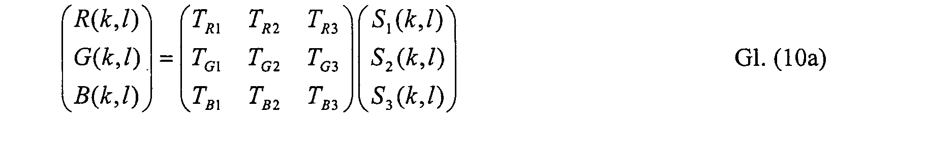
Löst man das Gleichungssystem auf, so erhält man die Intensitäten S1(k,l), S2(k,l) und
S3(k,l) der einzelnen Signale für jeden Bildpunkt k,l

Die Ergebnisse der Gl( 12) lassen sich zusammenfassen
Das Farbbild läßt sich somit in die Abbildungen der drei emittierenden Signale trennen. Den einzelnen Signalen können dann Grauwerte oder Falschfarben zugeordnet werden. Es sei nochmals darauf hingewiesen, daß für eine gute Trennung der Signale die einzelnen Signale frequenzmäßig nicht zu nahe beieinander liegen sollen und einzelne Transmissionskoeffizienten nicht beliebig klein werden sollen. Die Gleichungen lassen sich für zwei unterschiedliche Marker entsprechend vereinfachen.The color image can thus be separated into the images of the three emitting signals. Gray values or false colors can then be assigned to the individual signals. It it should be pointed out again that for a good separation of the signals the individual Signals should not be too close in frequency and individual transmission coefficients should not become arbitrarily small. The equations can be used for two Simplify different markers accordingly.
Zur Kompensation des Fading-Effekts sind die zu unterschiedlichen Zeiten gemessenen Teilbilder jeweils nach Gl. (13) in die Signale S1t, S2t, S3t aufzutrennen. Die Berechnung der Kompensation der einzelnen Signale erfolgt dann entsprechend den oben angegebenen Verfahren für jedes fluoreszierende Signal getrennt. Entsprechend werden die Verfahren zur Bestimmung der Verstärkungsfaktoren auf die einzelnen Signale bzw. deren Bilder angewandt.To compensate for the fading effect, the partial images measured at different times are each according to Eq. (13) into the signals S 1t , S 2t , S 3t . The compensation of the individual signals is then calculated separately for each fluorescent signal in accordance with the above-mentioned methods. The methods for determining the amplification factors are accordingly applied to the individual signals or their images.
Die Realisierung der angegebenen Beziehungen ist mit speziellen Rechenwerken der Signalverarbeitung möglich. Speziell für die Trennung der einzelnen Emissionssignale läßt sich, wie in Figur 9 dargestellt, ein einfaches Rechenwerk angeben, bei dem im Pipelineverfahren alle Rechenoperationen parallel ablaufen können. Ein solcher Pipelinerechner enthält 9 Multiplikationsstufen und 6 Additionsstufen. Entsprechende Schaltungen sind für die übrigen Rechenschritte angebbar. Die Realisierung aller Funktionen ist aber ebenfalls mit handelsüblichen Signalprozessoren oder auf einem Arbeitsrechner (PC) über eine entsprechende Software möglich.The realization of the specified relationships is possible with special calculators Signal processing possible. Especially for the separation of the individual emission signals a simple arithmetic unit, as shown in FIG Pipeline procedure all arithmetic operations can run in parallel. Such a Pipeline calculator contains 9 multiplication levels and 6 addition levels. Appropriate Circuits can be specified for the remaining calculation steps. The realization of all Functions is also with standard signal processors or on one Work computer (PC) possible using appropriate software.
Neben der Lösung des angegebenen linearen Gleichungssystems kann bei stark verrauschten Signalen die Trennung der einzelnen Fluoreszenz-Kanäle auch nach dem Prinzip eines "Fuzzy-Verfahrens" oder "NeuroFuzzy-Verfahrens" erfolgen. In diesem Fall werden dann für die Trennung der Beiträge der einzelnen Marker zu den Gesamtintensitäten der einzelnen Farbkanäle keine linearen Gleichungen zugrunde gelegt sondern Ungleichungen oder Relationen, anhand derer Näherungswerte für die Intensitäten der einzelnen Marker abgeschätzt werden.In addition to solving the specified system of linear equations, at strong noisy signals the separation of the individual fluorescence channels even after the Principle of a "fuzzy process" or "NeuroFuzzy process" take place. In this case are then used to separate the contributions of the individual markers Total intensities of the individual color channels are not based on linear equations but inequalities or relations, based on which approximate values for the intensities of the individual markers can be estimated.
Claims (19)
Applications Claiming Priority (2)
| Application Number | Priority Date | Filing Date | Title |
|---|---|---|---|
| DE2001109130 DE10109130B4 (en) | 2001-02-24 | 2001-02-24 | Method for recording and displaying fluorescence images with high spatial resolution |
| DE10109130 | 2001-02-24 |
Publications (2)
| Publication Number | Publication Date |
|---|---|
| EP1235424A2 true EP1235424A2 (en) | 2002-08-28 |
| EP1235424A3 EP1235424A3 (en) | 2009-09-02 |
Family
ID=7675482
Family Applications (1)
| Application Number | Title | Priority Date | Filing Date |
|---|---|---|---|
| EP01128671A Withdrawn EP1235424A3 (en) | 2001-02-24 | 2001-12-01 | Method for recording and displaying fluorescence images with high resolution |
Country Status (3)
| Country | Link |
|---|---|
| US (1) | US7113205B2 (en) |
| EP (1) | EP1235424A3 (en) |
| DE (1) | DE10109130B4 (en) |
Cited By (5)
| Publication number | Priority date | Publication date | Assignee | Title |
|---|---|---|---|---|
| WO2004038483A1 (en) * | 2002-10-28 | 2004-05-06 | Carl Zeiss Jena Gmbh | Method for improving depth discrimination in optical reproduction systems |
| WO2011036650A3 (en) * | 2009-09-28 | 2011-08-11 | Koninklijke Philips Electronics N.V. | Sensor device with imaging optics |
| DE102012107191A1 (en) | 2012-08-06 | 2014-02-06 | Jenoptik Optical Systems Gmbh | Method for high-resolution digital color imaging in microscopy, involves making additional images using different settings or shutter speed settings of color sensor for generating high-dynamic-range imaging at each scanning position |
| CN108492254A (en) * | 2018-03-27 | 2018-09-04 | 西安优艾智合机器人科技有限公司 | Image capturing system and method |
| CN113039428A (en) * | 2019-04-02 | 2021-06-25 | 贝克顿·迪金森公司 | Compensation editor |
Families Citing this family (12)
| Publication number | Priority date | Publication date | Assignee | Title |
|---|---|---|---|---|
| DE102005048006A1 (en) | 2005-10-06 | 2007-04-12 | Carl Zeiss Surgical Gmbh | Microscopy system and recording method for visualizing a fluorescence |
| DK2156370T3 (en) | 2007-05-14 | 2012-01-23 | Historx Inc | Compartment separation by pixel characterization using image data clustering |
| EP2162728B1 (en) * | 2007-06-15 | 2016-07-27 | Novartis AG | Microscope system and method for obtaining standardized sample data |
| CA2604317C (en) | 2007-08-06 | 2017-02-28 | Historx, Inc. | Methods and system for validating sample images for quantitative immunoassays |
| CA2596204C (en) | 2007-08-07 | 2019-02-26 | Historx, Inc. | Method and system for determining an optimal dilution of a reagent |
| WO2009029810A1 (en) | 2007-08-31 | 2009-03-05 | Historx, Inc. | Automatic exposure time selection for imaging tissue |
| EP2335221B8 (en) | 2008-09-16 | 2016-05-25 | Novartis AG | Reproducible quantification of biomarker expression |
| JP2010191377A (en) * | 2009-02-20 | 2010-09-02 | Olympus Corp | Microscope imaging system and operating method thereof |
| JP5466876B2 (en) * | 2009-05-14 | 2014-04-09 | オリンパス株式会社 | Image acquisition apparatus, image acquisition apparatus control method, and microscope system |
| DE102010063959A1 (en) * | 2010-12-22 | 2012-06-28 | Carl Zeiss Microlmaging Gmbh | Microscope with a color image sensor and microscopy method with a color image sensor |
| DE102014214750B3 (en) * | 2014-07-28 | 2015-06-11 | Reimar Lenz | Image acquisition system with fast-vibrating global shutter CMOS sensor |
| DE102022115989A1 (en) | 2022-06-27 | 2023-12-28 | Carl Zeiss Microscopy Gmbh | Microscopy system and method for color correction of microscope images |
Citations (1)
| Publication number | Priority date | Publication date | Assignee | Title |
|---|---|---|---|---|
| DE3837063C1 (en) * | 1988-10-31 | 1990-03-29 | Reimar Dr. 8000 Muenchen De Lenz |
Family Cites Families (15)
| Publication number | Priority date | Publication date | Assignee | Title |
|---|---|---|---|---|
| US4673988A (en) * | 1985-04-22 | 1987-06-16 | E.I. Du Pont De Nemours And Company | Electronic mosaic imaging process |
| JP3137632B2 (en) * | 1989-08-31 | 2001-02-26 | 富士通株式会社 | Optical communication system with optical fiber amplifier |
| JPH04326316A (en) * | 1991-04-26 | 1992-11-16 | Olympus Optical Co Ltd | Photographing device for microscope |
| DE4230724C1 (en) * | 1992-09-14 | 1993-10-14 | Leica Mikroskopie & Syst | Exposure control method and apparatus for fluorescence microphotography |
| DE19532897A1 (en) | 1994-09-27 | 1996-03-28 | Zeiss Carl Fa | Camera exposure control by image photometry in photographic microscope |
| US5866331A (en) * | 1995-10-20 | 1999-02-02 | University Of Massachusetts | Single molecule detection by in situ hybridization |
| US5798801A (en) * | 1996-05-08 | 1998-08-25 | U.S. Philips Corporation | Arrangement for providing vivid color in a television signal |
| WO1998017992A2 (en) * | 1996-10-25 | 1998-04-30 | Applied Imaging, Inc. | Multifluor-fluorescence in situ hybridization (m-fish) imaging techniques using multiple multiband filters with image registration |
| JP3583618B2 (en) * | 1998-06-15 | 2004-11-04 | 富士通株式会社 | IMAGE PROCESSING DEVICE, IMAGE PROCESSING METHOD, AND COMPUTER-READABLE RECORDING MEDIUM RECORDING PROGRAM FOR CAUSING COMPUTER TO EXECUTE THE METHOD |
| JP3892172B2 (en) * | 1998-07-24 | 2007-03-14 | 松下電器産業株式会社 | Solid-state imaging device |
| JP3375557B2 (en) * | 1999-01-29 | 2003-02-10 | 松下電器産業株式会社 | Video signal processing device |
| US6650779B2 (en) * | 1999-03-26 | 2003-11-18 | Georgia Tech Research Corp. | Method and apparatus for analyzing an image to detect and identify patterns |
| IL133243A0 (en) * | 1999-03-30 | 2001-03-19 | Univ Ramot | A method and system for super resolution |
| DE10017551C2 (en) | 2000-04-08 | 2002-10-24 | Carl Zeiss Vision Gmbh | Process for cyclic, interactive image analysis and computer system and computer program for executing the process |
| WO2002009424A2 (en) * | 2000-07-21 | 2002-01-31 | The Trustees Of Columbia University In The City Of New York | Method and apparatus for image mosaicing |
-
2001
- 2001-02-24 DE DE2001109130 patent/DE10109130B4/en not_active Expired - Fee Related
- 2001-12-01 EP EP01128671A patent/EP1235424A3/en not_active Withdrawn
-
2002
- 2002-02-21 US US10/078,688 patent/US7113205B2/en not_active Expired - Lifetime
Patent Citations (1)
| Publication number | Priority date | Publication date | Assignee | Title |
|---|---|---|---|---|
| DE3837063C1 (en) * | 1988-10-31 | 1990-03-29 | Reimar Dr. 8000 Muenchen De Lenz |
Non-Patent Citations (2)
| Title |
|---|
| BÖCKER W ET AL: "Automated cell cycle analysis with fluorescence microscopy and image analysis", PHYSICS IN MEDICINE AND BIOLOGY, INSTITUTE OF PHYSICS PUBLISHING, BRISTOL GB, vol. 41, 1 January 1996 (1996-01-01), pages 523 - 527, XP002257574, ISSN: 0031-9155, DOI: 10.1088/0031-9155/41/3/013 * |
| ROST F W D ED - ROST ET AL: "Quantitative fluorescence microscopy passage", 1 March 1991, QUANTITATIVE FLUORESCENCE MICROSCOPY, CAMBRIDGE UNIVERSITY PRESS, GB, PAGE(S) 10, ISBN: 978-0-521-39422-2, XP002537533 * |
Cited By (8)
| Publication number | Priority date | Publication date | Assignee | Title |
|---|---|---|---|---|
| WO2004038483A1 (en) * | 2002-10-28 | 2004-05-06 | Carl Zeiss Jena Gmbh | Method for improving depth discrimination in optical reproduction systems |
| US7335866B2 (en) | 2002-10-28 | 2008-02-26 | Carl Zeiss Microimaging Gmbh | Method for improving depth discrimination in optical reproduction systems |
| WO2011036650A3 (en) * | 2009-09-28 | 2011-08-11 | Koninklijke Philips Electronics N.V. | Sensor device with imaging optics |
| CN102713571A (en) * | 2009-09-28 | 2012-10-03 | 皇家飞利浦电子股份有限公司 | Sensor device with imaging optics |
| US9250181B2 (en) | 2009-09-28 | 2016-02-02 | Koninklijke Philips N.V. | Sensor device with imaging optics |
| DE102012107191A1 (en) | 2012-08-06 | 2014-02-06 | Jenoptik Optical Systems Gmbh | Method for high-resolution digital color imaging in microscopy, involves making additional images using different settings or shutter speed settings of color sensor for generating high-dynamic-range imaging at each scanning position |
| CN108492254A (en) * | 2018-03-27 | 2018-09-04 | 西安优艾智合机器人科技有限公司 | Image capturing system and method |
| CN113039428A (en) * | 2019-04-02 | 2021-06-25 | 贝克顿·迪金森公司 | Compensation editor |
Also Published As
| Publication number | Publication date |
|---|---|
| DE10109130B4 (en) | 2015-02-19 |
| US20020176007A1 (en) | 2002-11-28 |
| US7113205B2 (en) | 2006-09-26 |
| EP1235424A3 (en) | 2009-09-02 |
| DE10109130A1 (en) | 2002-09-05 |
Similar Documents
| Publication | Publication Date | Title |
|---|---|---|
| DE3910035C2 (en) | ||
| DE10109130B4 (en) | Method for recording and displaying fluorescence images with high spatial resolution | |
| DE102006011707B4 (en) | Method and device for producing a structure-free fiberscopic recording | |
| DE2952422C3 (en) | Method and device for processing an X-ray image in an X-ray image copying system | |
| DE60133160T2 (en) | Digital image processing method and apparatus for brightness adjustment of digital images | |
| DE60314692T2 (en) | Digital image method and apparatus for assembling removal of the mosaic effect and correction of bad pixels | |
| DE19616440A1 (en) | Method and device for obtaining a full color image or multispectral image from image data of a CCD image sensor with a mosaic color filter | |
| DE112012004493B4 (en) | Color lighting control method to improve image quality in an imaging system | |
| EP1625936A2 (en) | Method for qualitative evaluation of a material with at least one identification characteristic | |
| DE10217860A1 (en) | Dust compensation method for an image scanner with a moving document | |
| DE112016001559T5 (en) | Imaging system that uses structured light for deep recovery | |
| DE69927239T2 (en) | SYSTEM AND METHOD FOR PROCESSING PICTURES | |
| DE112014006672T5 (en) | An image processing apparatus, an image forming apparatus, a microscope system, an image processing method and an image processing program | |
| EP2147346B1 (en) | Device and method for compensating color displacements in fiber optic imaging systems | |
| DE60004595T2 (en) | Filtering defective picture elements in digital imaging devices | |
| DE112017004403T5 (en) | ENDOSCOPY SYSTEM AND CHARACTERISTIC AMOUNTING CALCULATION METHOD | |
| DE102007014413A1 (en) | Method and device for evaluating fluorescence images | |
| DE102019107267A1 (en) | Process for high-resolution scanning microscopy | |
| DE102008015979A1 (en) | Moving picture processing system and moving picture processing method | |
| DE60102411T2 (en) | Device for determining the best image from a two-resolution photosensor | |
| DE112019004373T5 (en) | SPECTROSCOPIC IMAGING DEVICE AND FLUORESCENCE MONITORING DEVICE | |
| EP1158771A2 (en) | Defect detection and correction in reference strips for the calibration of scanning devices | |
| EP2955691B1 (en) | Device for determining of colour fraction of an image pixel of a BAYER matrix | |
| EP1397002B1 (en) | A gradient based method for the interpolation of picture elements | |
| DE102017112484A1 (en) | Method and device for image correction |
Legal Events
| Date | Code | Title | Description |
|---|---|---|---|
| PUAI | Public reference made under article 153(3) epc to a published international application that has entered the european phase |
Free format text: ORIGINAL CODE: 0009012 |
|
| AK | Designated contracting states |
Kind code of ref document: A2 Designated state(s): AT BE CH CY DE DK ES FI FR GB GR IE IT LI LU MC NL PT SE TR |
|
| AX | Request for extension of the european patent |
Free format text: AL;LT;LV;MK;RO;SI |
|
| RAP1 | Party data changed (applicant data changed or rights of an application transferred) |
Owner name: CARL ZEISS Owner name: CARL-ZEISS-STIFTUNG TRADING AS CARL ZEISS |
|
| PUAL | Search report despatched |
Free format text: ORIGINAL CODE: 0009013 |
|
| AK | Designated contracting states |
Kind code of ref document: A3 Designated state(s): AT BE CH CY DE DK ES FI FR GB GR IE IT LI LU MC NL PT SE TR |
|
| AX | Request for extension of the european patent |
Extension state: AL LT LV MK RO SI |
|
| 17P | Request for examination filed |
Effective date: 20091125 |
|
| 17Q | First examination report despatched |
Effective date: 20100112 |
|
| AKX | Designation fees paid |
Designated state(s): DE FR GB |
|
| RAP1 | Party data changed (applicant data changed or rights of an application transferred) |
Owner name: CARL-ZEISS-STIFTUNG TRADING AS CARL ZEISS Owner name: CARL ZEISS AG |
|
| RAP1 | Party data changed (applicant data changed or rights of an application transferred) |
Owner name: CARL ZEISS AG |
|
| RAP1 | Party data changed (applicant data changed or rights of an application transferred) |
Owner name: CARL ZEISS MICROSCOPY GMBH |
|
| STAA | Information on the status of an ep patent application or granted ep patent |
Free format text: STATUS: THE APPLICATION HAS BEEN WITHDRAWN |
|
| 18W | Application withdrawn |
Effective date: 20180423 |
|
| RIC1 | Information provided on ipc code assigned before grant |
Ipc: H04N 3/15 20060101AFI20020619BHEP Ipc: G02B 21/36 20060101ALI20020619BHEP |