EP1234980A2 - Unité de pompage pour nettoyeur haute pression - Google Patents
Unité de pompage pour nettoyeur haute pression Download PDFInfo
- Publication number
- EP1234980A2 EP1234980A2 EP02003405A EP02003405A EP1234980A2 EP 1234980 A2 EP1234980 A2 EP 1234980A2 EP 02003405 A EP02003405 A EP 02003405A EP 02003405 A EP02003405 A EP 02003405A EP 1234980 A2 EP1234980 A2 EP 1234980A2
- Authority
- EP
- European Patent Office
- Prior art keywords
- pressure
- holding element
- valve body
- line
- pump unit
- Prior art date
- Legal status (The legal status is an assumption and is not a legal conclusion. Google has not performed a legal analysis and makes no representation as to the accuracy of the status listed.)
- Withdrawn
Links
Images

Classifications
-
- F—MECHANICAL ENGINEERING; LIGHTING; HEATING; WEAPONS; BLASTING
- F16—ENGINEERING ELEMENTS AND UNITS; GENERAL MEASURES FOR PRODUCING AND MAINTAINING EFFECTIVE FUNCTIONING OF MACHINES OR INSTALLATIONS; THERMAL INSULATION IN GENERAL
- F16K—VALVES; TAPS; COCKS; ACTUATING-FLOATS; DEVICES FOR VENTING OR AERATING
- F16K15/00—Check valves
- F16K15/02—Check valves with guided rigid valve members
- F16K15/04—Check valves with guided rigid valve members shaped as balls
- F16K15/044—Check valves with guided rigid valve members shaped as balls spring-loaded
-
- B—PERFORMING OPERATIONS; TRANSPORTING
- B08—CLEANING
- B08B—CLEANING IN GENERAL; PREVENTION OF FOULING IN GENERAL
- B08B2203/00—Details of cleaning machines or methods involving the use or presence of liquid or steam
- B08B2203/02—Details of machines or methods for cleaning by the force of jets or sprays
- B08B2203/027—Pump details
Definitions
- the invention relates to a pump unit for a high-pressure cleaning device with at least one with a suction line and with a pressure line connected pump chamber, one from the pressure line to Suction line returning bypass line and with a closing valve in the bypass line, which under the action a valve body a spring against the direction of flow in the bypass line presses into a closed position against a sealing seat.
- Such a pump unit for a high-pressure cleaning device is, for example known from DE 297 12 659 U1.
- the elastically deformable holding element thus holds the valve body in the open position and thus acts the force of the valve body in the Closing position shifting spring against this additional Retention force is only effective when the valve body in the open position is postponed. So this is the closing force increased after opening the closing valve, you get a hysteresis for the valve body, the force necessary for opening is higher than the force required to keep the closing valve open once necessary is. This leaves the valve body open safely in the open position until the pressure in the pressure line is below a value that is significantly below the pressure value which the closing valve is opened. Pressure fluctuations in the pressure line and the pressure drop through the opening of the bypass line occurs, do not lead to the closing valve being closed again in the bypass line so that flutter is prevented.
- the holding element can, for example, the valve body by an in immersing the trajectory of the valve body, elastic from the Apply a restraining force to the area that can be moved. So that the valve body is, so to speak, held in positive engagement, The valve body is only released if it is in the movement path immersed areas of the holding element from the Valve body to be displaced laterally, and this is a certain additional strength needed.
- the Holding element the valve body by a frictional connection to the valve body applied area with a retaining force.
- the holding element is annular and the valve body in the open position encloses on the side.
- the valve body in the open position encloses on the side.
- the holding element in cross section is square.
- the holding element is preferably made of a polymer on the Base of polyurethane or polyester and it is convenient if the Softness of the material used similar to that of soft seals is.
- valve body designed as a ball.
- the closing force of the spring of the closing valve is selected such that it is closed when the outlet of the pressure line is open and the pressure P 0 is correspondingly low in the pressure line and is opened when the outlet of the pressure line is open and the pressure P 1 is correspondingly increased in the pressure line becomes.
- the bypass line becomes when the pressure line is fully open kept closed when throttling the line cross-section in the pressure line - and, of course, also when completely closed the pressure line - the bypass line is opened against it, so that a Partial flow or the total amount of liquid delivered via the bypass line is returned to the suction line.
- the flow path, which is opened by the open bypass valve has a limited cross section, which leads to a division of the flow paths between the outlet of the pressure line and the bypass line and thus to the maintenance of a pressure in the pressure line when the outlet cross section of the pressure line is partially open , which is above the pressure P 0 when the outlet of the pressure line is fully open, but which may also be below this pressure P 0 if the additional restraining forces exerted by the holding element on the valve body are large enough.
- the protection of the invention also relates to a closing valve for Insert into a bypass line as described above.
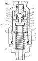
- the pump unit 1 shown in the drawing is in a Drawing not shown high pressure cleaning device used in the liquid supplied via a supply line, preferably Water, which is fed to a pressure line via a high pressure pump, which delivers the liquid under high pressure through an outlet, whereby the outlet in the usual way as a spray gun or spray lance a closing valve is formed.
- a supply line preferably Water
- a high pressure pump which delivers the liquid under high pressure through an outlet, whereby the outlet in the usual way as a spray gun or spray lance a closing valve is formed.
- An injector insert 8 is inserted into the pressure line 5 and has a constriction 9 of the cross section of the pressure line 5 generated, and in the area the constriction 9 branches off a connecting line 10, which with one formed by the injector insert 8 and sealed on both sides Annulus 11 communicates.
- a connecting line 10 which with one formed by the injector insert 8 and sealed on both sides Annulus 11 communicates.
- this one opens laterally a chemical suction line 12 adjoining the pressure line 5, in which a spring-loaded check valve 13 is arranged, which can be opened by the vacuum created by the injector insert 8 generates flowing liquid in the area of the constriction 9, so that through the chemical suction line 12th Chemical sucked and the flowing through the pressure line 5 Liquid can be added.
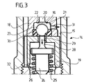
- valve seat body 18 has a central flow channel 20 which is stepped into a the guide body 19 opens the closed valve chamber 21 step transition between the flow channel 20 and the valve chamber 21 forms a sealing seat 22 for a spherical valve body 23 which is received in the valve chamber 21 and which in the valve chamber 21 can be moved so that it is optionally in is in a closed position on the sealing seat 22 and in an open position is removed from the sealing seat 22.
- a closing body 24 is longitudinally displaceable in the guide body 19 guided, on which a helical closing spring 25 is supported, the other end in a central bore 26 in the bottom of the valve chamber 15 immersed and supported there on an annular shoulder 27, which is formed by a step-like narrowing of the bore 26.
- the closing body 24 is thereby in the interior of the guide body 19 moved towards the valve seat body 18 and protrudes with a pin-shaped projection 28 through a central opening 29 in the guide body 19 through, this projection 28 occurs in this way the valve chamber 21 and lies on the spherical valve body 23 on by the closing body 24 under the force of the closing spring 25 is pressed against the sealing seat 22.
- annular holding element 30 On the side opposite the sealing seat 22 is in the valve chamber 21 inserted an annular holding element 30, which one has rectangular cross section and made of a soft plastic material consists, for example, of a polymer based on polyurethane or polyester base.
- the diameter of this annular holding element 30 is chosen so that this is on the outside on the Inner wall of the valve chamber 21 supports the inner diameter of the Holding element 30 is smaller than the outer diameter of the spherical Valve body 23. If this valve body 23 against the Moved force of the closing spring 25 into the open position, the spherical dips Thereby valve body 23 into the opening of the annular holding element 30 and deforms this holding element 30, i.e. the spherical Valve body 23 urges the material of holding element 30 radially outwards, as is clear from FIG. 3.
- valve chamber 21 is connected to the valve chamber via a radial bore 31 15 in connection, and this in turn via a radial bore 32 with the central bore 26 in the bottom of the valve space 15. In this way, there is a continuous flow path over the Flow channel 20, the valve chamber 21, the bore 31, the valve chamber 15, the bore 32 and the bore 26, this flow path forms the bypass line.
- This flow path has when open Valve body 23 has a limited cross section, so that this flow path described produces a throttling effect and thereby allows only a limited amount of liquid to pass through.
Landscapes
- Engineering & Computer Science (AREA)
- General Engineering & Computer Science (AREA)
- Mechanical Engineering (AREA)
- Details Of Reciprocating Pumps (AREA)
- Reciprocating Pumps (AREA)
Applications Claiming Priority (2)
| Application Number | Priority Date | Filing Date | Title |
|---|---|---|---|
| DE20103142U | 2001-02-22 | ||
| DE20103142U DE20103142U1 (de) | 2001-02-22 | 2001-02-22 | Pumpeneinheit für ein Hochdruckreinigungsgerät |
Publications (2)
| Publication Number | Publication Date |
|---|---|
| EP1234980A2 true EP1234980A2 (fr) | 2002-08-28 |
| EP1234980A3 EP1234980A3 (fr) | 2003-12-10 |
Family
ID=7953371
Family Applications (1)
| Application Number | Title | Priority Date | Filing Date |
|---|---|---|---|
| EP02003405A Withdrawn EP1234980A3 (fr) | 2001-02-22 | 2002-02-14 | Unité de pompage pour nettoyeur haute pression |
Country Status (2)
| Country | Link |
|---|---|
| EP (1) | EP1234980A3 (fr) |
| DE (1) | DE20103142U1 (fr) |
Cited By (5)
| Publication number | Priority date | Publication date | Assignee | Title |
|---|---|---|---|---|
| DE102007017970A1 (de) * | 2007-04-11 | 2008-10-16 | Alfred Kärcher Gmbh & Co. Kg | Hochdruckreinigungsgerät |
| US8439653B2 (en) | 2009-10-01 | 2013-05-14 | Alfred Kaercher Gmbh & Co. Kg | Pump for a high-pressure cleaning apparatus |
| US8568109B2 (en) | 2009-10-01 | 2013-10-29 | Alfred Kaercher Gmbh & Co. Kg | Pump for a high-pressure cleaning device |
| US8684699B2 (en) | 2009-10-01 | 2014-04-01 | Alfred Kaercher Gmbh & Co. Kg | Pump for a high-pressure cleaning appliance |
| CN113107839A (zh) * | 2020-01-13 | 2021-07-13 | 施瓦本冶金工程汽车有限公司 | 阀装置,特别是带有压入式球保持件的止回阀 |
Family Cites Families (5)
| Publication number | Priority date | Publication date | Assignee | Title |
|---|---|---|---|---|
| US3421547A (en) * | 1965-11-30 | 1969-01-14 | Alkon Products Corp | Check valve mechanism |
| DE4445520C1 (de) * | 1994-12-20 | 1996-07-04 | Kaercher Gmbh & Co Alfred | Kolbenpumpe für ein Hochdruckreinigungsgerät |
| DE19711456A1 (de) * | 1997-03-19 | 1998-09-24 | Schaeffler Waelzlager Ohg | Rückschlagventil |
| AT407188B (de) * | 1997-07-16 | 2001-01-25 | Hoerbiger Hydraulik | Ventil |
| DE29712659U1 (de) * | 1997-07-17 | 1997-09-18 | Alfred Kärcher GmbH & Co, 71364 Winnenden | Hochdruckreinigungsgerät |
-
2001
- 2001-02-22 DE DE20103142U patent/DE20103142U1/de not_active Expired - Lifetime
-
2002
- 2002-02-14 EP EP02003405A patent/EP1234980A3/fr not_active Withdrawn
Cited By (7)
| Publication number | Priority date | Publication date | Assignee | Title |
|---|---|---|---|---|
| DE102007017970A1 (de) * | 2007-04-11 | 2008-10-16 | Alfred Kärcher Gmbh & Co. Kg | Hochdruckreinigungsgerät |
| CN101641165B (zh) * | 2007-04-11 | 2012-11-07 | 阿尔弗雷德·凯驰两合公司 | 高压清洗设备 |
| US8790092B2 (en) | 2007-04-11 | 2014-07-29 | Alfred Kaercher Gmbh & Co. Kg | High-pressure cleaning appliance |
| US8439653B2 (en) | 2009-10-01 | 2013-05-14 | Alfred Kaercher Gmbh & Co. Kg | Pump for a high-pressure cleaning apparatus |
| US8568109B2 (en) | 2009-10-01 | 2013-10-29 | Alfred Kaercher Gmbh & Co. Kg | Pump for a high-pressure cleaning device |
| US8684699B2 (en) | 2009-10-01 | 2014-04-01 | Alfred Kaercher Gmbh & Co. Kg | Pump for a high-pressure cleaning appliance |
| CN113107839A (zh) * | 2020-01-13 | 2021-07-13 | 施瓦本冶金工程汽车有限公司 | 阀装置,特别是带有压入式球保持件的止回阀 |
Also Published As
| Publication number | Publication date |
|---|---|
| EP1234980A3 (fr) | 2003-12-10 |
| DE20103142U1 (de) | 2001-05-10 |
Similar Documents
| Publication | Publication Date | Title |
|---|---|---|
| DE2103948A1 (de) | Automatisches Ventil | |
| DE10259808B4 (de) | Strahlpumpe | |
| DE2362422A1 (de) | Selbsttaetig absperrende zapfpistole | |
| CH632326A5 (de) | Stroemungsregelventil. | |
| DE3248622A1 (de) | Hochdruckreinigungsgeraet | |
| EP2131970B1 (fr) | Appareil de nettoyage à haute pression | |
| DE3810341C2 (fr) | ||
| DE3323324C2 (de) | Verfahren und Vorrichtung zum Steuern eines Rohrtrenners in Abhängigkeit einer an einer Vergleichsstelle vorgegebenen Druckdifferenz | |
| EP2428485B1 (fr) | Buse de distribution | |
| EP1234980A2 (fr) | Unité de pompage pour nettoyeur haute pression | |
| EP2453804B1 (fr) | Instrument commandé par gaz comprimé, en particulier instrument chirurgical | |
| DE4311856A1 (de) | Druckbegrenzungsventil | |
| DE19650379A1 (de) | Ventilanordnung mit direkt betätigtem Ventilkörper | |
| DE4219663A1 (de) | Flüssigkeits-Dosierpumpe | |
| EP2275037B1 (fr) | Instrument entraîné par gaz comprimé | |
| DE60301572T2 (de) | Abgabepumpe für medien | |
| EP4133351B1 (fr) | Vanne de réduction de pression | |
| DE29624335U1 (de) | Ventilanordnung mit direkt betätigtem Ventilkörper | |
| EP4163249B1 (fr) | Pistolet disbributeur doté d'un dispositif d'antiretournement | |
| DE102010044824B4 (de) | Ventil | |
| DE102006034276B3 (de) | Warmwasserbereiter | |
| DE19851791A1 (de) | Ventilanordnung und Vorrichtung mit einer solchen Ventilanordung | |
| DE4330651A1 (de) | Zusatzeinrichtung für eine Wasserentnahmestelle | |
| DE4141172B4 (de) | Vorrichtung zum Umstellen eines Ventilgliedes an einer Sanitärarmatur | |
| DE4221577C2 (de) | Vorrichtung zur Reinigung von Rohrleitungen |
Legal Events
| Date | Code | Title | Description |
|---|---|---|---|
| PUAI | Public reference made under article 153(3) epc to a published international application that has entered the european phase |
Free format text: ORIGINAL CODE: 0009012 |
|
| AK | Designated contracting states |
Kind code of ref document: A2 Designated state(s): AT BE CH CY DE DK ES FI FR GB GR IE IT LI LU MC NL PT SE TR |
|
| AX | Request for extension of the european patent |
Free format text: AL;LT;LV;MK;RO;SI |
|
| RAP1 | Party data changed (applicant data changed or rights of an application transferred) |
Owner name: ALFRED KAERCHER GMBH & CO. KG |
|
| PUAL | Search report despatched |
Free format text: ORIGINAL CODE: 0009013 |
|
| AK | Designated contracting states |
Kind code of ref document: A3 Designated state(s): AT BE CH CY DE DK ES FI FR GB GR IE IT LI LU MC NL PT SE TR |
|
| AX | Request for extension of the european patent |
Extension state: AL LT LV MK RO SI |
|
| RIC1 | Information provided on ipc code assigned before grant |
Ipc: 7F 16K 15/04 B Ipc: 7B 08B 3/02 B Ipc: 7F 04B 49/035 A |
|
| 17P | Request for examination filed |
Effective date: 20040225 |
|
| AKX | Designation fees paid |
Designated state(s): AT BE CH CY DE DK ES FI FR GB GR IE IT LI LU MC NL PT SE TR |
|
| GRAP | Despatch of communication of intention to grant a patent |
Free format text: ORIGINAL CODE: EPIDOSNIGR1 |
|
| 17Q | First examination report despatched |
Effective date: 20040325 |
|
| STAA | Information on the status of an ep patent application or granted ep patent |
Free format text: STATUS: THE APPLICATION IS DEEMED TO BE WITHDRAWN |
|
| 18D | Application deemed to be withdrawn |
Effective date: 20050127 |