EP1234957A2 - Commande de soupape pour moteur à combustion interne - Google Patents
Commande de soupape pour moteur à combustion interne Download PDFInfo
- Publication number
- EP1234957A2 EP1234957A2 EP02002529A EP02002529A EP1234957A2 EP 1234957 A2 EP1234957 A2 EP 1234957A2 EP 02002529 A EP02002529 A EP 02002529A EP 02002529 A EP02002529 A EP 02002529A EP 1234957 A2 EP1234957 A2 EP 1234957A2
- Authority
- EP
- European Patent Office
- Prior art keywords
- valve
- holding part
- cam
- compensation device
- play compensation
- Prior art date
- Legal status (The legal status is an assumption and is not a legal conclusion. Google has not performed a legal analysis and makes no representation as to the accuracy of the status listed.)
- Granted
Links
- 238000002485 combustion reaction Methods 0.000 title claims abstract description 5
- 241001433879 Camarea Species 0.000 claims description 9
- 230000005540 biological transmission Effects 0.000 claims description 9
- 230000006835 compression Effects 0.000 claims description 8
- 238000007906 compression Methods 0.000 claims description 8
- 230000000903 blocking effect Effects 0.000 claims description 6
- 238000006073 displacement reaction Methods 0.000 claims description 4
- 238000000034 method Methods 0.000 abstract 1
- 238000009795 derivation Methods 0.000 description 2
- 230000007704 transition Effects 0.000 description 2
- 238000011038 discontinuous diafiltration by volume reduction Methods 0.000 description 1
- 230000000694 effects Effects 0.000 description 1
Images

Classifications
-
- F—MECHANICAL ENGINEERING; LIGHTING; HEATING; WEAPONS; BLASTING
- F01—MACHINES OR ENGINES IN GENERAL; ENGINE PLANTS IN GENERAL; STEAM ENGINES
- F01L—CYCLICALLY OPERATING VALVES FOR MACHINES OR ENGINES
- F01L9/00—Valve-gear or valve arrangements actuated non-mechanically
- F01L9/10—Valve-gear or valve arrangements actuated non-mechanically by fluid means, e.g. hydraulic
- F01L9/11—Valve-gear or valve arrangements actuated non-mechanically by fluid means, e.g. hydraulic in which the action of a cam is being transmitted to a valve by a liquid column
-
- F—MECHANICAL ENGINEERING; LIGHTING; HEATING; WEAPONS; BLASTING
- F01—MACHINES OR ENGINES IN GENERAL; ENGINE PLANTS IN GENERAL; STEAM ENGINES
- F01L—CYCLICALLY OPERATING VALVES FOR MACHINES OR ENGINES
- F01L1/00—Valve-gear or valve arrangements, e.g. lift-valve gear
- F01L1/02—Valve drive
- F01L1/04—Valve drive by means of cams, camshafts, cam discs, eccentrics or the like
- F01L1/08—Shape of cams
-
- F—MECHANICAL ENGINEERING; LIGHTING; HEATING; WEAPONS; BLASTING
- F01—MACHINES OR ENGINES IN GENERAL; ENGINE PLANTS IN GENERAL; STEAM ENGINES
- F01L—CYCLICALLY OPERATING VALVES FOR MACHINES OR ENGINES
- F01L1/00—Valve-gear or valve arrangements, e.g. lift-valve gear
- F01L1/34—Valve-gear or valve arrangements, e.g. lift-valve gear characterised by the provision of means for changing the timing of the valves without changing the duration of opening and without affecting the magnitude of the valve lift
- F01L1/344—Valve-gear or valve arrangements, e.g. lift-valve gear characterised by the provision of means for changing the timing of the valves without changing the duration of opening and without affecting the magnitude of the valve lift changing the angular relationship between crankshaft and camshaft, e.g. using helicoidal gear
- F01L1/3442—Valve-gear or valve arrangements, e.g. lift-valve gear characterised by the provision of means for changing the timing of the valves without changing the duration of opening and without affecting the magnitude of the valve lift changing the angular relationship between crankshaft and camshaft, e.g. using helicoidal gear using hydraulic chambers with variable volume to transmit the rotating force
- F01L2001/34423—Details relating to the hydraulic feeding circuit
- F01L2001/34446—Fluid accumulators for the feeding circuit
Definitions
- the invention relates to a valve train for an internal combustion engine, with a driven Cam element and with one of the cam area of the rotating Cam element against a closing spring openable valve, which is a hydraulic Backlash compensation device with a supply line provided with a check valve and a derivative for a pressure transmission medium, the derivative by means of a spring-loaded locking element over the cam area of the Cam element is closed and open over the base circle area.
- Mechanical valve trains with hydraulic lash adjusters are in large number and known in different versions. They serve the valve to adjust in the valve seat so that it over the base circle area of the cam element is actually closed properly.
- the adjustment results from the level of the pressure transmission medium, in particular oil, in the pressure chamber caused by Change in the inflow can be set.
- the derivative shows an increased Flow resistance, for example due to a small cross section, a throttle element or the like, in order to avoid rapid drainage. Because such Valve clearance compensation has the disadvantage that the medium from the pressure chamber too during the opening of the valve, i.e. during the application by the The cam area of the cam element exits via the derivative was described in DE 41 24 184 A proposed a valve train of the type mentioned, the tappet includes.
- a sliding inner sleeve is arranged in the cup, and in the space between the cup and the inner sleeve engages in the cylinder head an adjustable intermediate sleeve, with passage openings in the sleeves are opened or closed depending on the position of the cam element. On this is the exit of the pressure transmission medium during the valve opening prevented, and the game compensation element can not be compressed. The Through openings are only cleared again at the transition to the base circle area, so that the valve clearance is established.
- the invention has now set itself the task of switching the locking element to simplify, and suggests that the base circle area of the cam member is provided with a space into which the locking element or one assigned to it Holding part can occur.
- the free space opens from the transition from the cam area to the base circle area of the cam element and the locking element can under the action of a spring be moved so that the derivation of the pressure transmission element is released becomes.
- the locking element can be in the pressure chamber of the hydraulic accumulator compensation device be arranged, it being displaceable in the valve axis lie and with a second end directly in the free space of the cam element can intervene.
- the blocking element is preferably laterally next to the Match compensation device arranged on the holding part, wherein the holding part Compression spring is assigned, which holds the holding part in the recess of the cam element suppressed.
- the holding part of the locking element is preferably displaceable on the play compensation device arranged, and the pressure spring between the game compensation device and the holding part provided.
- the holding part the game compensation device protrudes axially on both sides and limit stops for the displacement the game compensation device.
- the force of the compression spring is preferably essential less than that of the valve closing spring.
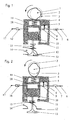
- a valve train for an intake or exhaust valve 13 of an internal combustion engine has one driven camshaft on which at least one cam element 1 is arranged, that opens the valve 13 against a valve spring 14.
- the cam element 1 has one Cam area and a base circle area in which one with respect to the Base circle 3 deepened space 2 is provided.
- a hydraulic lash adjuster provided between the cam element 1 and the valve 13 a piston 10 acting on the tappet of the valve 13, a cup-like Actuating cylinder 18, in which the piston 10 slidably engages, and a pressure chamber 14 between the piston 10 and the bottom of the actuating cylinder 18 comprises.
- the pressure room 14 is via a feed line 17 and a check valve 16 with a Pressure transmission medium, in particular oil, can be filled and via a discharge line 6 can be emptied, in which a check valve 9 and a throttle element 7 in a row are arranged.
- a holding part 19 is slidably arranged on the actuating cylinder 18, which projects axially on both sides via the actuating cylinder 18 and into the displacement path of the Actuating cylinder 18 has protruding limit stops 5, 11.
- the holding part 19 is further provided with a bottom on which the cam element 1 rests. Between the actuating cylinder 18 and the holding part 19, a compression spring 4 is provided, which Holding part 19 presses against the cam element 1.
- a locking element 8 is connected to the holding part 19, so that when the holding part 19 is moved, the locking element 8 is also moved, and the check valve 9 opens or closes.
- the valve train now works as follows: At the beginning of the opening phase of the valve 13, the cam element 1 has the position shown in FIG. 1, in which the on the contour of the base circle 3 between the free space 2 and the cam area lying circumferential section rests on the holding part 19. If the cam element 1 rotates in the direction of the arrow in the position shown in Fig. 2, the holding part 19 pushed down. The actuating cylinder 18 lies on the stop 5 of the holding part and is also moved. The check valve 16 blocks the feed line 17, and that Blocking element 8 blocks the discharge line 6, so that the one enclosed in the pressure chamber 14 Pressure transmission medium can not escape. The loading by the Cam element 1 is thus transmitted directly to the piston 10, which is on the valve lifter is applied.
- valve 13 lifts off the valve seat 12 and opens the inlet or Outlet region. With the further rotation in the position of FIG. 3, the relative remain Positions of all parts to each other unchanged, so that the valve 13 through the Valve spring 15 is moved back into the valve seat 12.
- the derivative 6 remains locked, and the volume of the pressure chamber 14 unchanged. Since also the actuating cylinder 18 abuts the stop 5, the holding part 19 follows the receding contour of the Cam area until base circle 3 is reached.
- the compression spring 4 takes over the further displacement of the Holding part 19, and the blocking element 8 from the check valve 9 - at least schematically - pulled out so that the derivative 6 is opened.
- excess Pressure transmission medium can be braked by the throttle element 7 from the Drain pressure chamber 14.
- a lower stop 15 of the holding element 19 limits the Effect of the compression spring 4, i.e. the actuating cylinder 18 can only touch the system on Stop 11 are moved, causing an excessive reduction in Pressure chamber volume is prevented despite the open shut-off valve 9.
Landscapes
- Engineering & Computer Science (AREA)
- Mechanical Engineering (AREA)
- General Engineering & Computer Science (AREA)
- Valve-Gear Or Valve Arrangements (AREA)
- Valve Device For Special Equipments (AREA)
- Electrical Control Of Air Or Fuel Supplied To Internal-Combustion Engine (AREA)
- Output Control And Ontrol Of Special Type Engine (AREA)
Priority Applications (1)
| Application Number | Priority Date | Filing Date | Title |
|---|---|---|---|
| AT02002529T ATE263309T1 (de) | 2001-02-21 | 2002-02-04 | Ventiltrieb für eine brennkraftmaschine |
Applications Claiming Priority (2)
| Application Number | Priority Date | Filing Date | Title |
|---|---|---|---|
| AT2682001 | 2001-02-21 | ||
| AT2682001 | 2001-02-21 |
Publications (3)
| Publication Number | Publication Date |
|---|---|
| EP1234957A2 true EP1234957A2 (fr) | 2002-08-28 |
| EP1234957A3 EP1234957A3 (fr) | 2003-01-08 |
| EP1234957B1 EP1234957B1 (fr) | 2004-03-31 |
Family
ID=3670472
Family Applications (1)
| Application Number | Title | Priority Date | Filing Date |
|---|---|---|---|
| EP02002529A Expired - Lifetime EP1234957B1 (fr) | 2001-02-21 | 2002-02-04 | Commande de soupape pour moteur à combustion interne |
Country Status (4)
| Country | Link |
|---|---|
| EP (1) | EP1234957B1 (fr) |
| AT (1) | ATE263309T1 (fr) |
| DE (1) | DE50200316D1 (fr) |
| ES (1) | ES2217209T3 (fr) |
Cited By (2)
| Publication number | Priority date | Publication date | Assignee | Title |
|---|---|---|---|---|
| WO2006037408A1 (fr) * | 2004-10-02 | 2006-04-13 | Schaeffler Kg | Mecanisme de distribution variable de moteur a combustion interne |
| WO2010012864A1 (fr) * | 2008-07-31 | 2010-02-04 | Wärtsilä Finland Oy | Dispositif de commande dans un moteur à piston |
Citations (1)
| Publication number | Priority date | Publication date | Assignee | Title |
|---|---|---|---|---|
| DE4124184A1 (de) | 1991-07-20 | 1993-01-21 | Schaeffler Waelzlager Kg | Hydraulischer tassenstoessel |
Family Cites Families (5)
| Publication number | Priority date | Publication date | Assignee | Title |
|---|---|---|---|---|
| DE1018880B (de) * | 1955-05-31 | 1957-11-07 | Albert Pomutz | Hydraulische Steuerung, insbesondere fuer die Ventile von Kolbenmaschinen |
| FR2464372A1 (fr) * | 1979-08-30 | 1981-03-06 | Semt | Procede et dispositif pour ameliorer le rendement d'un moteur a combustion interne par variation selective au taux de compression effectif selon le regime du moteur |
| DE4111610C2 (de) * | 1990-07-27 | 1998-07-30 | Audi Ag | Vorrichtung zur Veränderung der Steuerzeiten eines Gaswechselventils |
| JPH04301108A (ja) * | 1991-03-28 | 1992-10-23 | Aisin Seiki Co Ltd | バルブ停止装置付油圧リフタ |
| DE19653459A1 (de) * | 1996-12-20 | 1998-06-25 | Schaeffler Waelzlager Ohg | Stößel für einen Ventiltrieb einer Brennkraftmaschine |
-
2002
- 2002-02-04 AT AT02002529T patent/ATE263309T1/de not_active IP Right Cessation
- 2002-02-04 DE DE50200316T patent/DE50200316D1/de not_active Expired - Fee Related
- 2002-02-04 EP EP02002529A patent/EP1234957B1/fr not_active Expired - Lifetime
- 2002-02-04 ES ES02002529T patent/ES2217209T3/es not_active Expired - Lifetime
Patent Citations (1)
| Publication number | Priority date | Publication date | Assignee | Title |
|---|---|---|---|---|
| DE4124184A1 (de) | 1991-07-20 | 1993-01-21 | Schaeffler Waelzlager Kg | Hydraulischer tassenstoessel |
Cited By (2)
| Publication number | Priority date | Publication date | Assignee | Title |
|---|---|---|---|---|
| WO2006037408A1 (fr) * | 2004-10-02 | 2006-04-13 | Schaeffler Kg | Mecanisme de distribution variable de moteur a combustion interne |
| WO2010012864A1 (fr) * | 2008-07-31 | 2010-02-04 | Wärtsilä Finland Oy | Dispositif de commande dans un moteur à piston |
Also Published As
| Publication number | Publication date |
|---|---|
| ES2217209T3 (es) | 2004-11-01 |
| EP1234957A3 (fr) | 2003-01-08 |
| ATE263309T1 (de) | 2004-04-15 |
| EP1234957B1 (fr) | 2004-03-31 |
| DE50200316D1 (de) | 2004-05-06 |
Similar Documents
| Publication | Publication Date | Title |
|---|---|---|
| DE3876762T2 (de) | Vorrichtung zur ventilsteuerung in einer brennkraftmaschine. | |
| DE4429071C2 (de) | Vorrichtung zum Spannen und Verstellen eines als Kette ausgebildeten Umschlingungstriebes | |
| DE60018347T2 (de) | Verbesserungen in einer variablen Ventilsteuereinrichtung für eine Brennkraftmaschine | |
| EP3418513B1 (fr) | Dispositif de transmission de force | |
| EP0285877B1 (fr) | Dispositif de commande de soupape | |
| DE112014003482T5 (de) | Vorrichtung und Verfahren zur Einstellung des Spiels von Motorbremsen | |
| EP0324085B1 (fr) | Poussoir hydraulique | |
| AT519802B1 (de) | Ventilmechanismus für eine längenverstellbare Pleuelstange | |
| EP4004350B1 (fr) | Dispositif de commande de soupape variable assurant la fonction de freinage | |
| DE10029261A1 (de) | Nockenwellenverschwenkeinrichtung | |
| DE4116152A1 (de) | Einrichtung zur verstellung der drehwinkelzuordnung einer nockenwelle zu ihrem antriebselement | |
| DE4202506A1 (de) | Variabler ventiltrieb fuer ein hubventil | |
| EP1477638B1 (fr) | Commande de soupape variable | |
| DE4202542A1 (de) | Variabler ventiltrieb fuer ein hubventil | |
| DE102011008128B4 (de) | Hubkolben-Brennkraftmaschine mit variablem Verdichtungsverhältnis | |
| DE60310743T2 (de) | Vorrichtung zum ventilausschalten einer brennkraftmaschine | |
| EP1234957B1 (fr) | Commande de soupape pour moteur à combustion interne | |
| EP0193142A1 (fr) | Dispositif de frein moteur pour moteur à combustion interne | |
| DE1958627A1 (de) | Verstellvorrichtung fuer Ventilerhebungen | |
| DE4124184A1 (de) | Hydraulischer tassenstoessel | |
| DE4427271B4 (de) | Ventiltrieb für ein nockenbetätigtes, schließfederbestücktes Hubventil | |
| DE10124869C2 (de) | Hydraulische Steuereinrichtung für gleichwirkende Motorventile eines Dieselmotors | |
| DE102008049529B4 (de) | Brennkraftmaschine mit hydraulischem Ventilspielausgleich und innerer Abgasrückführung | |
| EP0323591A2 (fr) | Dispositif de réglage de l'injection à 2 points | |
| DE102020112545A1 (de) | Vorrichtung zur Betätigung von Auslassventilen einer Motorbremseinrichtung |
Legal Events
| Date | Code | Title | Description |
|---|---|---|---|
| PUAI | Public reference made under article 153(3) epc to a published international application that has entered the european phase |
Free format text: ORIGINAL CODE: 0009012 |
|
| AK | Designated contracting states |
Kind code of ref document: A2 Designated state(s): AT BE CH CY DE DK ES FI FR GB GR IE IT LI LU MC NL PT SE TR |
|
| AX | Request for extension of the european patent |
Free format text: AL;LT;LV;MK;RO;SI |
|
| PUAL | Search report despatched |
Free format text: ORIGINAL CODE: 0009013 |
|
| AK | Designated contracting states |
Kind code of ref document: A3 Designated state(s): AT BE CH CY DE DK ES FI FR GB GR IE IT LI LU MC NL PT SE TR |
|
| AX | Request for extension of the european patent |
Free format text: AL;LT;LV;MK;RO;SI |
|
| RIC1 | Information provided on ipc code assigned before grant |
Free format text: 7F 01L 9/02 A, 7F 01L 1/24 B |
|
| 17P | Request for examination filed |
Effective date: 20030616 |
|
| GRAP | Despatch of communication of intention to grant a patent |
Free format text: ORIGINAL CODE: EPIDOSNIGR1 |
|
| AKX | Designation fees paid |
Designated state(s): AT BE CH CY DE DK ES FI FR GB GR IE IT LI LU MC NL PT SE TR |
|
| GRAS | Grant fee paid |
Free format text: ORIGINAL CODE: EPIDOSNIGR3 |
|
| GRAA | (expected) grant |
Free format text: ORIGINAL CODE: 0009210 |
|
| RAP1 | Party data changed (applicant data changed or rights of an application transferred) |
Owner name: GE JENBACHER GMBH & CO. OHG |
|
| AK | Designated contracting states |
Kind code of ref document: B1 Designated state(s): AT BE CH CY DE DK ES FI FR GB GR IE IT LI LU MC NL PT SE TR |
|
| PG25 | Lapsed in a contracting state [announced via postgrant information from national office to epo] |
Ref country code: IE Free format text: LAPSE BECAUSE OF FAILURE TO SUBMIT A TRANSLATION OF THE DESCRIPTION OR TO PAY THE FEE WITHIN THE PRESCRIBED TIME-LIMIT Effective date: 20040331 Ref country code: TR Free format text: LAPSE BECAUSE OF FAILURE TO SUBMIT A TRANSLATION OF THE DESCRIPTION OR TO PAY THE FEE WITHIN THE PRESCRIBED TIME-LIMIT Effective date: 20040331 |
|
| REG | Reference to a national code |
Ref country code: CH Ref legal event code: EP Ref country code: GB Ref legal event code: FG4D Free format text: NOT ENGLISH |
|
| REG | Reference to a national code |
Ref country code: IE Ref legal event code: FG4D Free format text: GERMAN |
|
| REF | Corresponds to: |
Ref document number: 50200316 Country of ref document: DE Date of ref document: 20040506 Kind code of ref document: P |
|
| PG25 | Lapsed in a contracting state [announced via postgrant information from national office to epo] |
Ref country code: SE Free format text: LAPSE BECAUSE OF FAILURE TO SUBMIT A TRANSLATION OF THE DESCRIPTION OR TO PAY THE FEE WITHIN THE PRESCRIBED TIME-LIMIT Effective date: 20040630 Ref country code: DK Free format text: LAPSE BECAUSE OF FAILURE TO SUBMIT A TRANSLATION OF THE DESCRIPTION OR TO PAY THE FEE WITHIN THE PRESCRIBED TIME-LIMIT Effective date: 20040630 Ref country code: GR Free format text: LAPSE BECAUSE OF FAILURE TO SUBMIT A TRANSLATION OF THE DESCRIPTION OR TO PAY THE FEE WITHIN THE PRESCRIBED TIME-LIMIT Effective date: 20040630 |
|
| GBT | Gb: translation of ep patent filed (gb section 77(6)(a)/1977) |
Effective date: 20040623 |
|
| LTIE | Lt: invalidation of european patent or patent extension |
Effective date: 20040331 |
|
| REG | Reference to a national code |
Ref country code: ES Ref legal event code: FG2A Ref document number: 2217209 Country of ref document: ES Kind code of ref document: T3 |
|
| REG | Reference to a national code |
Ref country code: IE Ref legal event code: FD4D |
|
| ET | Fr: translation filed | ||
| PG25 | Lapsed in a contracting state [announced via postgrant information from national office to epo] |
Ref country code: LU Free format text: LAPSE BECAUSE OF NON-PAYMENT OF DUE FEES Effective date: 20050204 Ref country code: CY Free format text: LAPSE BECAUSE OF FAILURE TO SUBMIT A TRANSLATION OF THE DESCRIPTION OR TO PAY THE FEE WITHIN THE PRESCRIBED TIME-LIMIT Effective date: 20050204 |
|
| PLBE | No opposition filed within time limit |
Free format text: ORIGINAL CODE: 0009261 |
|
| STAA | Information on the status of an ep patent application or granted ep patent |
Free format text: STATUS: NO OPPOSITION FILED WITHIN TIME LIMIT |
|
| PGFP | Annual fee paid to national office [announced via postgrant information from national office to epo] |
Ref country code: ES Payment date: 20050225 Year of fee payment: 4 |
|
| PG25 | Lapsed in a contracting state [announced via postgrant information from national office to epo] |
Ref country code: BE Free format text: LAPSE BECAUSE OF NON-PAYMENT OF DUE FEES Effective date: 20050228 Ref country code: MC Free format text: LAPSE BECAUSE OF NON-PAYMENT OF DUE FEES Effective date: 20050228 |
|
| 26N | No opposition filed |
Effective date: 20050104 |
|
| BERE | Be: lapsed |
Owner name: *GE JENBACHER G.M.B.H. & CO. OHG Effective date: 20050228 |
|
| PGFP | Annual fee paid to national office [announced via postgrant information from national office to epo] |
Ref country code: AT Payment date: 20060119 Year of fee payment: 5 |
|
| PGFP | Annual fee paid to national office [announced via postgrant information from national office to epo] |
Ref country code: GB Payment date: 20060220 Year of fee payment: 5 |
|
| PGFP | Annual fee paid to national office [announced via postgrant information from national office to epo] |
Ref country code: FR Payment date: 20060223 Year of fee payment: 5 |
|
| PGFP | Annual fee paid to national office [announced via postgrant information from national office to epo] |
Ref country code: FI Payment date: 20060224 Year of fee payment: 5 |
|
| PG25 | Lapsed in a contracting state [announced via postgrant information from national office to epo] |
Ref country code: CH Free format text: LAPSE BECAUSE OF NON-PAYMENT OF DUE FEES Effective date: 20060228 Ref country code: LI Free format text: LAPSE BECAUSE OF NON-PAYMENT OF DUE FEES Effective date: 20060228 |
|
| PGFP | Annual fee paid to national office [announced via postgrant information from national office to epo] |
Ref country code: IT Payment date: 20060228 Year of fee payment: 5 Ref country code: NL Payment date: 20060228 Year of fee payment: 5 |
|
| PGFP | Annual fee paid to national office [announced via postgrant information from national office to epo] |
Ref country code: DE Payment date: 20060426 Year of fee payment: 5 |
|
| REG | Reference to a national code |
Ref country code: CH Ref legal event code: PL |
|
| PG25 | Lapsed in a contracting state [announced via postgrant information from national office to epo] |
Ref country code: FI Free format text: LAPSE BECAUSE OF NON-PAYMENT OF DUE FEES Effective date: 20070204 |
|
| GBPC | Gb: european patent ceased through non-payment of renewal fee |
Effective date: 20070204 |
|
| NLV4 | Nl: lapsed or anulled due to non-payment of the annual fee |
Effective date: 20070901 |
|
| PG25 | Lapsed in a contracting state [announced via postgrant information from national office to epo] |
Ref country code: AT Free format text: LAPSE BECAUSE OF NON-PAYMENT OF DUE FEES Effective date: 20070204 |
|
| REG | Reference to a national code |
Ref country code: FR Ref legal event code: ST Effective date: 20071030 |
|
| BERE | Be: lapsed |
Owner name: *GE JENBACHER G.M.B.H. & CO. OHG Effective date: 20050228 |
|
| PG25 | Lapsed in a contracting state [announced via postgrant information from national office to epo] |
Ref country code: PT Free format text: LAPSE BECAUSE OF NON-PAYMENT OF DUE FEES Effective date: 20040831 |
|
| PG25 | Lapsed in a contracting state [announced via postgrant information from national office to epo] |
Ref country code: DE Free format text: LAPSE BECAUSE OF NON-PAYMENT OF DUE FEES Effective date: 20070901 Ref country code: NL Free format text: LAPSE BECAUSE OF NON-PAYMENT OF DUE FEES Effective date: 20070901 |
|
| PG25 | Lapsed in a contracting state [announced via postgrant information from national office to epo] |
Ref country code: GB Free format text: LAPSE BECAUSE OF NON-PAYMENT OF DUE FEES Effective date: 20070204 Ref country code: FR Free format text: LAPSE BECAUSE OF NON-PAYMENT OF DUE FEES Effective date: 20070228 |
|
| REG | Reference to a national code |
Ref country code: ES Ref legal event code: FD2A Effective date: 20070205 |
|
| PG25 | Lapsed in a contracting state [announced via postgrant information from national office to epo] |
Ref country code: ES Free format text: LAPSE BECAUSE OF NON-PAYMENT OF DUE FEES Effective date: 20070205 |
|
| PG25 | Lapsed in a contracting state [announced via postgrant information from national office to epo] |
Ref country code: IT Free format text: LAPSE BECAUSE OF NON-PAYMENT OF DUE FEES Effective date: 20070204 |