EP1234932B1 - Sucker for cleaning a fluid filled container, specially a swimming pool - Google Patents
Sucker for cleaning a fluid filled container, specially a swimming pool Download PDFInfo
- Publication number
- EP1234932B1 EP1234932B1 EP02450013A EP02450013A EP1234932B1 EP 1234932 B1 EP1234932 B1 EP 1234932B1 EP 02450013 A EP02450013 A EP 02450013A EP 02450013 A EP02450013 A EP 02450013A EP 1234932 B1 EP1234932 B1 EP 1234932B1
- Authority
- EP
- European Patent Office
- Prior art keywords
- strips
- suction head
- suction
- guide
- pool
- Prior art date
- Legal status (The legal status is an assumption and is not a legal conclusion. Google has not performed a legal analysis and makes no representation as to the accuracy of the status listed.)
- Expired - Lifetime
Links
Images


Classifications
-
- E—FIXED CONSTRUCTIONS
- E04—BUILDING
- E04H—BUILDINGS OR LIKE STRUCTURES FOR PARTICULAR PURPOSES; SWIMMING OR SPLASH BATHS OR POOLS; MASTS; FENCING; TENTS OR CANOPIES, IN GENERAL
- E04H4/00—Swimming or splash baths or pools
- E04H4/14—Parts, details or accessories not otherwise provided for
- E04H4/16—Parts, details or accessories not otherwise provided for specially adapted for cleaning
- E04H4/1618—Hand-held powered cleaners
- E04H4/1636—Suction cleaners
-
- E—FIXED CONSTRUCTIONS
- E04—BUILDING
- E04H—BUILDINGS OR LIKE STRUCTURES FOR PARTICULAR PURPOSES; SWIMMING OR SPLASH BATHS OR POOLS; MASTS; FENCING; TENTS OR CANOPIES, IN GENERAL
- E04H4/00—Swimming or splash baths or pools
- E04H4/14—Parts, details or accessories not otherwise provided for
- E04H4/16—Parts, details or accessories not otherwise provided for specially adapted for cleaning
- E04H4/1618—Hand-held powered cleaners
Definitions
- receptacles 18 are provided for load weights 19 on the underside. These receptacles 18 form a plug-in guide 20 extending transversely to the strips 10 for a loading weight 19. Since the receptacles 18 have their insertion openings in the side walls 9 of the suction head 1 ( Fig. 3 ), these receptacles 18 are closed by the strips 10 inserted into the longitudinal guides 12, which brings a secure mounting of the load weights 19 within the plug-in guides 20 with it. With removed strip 10, the load weight 19 can, however, be removed and replaced for example by a load weight of different sizes.
Landscapes
- Engineering & Computer Science (AREA)
- Architecture (AREA)
- Civil Engineering (AREA)
- Structural Engineering (AREA)
- Nozzles For Electric Vacuum Cleaners (AREA)
- Cleaning In General (AREA)
Description
Die Erfindung bezieht sich auf einen Sauger zum Reinigen von mit Flüssigkeit gefüllten Becken, insbesondere Schwimmbecken, mit einem an eine Saugleitung anschließbaren, über eine angelenkte Griffstange entlang einer zu reinigenden Beckenfläche bewegbaren Saugkopf, der über reihenweise angeordnete Borstenbündel an der zu reinigenden Beckenfläche abstützbar ist und seitliche, gegebenenfalls als Bürste ausgebildete Leisten trägt.The invention relates to a nipple for cleaning liquid-filled pool, in particular swimming pool, with a suction connected to a suction via a hinged handle bar along a movable pool surface to be cleaned suction head, which is supported on rows arranged bristle bundles on the pool surface to be cleaned and lateral, possibly designed as a brush strips carries.
Zum Reinigen des Bodens und der Wände eines Schwimmbeckens ist es bekannt (
Der Erfindung liegt somit die Aufgabe zugrunde, einen Sauger zum Reinigen von mit Flüssigkeit gefüllten Becken, insbesondere Schwimmbecken, der eingangs geschilderten Art so auszugestalten, daß die Standzeit erhöht werden kann. Außerdem sollen vorteilhafte Konstruktionsvoraussetzungen geschaffen werden, um eine einfache Anpassung der Gewichtsbelastung des Saugkopfes an die jeweiligen Anforderungen zu ermöglichen.The invention is therefore based on the object, a sucker for cleaning liquid-filled pool, in particular swimming pools, of the type described in such a way that the service life can be increased. In addition, advantageous design conditions are to be created to allow easy adjustment of the weight load of the suction head to the respective requirements.
Die Erfindung löst die gestellte Aufgabe dadurch, daß die seitlichen Leisten ausziehbar in seitlichen Längsführungen des Saugkopfes gelagert und durch lösbare Federrasten axial festgelegt sind.The invention solves the problem set by the fact that the side strips extendable mounted in lateral longitudinal guides of the suction head and are axially fixed by releasable spring detents.
Das durch diese Lagerung der Leisten mögliche Auswechseln dieser Leisten erlaubt zunächst beim Einsatz von mit Bürstenborsten besetzten Leisten den Ersatz verschlissener Bürstenleisten durch unverschlissene, so daß die Standzeit des gesamten Saugkopfes nicht mehr durch die Standzeit dieser mit Borstenbündeln besetzten Leisten begrenzt wird. Trotz dieser Auswechselbarkeit wird eine allen Anforderungen genügende Halterung der Leisten am Saugkopf erreicht, weil durch die Aufnahme der Leisten in seitlichen Längsführungen des Saugkopfes eine über diese Längsführungen durchgehende Abstützung der Leisten gewährleistet werden kann, ohne eine Beeinträchtigung der Anordnung der Borstenbündel oder eine Vergrößerung der Leistenabmessungen befürchten zu müssen. Da die Leisten innerhalb der Längsführungen durch lösbare Federrasten festgelegt werden, ist auch die Befestigung der Leisten am Saugkopf bzw. das Abnehmen der Leisten denkbar einfach. Werden die Leisten als Schutzleisten ohne einen Bürstenbesatz ausgebildet, so ergeben sich ähnliche Vorteile hinsichtlich der Auswechselbarkeit verschlissener Leisten.The possible by this storage of strips replacement of these bars initially allows the use of occupied with bristles bristles the replacement worn brush bars by unverschlissene, so that the life of the entire suction head is no longer limited by the life of these occupied with bristle bundles last. Despite this interchangeability of all requirements sufficient holding the strips is achieved on the suction head, because through the inclusion of strips in lateral longitudinal guides of the suction over this longitudinal guides continuous support of the strips can be ensured without affecting the arrangement of the bristle bundles or an increase in the strip dimensions to fear. Since the strips are fixed by releasable spring detents within the longitudinal guides, the attachment of the strips on the suction head and the removal of the strips is also very simple. If the strips are designed as protective strips without brushing, then similar advantages arise with regard to the interchangeability of worn strips.
Besonders vorteilhafte Konstruktionsverhältnisse ergeben sich, wenn die Längsführungen aus je zwei auf einander gegenüberliegenden Saugkopfflächen angeordneten Führungsnuten oder Führungsstegen für axial aufschiebbare Halterungsstege oder Halterungsnuten der Leisten bestehen. Da die Führungsnuten auf einander gegenüberliegenden Saugkopfflächen angeordnet sind, werden die axial in diese Führungsnuten eingeschobenen Halterungsstege der Leisten quer zur Längsrichtung der Führungsnuten formschlüssig im Saugkopf gehalten, so daß die Halterung der Leisten im wesentlichen von der Festigkeit der Halterungsstege abhängt. Gleiche konstruktive Vorteile werden erhalten, wenn in einer Funktionsumkehr nicht der Saugkopf, sondern die Leisten mit Halterungsnuten versehen werden, in die dann Führungsstege des Saugkopfes eingreifen.Particularly advantageous construction conditions arise when the longitudinal guides consist of two each arranged on opposite Saugkopffllächen guide or guide webs for axially slidable support webs or mounting grooves of the strips. Since the guide grooves are arranged on suction head surfaces lying opposite one another, the support webs of the strips inserted axially into these guide grooves are held in a form-fitting manner in the suction head transversely to the longitudinal direction of the guide grooves, so that the support of the strips essentially depends on the strength of the support webs. The same constructive advantages are obtained if, in a reversal of function, not the suction head, but the strips are provided with retaining grooves, which then engage guide webs of the suction head.
Die in seitliche Längsführungen des Saugkopfes einsetzbaren Leisten bieten nicht nur vorteilhafte Halterungsbedingungen für die auswechselbaren Leisten, sondern stellen auch eine wesentliche Voraussetzung für eine einfache auswechselbare Aufnahme von Belastungsgewichten dar. Zu diesem Zweck braucht ja lediglich der Saugkopf wenigstens eine gegen eine Leiste hin offene und von dieser Leiste verschließbare Aufnahme für ein Belastungsgewicht aufzuweisen, so daß das Belastungsgewicht bei abgenommener Leiste in die Aufnahme des Saugkopfes eingesetzt werden kann, um dann beim Einschieben der Leiste in ihre Längsführung die Aufnahme sicher zu verschließen. Die Belastung der Leiste durch das in die Aufnahme eingeschobene Belastungsgewicht erfolgt quer zur Längsführung der Leisten, so daß diese Belastung der Leisten ohne Gefahr für die Leistenhalterung auf den Saugkopf abgetragen werden kann. Besonders günstige Konstruktionsbedingungen können in diesem Zusammenhang eingehalten werden, wenn die Aufnahme aus einer quer zur Leiste verlaufenden Einsteckführung für ein Belastungsgewicht besteht. Durch diese Maßnahme wird der Saugkopf im Bereich der Längsführung der Leisten durch die stirnseitige Öffnung der Aufnahme kaum geschwächt.The strips which can be inserted into lateral longitudinal guides of the suction head not only offer advantageous holding conditions for the exchangeable strips, but also represent an essential prerequisite for a simple replaceable uptake of load weights. For this purpose, only the suction head needs at least one open against a bar and of this bar lockable recording for a load weight show, so that the load weight can be used with removed strip in the receptacle of the suction head, then to close the receptacle when inserting the bar in their longitudinal guide secure. The burden of the bar by the loading weight inserted into the receptacle takes place transversely to the longitudinal guidance of the strips, so that this load on the strips can be removed without risk for the strip holder on the suction head. Particularly favorable design conditions can be met in this context if the recording consists of a transversely extending to the bar insertion guide for a load weight. By this measure, the suction head is hardly weakened in the longitudinal guide of the strips by the frontal opening of the recording.
In der Zeichnung ist der Erfindungsgegenstand beispielsweise dargestellt.In the drawing, the subject invention is shown, for example.
Es zeigen
- Fig. 1
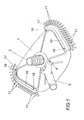
- einen erfindungsgemäßen Sauger für ein Schwimmbecken in einer vereinfachten perspektivischen Ansicht auf die Oberseite des Saugkopfes,
- Fig. 2
- eine perspektivische Ansicht auf die Unterseite des Saugkopfes,
- Fig. 3
- eine perspektivische Seitenansicht des Saugkopfes bei abgenommener, zum Teil aufgerissener Leiste und ausgezogenem Belastungsgewicht in einer Explosionsdarstellung und
- Fig. 4
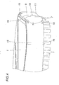
- eine perspektivische Darstellung des Saugkopfes im Bereich eines Seitenrandes ohne Leiste in einem größeren Maßstab.
- Fig. 1
- a suction device according to the invention for a swimming pool in a simplified perspective view of the top of the suction head,
- Fig. 2
- a perspective view of the underside of the suction head,
- Fig. 3
- a side perspective view of the suction head with removed, partially torn bar and pulled-load weight in an exploded view and
- Fig. 4
- a perspective view of the suction head in the region of a side edge without bar on a larger scale.
Der Sauger gemäß dem dargestellten Ausführungsbeispiel weist einen Saugkopf 1 aus Kunststoff auf, der einen Drehanschluß 2 für eine Saugleitung 3 trägt, wie sie in der
Wie insbesondere der
Neben diesen gegen die zu reinigende Beckenfläche gerichteten Borstenbündeln 7 sind an den bezüglich der Lagergabel 5 seitlichen Wänden 9 des Saugkopfes 1 Leisten 10 mit nach der Seite abgespreizten Borstenbündeln 11 vorgesehen, um das Ablösen von Verunreinigungen im Übergangsbereich, beispielsweise vom Beckenboden zu den Beckenwänden zu erleichtern. Diese mit Borstenbündel 11 besetzten Leisten 10 sind im Gegensatz zu Saugköpfen herkömmlicher Art lösbar mit dem Saugkopf 1 verbunden. Zu diesem Zweck bildet der Saugkopf 1 im Bereich der Seitenwände 9 für die Leisten 10 Längsführungen 12, die aus je einer Führungsnut 13 auf der an die Seitenwand 9 anschließenden Ober- und Unterseite des Saugkopfes 1 verlaufen und daher nach entgegengesetzten Seiten hin offen sind. In diese Führungsnuten 13 lassen sich in axialer Richtung entsprechende Halterungsstege 14 (
Zur Beschwerung des Saugkopfes 1 sind auf dessen Unterseite Aufnahmen 18 für Belastungsgewichte 19 vorgesehen. Diese Aufnahmen 18 bilden eine quer zu den Leisten 10 verlaufende Einsteckführung 20 für ein Belastungsgewicht 19. Da die Aufnahmen 18 ihre Einführöffnungen in den Seitenwänden 9 des Saugkopfes 1 haben (
Claims (4)
- Suction device for cleaning pools filled with a liquid, in particular swimming pools, comprising a suction head (1) which can be connected to a suction line (3) and via an articulated grip rod (4) can be moved along a surface of a pool to be cleaned and which suction head can be supported on the pool surface to be cleaned via bristle bundles (7) disposed in rows and supports strips (10) which are formed on the side possibly as a brush, characterised in that the lateral strips (10) are mounted in a removable manner in lateral longitudinal guides (12) of the suction head (1) and can be fixed in an axial manner by means of removable spring clips.
- Suction device as claimed in claim 1, characterised in that the longitudinal guides (12) consist in each case of two guide grooves (13) or guide webs which are disposed on mutually opposite suction head surfaces for guiding holding webs (14) or holding groves of the strips (10) which can be pushed thereon in an axial manner.
- Suction device as claimed in claim 1 or 2, characterised in that the suction head 1 comprises at least one receiving device (18) which is open towards the strips (10) and can be closed by this strip (10) for a loading weight (19).
- Suction device as claimed in claim 3 characterised in that the receiving device (18) for the loading weight (19) consists of an inserting guide (20) which extends transversely to the strip (10).
Priority Applications (1)
| Application Number | Priority Date | Filing Date | Title |
|---|---|---|---|
| AT02450013T ATE404762T1 (en) | 2001-02-22 | 2002-01-29 | VACUUM CLEANER FOR CLEANING POOLS FILLED WITH LIQUID, ESPECIALLY SWIMMING POOLS |
Applications Claiming Priority (2)
| Application Number | Priority Date | Filing Date | Title |
|---|---|---|---|
| AT0014301U AT5118U1 (en) | 2001-02-22 | 2001-02-22 | VACUUM CLEANER FOR CLEANING LIQUID-FILLED POOLS, IN PARTICULAR SWIMMING POOLS |
| AT2001143U | 2001-02-22 |
Publications (3)
| Publication Number | Publication Date |
|---|---|
| EP1234932A2 EP1234932A2 (en) | 2002-08-28 |
| EP1234932A3 EP1234932A3 (en) | 2003-11-05 |
| EP1234932B1 true EP1234932B1 (en) | 2008-08-13 |
Family
ID=3482649
Family Applications (1)
| Application Number | Title | Priority Date | Filing Date |
|---|---|---|---|
| EP02450013A Expired - Lifetime EP1234932B1 (en) | 2001-02-22 | 2002-01-29 | Sucker for cleaning a fluid filled container, specially a swimming pool |
Country Status (4)
| Country | Link |
|---|---|
| EP (1) | EP1234932B1 (en) |
| AT (2) | AT5118U1 (en) |
| DE (1) | DE50212620D1 (en) |
| ES (1) | ES2312542T3 (en) |
Families Citing this family (6)
| Publication number | Priority date | Publication date | Assignee | Title |
|---|---|---|---|---|
| BRPI0800553A2 (en) * | 2008-02-21 | 2009-10-06 | Helio Carlos Bartolon | elements and arrangement of elements for a pool bottom cleaner |
| FR2930797A1 (en) | 2008-04-30 | 2009-11-06 | Gatech Sarl | SWIMMING POOL CLEANING BRUSH |
| AT11975U1 (en) * | 2010-09-14 | 2011-08-15 | Edlmair Kunststofftechnik Gmbh | EQUIPMENT HEAD |
| US10100545B2 (en) * | 2013-03-15 | 2018-10-16 | Resh, Inc. | Vacuum head and hose apparatus and related methods |
| ME03478B (en) * | 2014-11-12 | 2020-01-20 | Crystal Lagoons Curacao Bv | Suctioning device for large artificial water bodies |
| US9920546B2 (en) | 2015-05-13 | 2018-03-20 | Zodiac Pool Systems Llc | Components of automatic pool cleaners |
Family Cites Families (3)
| Publication number | Priority date | Publication date | Assignee | Title |
|---|---|---|---|---|
| FR1105171A (en) * | 1953-12-02 | 1955-11-28 | Nautical vacuum cleaner intended for cleaning swimming pools | |
| CH552960A (en) * | 1973-08-20 | 1974-08-30 | Meyer Heinrich Bernhard | SOIL SUCTION BRUSH FOR SWIMMING POOL CLEANING. |
| CA1200955A (en) * | 1983-03-22 | 1986-02-25 | Heinz W. Braukmann | Vacuum head for cleaning underwater surfaces |
-
2001
- 2001-02-22 AT AT0014301U patent/AT5118U1/en not_active IP Right Cessation
-
2002
- 2002-01-29 EP EP02450013A patent/EP1234932B1/en not_active Expired - Lifetime
- 2002-01-29 DE DE50212620T patent/DE50212620D1/en not_active Expired - Lifetime
- 2002-01-29 AT AT02450013T patent/ATE404762T1/en active
- 2002-01-29 ES ES02450013T patent/ES2312542T3/en not_active Expired - Lifetime
Also Published As
| Publication number | Publication date |
|---|---|
| EP1234932A2 (en) | 2002-08-28 |
| ATE404762T1 (en) | 2008-08-15 |
| ES2312542T3 (en) | 2009-03-01 |
| AT5118U1 (en) | 2002-03-25 |
| EP1234932A3 (en) | 2003-11-05 |
| DE50212620D1 (en) | 2008-09-25 |
Similar Documents
| Publication | Publication Date | Title |
|---|---|---|
| DE69725735T2 (en) | WRING-OUT DEVICE FOR WIPER | |
| DE102005050805A1 (en) | Device for receiving bits | |
| DE10351536B4 (en) | Surface cleaning device | |
| EP1234932B1 (en) | Sucker for cleaning a fluid filled container, specially a swimming pool | |
| EP0937423B1 (en) | Rinsing brush | |
| DE102015112383B4 (en) | Container and cleaning kit | |
| EP0074525B1 (en) | Multi-purpose cleaning implement | |
| DE102020105490B4 (en) | shower shelf | |
| DE3605235C2 (en) | ||
| DE202009013659U1 (en) | Chain Cleaner | |
| DE102021112956B3 (en) | Bucket | |
| EP0900046B1 (en) | Cleaning unit | |
| EP2046179B1 (en) | Toilet brush | |
| DE2918716C2 (en) | Floor sweeper | |
| EP0570900A1 (en) | Cleaning cart | |
| EP1552779B1 (en) | Vacuum cleaner | |
| DE102021131862B4 (en) | Holder for hygiene products in the shower | |
| EP0085137B1 (en) | Water container for cover paint boxes | |
| DE2814434C2 (en) | Care cloth arranged in a protective cover | |
| DE19609964A1 (en) | Toothbrush holder | |
| DE202004018528U1 (en) | Toothbrush for cleaning teeth comprises a storage container, a handle with a brush head, a pump mechanism for conveying toothpaste from the container to the brush head and a device for equalizing the pressure in the container | |
| EP0109482A1 (en) | Toothbrush with a subdivided handle | |
| EP0015542A1 (en) | Bottle with pouring tube | |
| DE3243898C2 (en) | Rubber-elastic insert for a receiving vessel of a centrifuge | |
| DE8529619U1 (en) | Hand-held device for cleaning surfaces, in particular windows, in motor vehicles |
Legal Events
| Date | Code | Title | Description |
|---|---|---|---|
| PUAI | Public reference made under article 153(3) epc to a published international application that has entered the european phase |
Free format text: ORIGINAL CODE: 0009012 |
|
| AK | Designated contracting states |
Kind code of ref document: A2 Designated state(s): AT BE CH CY DE DK ES FI FR GB GR IE IT LI LU MC NL PT SE TR |
|
| AX | Request for extension of the european patent |
Free format text: AL;LT;LV;MK;RO;SI |
|
| PUAL | Search report despatched |
Free format text: ORIGINAL CODE: 0009013 |
|
| AK | Designated contracting states |
Kind code of ref document: A3 Designated state(s): AT BE CH CY DE DK ES FI FR GB GR IE IT LI LU MC NL PT SE TR |
|
| AX | Request for extension of the european patent |
Extension state: AL LT LV MK RO SI |
|
| 17P | Request for examination filed |
Effective date: 20031203 |
|
| AKX | Designation fees paid |
Designated state(s): AT BE CH CY DE DK ES FI FR GB GR IE IT LI LU MC NL PT SE TR |
|
| 17Q | First examination report despatched |
Effective date: 20061220 |
|
| GRAP | Despatch of communication of intention to grant a patent |
Free format text: ORIGINAL CODE: EPIDOSNIGR1 |
|
| GRAS | Grant fee paid |
Free format text: ORIGINAL CODE: EPIDOSNIGR3 |
|
| GRAA | (expected) grant |
Free format text: ORIGINAL CODE: 0009210 |
|
| AK | Designated contracting states |
Kind code of ref document: B1 Designated state(s): AT BE CH CY DE DK ES FI FR GB GR IE IT LI LU MC NL PT SE TR |
|
| REG | Reference to a national code |
Ref country code: GB Ref legal event code: FG4D Free format text: NOT ENGLISH |
|
| REG | Reference to a national code |
Ref country code: CH Ref legal event code: EP |
|
| REG | Reference to a national code |
Ref country code: IE Ref legal event code: FG4D Free format text: LANGUAGE OF EP DOCUMENT: GERMAN |
|
| REF | Corresponds to: |
Ref document number: 50212620 Country of ref document: DE Date of ref document: 20080925 Kind code of ref document: P |
|
| REG | Reference to a national code |
Ref country code: CH Ref legal event code: NV Representative=s name: E. BLUM & CO. AG PATENT- UND MARKENANWAELTE VSP |
|
| REG | Reference to a national code |
Ref country code: GR Ref legal event code: EP Ref document number: 20080403115 Country of ref document: GR |
|
| PG25 | Lapsed in a contracting state [announced via postgrant information from national office to epo] |
Ref country code: NL Free format text: LAPSE BECAUSE OF FAILURE TO SUBMIT A TRANSLATION OF THE DESCRIPTION OR TO PAY THE FEE WITHIN THE PRESCRIBED TIME-LIMIT Effective date: 20080813 |
|
| PG25 | Lapsed in a contracting state [announced via postgrant information from national office to epo] |
Ref country code: FI Free format text: LAPSE BECAUSE OF FAILURE TO SUBMIT A TRANSLATION OF THE DESCRIPTION OR TO PAY THE FEE WITHIN THE PRESCRIBED TIME-LIMIT Effective date: 20080813 |
|
| REG | Reference to a national code |
Ref country code: ES Ref legal event code: FG2A Ref document number: 2312542 Country of ref document: ES Kind code of ref document: T3 |
|
| REG | Reference to a national code |
Ref country code: IE Ref legal event code: FD4D |
|
| PG25 | Lapsed in a contracting state [announced via postgrant information from national office to epo] |
Ref country code: DK Free format text: LAPSE BECAUSE OF FAILURE TO SUBMIT A TRANSLATION OF THE DESCRIPTION OR TO PAY THE FEE WITHIN THE PRESCRIBED TIME-LIMIT Effective date: 20080813 Ref country code: IE Free format text: LAPSE BECAUSE OF FAILURE TO SUBMIT A TRANSLATION OF THE DESCRIPTION OR TO PAY THE FEE WITHIN THE PRESCRIBED TIME-LIMIT Effective date: 20080813 |
|
| PG25 | Lapsed in a contracting state [announced via postgrant information from national office to epo] |
Ref country code: PT Free format text: LAPSE BECAUSE OF FAILURE TO SUBMIT A TRANSLATION OF THE DESCRIPTION OR TO PAY THE FEE WITHIN THE PRESCRIBED TIME-LIMIT Effective date: 20090113 |
|
| PLBE | No opposition filed within time limit |
Free format text: ORIGINAL CODE: 0009261 |
|
| STAA | Information on the status of an ep patent application or granted ep patent |
Free format text: STATUS: NO OPPOSITION FILED WITHIN TIME LIMIT |
|
| 26N | No opposition filed |
Effective date: 20090514 |
|
| PG25 | Lapsed in a contracting state [announced via postgrant information from national office to epo] |
Ref country code: MC Free format text: LAPSE BECAUSE OF NON-PAYMENT OF DUE FEES Effective date: 20090131 Ref country code: IT Free format text: LAPSE BECAUSE OF FAILURE TO SUBMIT A TRANSLATION OF THE DESCRIPTION OR TO PAY THE FEE WITHIN THE PRESCRIBED TIME-LIMIT Effective date: 20080813 |
|
| GBPC | Gb: european patent ceased through non-payment of renewal fee |
Effective date: 20090129 |
|
| PG25 | Lapsed in a contracting state [announced via postgrant information from national office to epo] |
Ref country code: GB Free format text: LAPSE BECAUSE OF NON-PAYMENT OF DUE FEES Effective date: 20090129 |
|
| PG25 | Lapsed in a contracting state [announced via postgrant information from national office to epo] |
Ref country code: SE Free format text: LAPSE BECAUSE OF FAILURE TO SUBMIT A TRANSLATION OF THE DESCRIPTION OR TO PAY THE FEE WITHIN THE PRESCRIBED TIME-LIMIT Effective date: 20081113 |
|
| PG25 | Lapsed in a contracting state [announced via postgrant information from national office to epo] |
Ref country code: BE Free format text: LAPSE BECAUSE OF NON-PAYMENT OF DUE FEES Effective date: 20090131 |
|
| PGFP | Annual fee paid to national office [announced via postgrant information from national office to epo] |
Ref country code: CH Payment date: 20100129 Year of fee payment: 9 |
|
| PGFP | Annual fee paid to national office [announced via postgrant information from national office to epo] |
Ref country code: GR Payment date: 20100126 Year of fee payment: 9 |
|
| PG25 | Lapsed in a contracting state [announced via postgrant information from national office to epo] |
Ref country code: LU Free format text: LAPSE BECAUSE OF NON-PAYMENT OF DUE FEES Effective date: 20090129 |
|
| REG | Reference to a national code |
Ref country code: CH Ref legal event code: PL |
|
| PG25 | Lapsed in a contracting state [announced via postgrant information from national office to epo] |
Ref country code: CY Free format text: LAPSE BECAUSE OF FAILURE TO SUBMIT A TRANSLATION OF THE DESCRIPTION OR TO PAY THE FEE WITHIN THE PRESCRIBED TIME-LIMIT Effective date: 20080813 |
|
| PG25 | Lapsed in a contracting state [announced via postgrant information from national office to epo] |
Ref country code: LI Free format text: LAPSE BECAUSE OF NON-PAYMENT OF DUE FEES Effective date: 20110131 Ref country code: CH Free format text: LAPSE BECAUSE OF NON-PAYMENT OF DUE FEES Effective date: 20110131 |
|
| PG25 | Lapsed in a contracting state [announced via postgrant information from national office to epo] |
Ref country code: GR Free format text: LAPSE BECAUSE OF NON-PAYMENT OF DUE FEES Effective date: 20110802 |
|
| PGFP | Annual fee paid to national office [announced via postgrant information from national office to epo] |
Ref country code: ES Payment date: 20111205 Year of fee payment: 11 |
|
| PGFP | Annual fee paid to national office [announced via postgrant information from national office to epo] |
Ref country code: FR Payment date: 20120213 Year of fee payment: 11 |
|
| PGFP | Annual fee paid to national office [announced via postgrant information from national office to epo] |
Ref country code: TR Payment date: 20120123 Year of fee payment: 11 |
|
| PGFP | Annual fee paid to national office [announced via postgrant information from national office to epo] |
Ref country code: AT Payment date: 20120104 Year of fee payment: 11 |
|
| REG | Reference to a national code |
Ref country code: AT Ref legal event code: MM01 Ref document number: 404762 Country of ref document: AT Kind code of ref document: T Effective date: 20130131 |
|
| REG | Reference to a national code |
Ref country code: FR Ref legal event code: ST Effective date: 20130930 |
|
| PG25 | Lapsed in a contracting state [announced via postgrant information from national office to epo] |
Ref country code: AT Free format text: LAPSE BECAUSE OF NON-PAYMENT OF DUE FEES Effective date: 20130131 |
|
| PG25 | Lapsed in a contracting state [announced via postgrant information from national office to epo] |
Ref country code: FR Free format text: LAPSE BECAUSE OF NON-PAYMENT OF DUE FEES Effective date: 20130131 |
|
| PGFP | Annual fee paid to national office [announced via postgrant information from national office to epo] |
Ref country code: DE Payment date: 20140110 Year of fee payment: 13 |
|
| REG | Reference to a national code |
Ref country code: ES Ref legal event code: FD2A Effective date: 20140509 |
|
| PG25 | Lapsed in a contracting state [announced via postgrant information from national office to epo] |
Ref country code: ES Free format text: LAPSE BECAUSE OF NON-PAYMENT OF DUE FEES Effective date: 20130130 |
|
| REG | Reference to a national code |
Ref country code: DE Ref legal event code: R119 Ref document number: 50212620 Country of ref document: DE |
|
| PG25 | Lapsed in a contracting state [announced via postgrant information from national office to epo] |
Ref country code: TR Free format text: LAPSE BECAUSE OF NON-PAYMENT OF DUE FEES Effective date: 20130129 |
|
| PG25 | Lapsed in a contracting state [announced via postgrant information from national office to epo] |
Ref country code: DE Free format text: LAPSE BECAUSE OF NON-PAYMENT OF DUE FEES Effective date: 20150801 |