EP1234932A2 - Sucker for cleaning a fluid filled container, specially a swimming pool - Google Patents
Sucker for cleaning a fluid filled container, specially a swimming pool Download PDFInfo
- Publication number
- EP1234932A2 EP1234932A2 EP02450013A EP02450013A EP1234932A2 EP 1234932 A2 EP1234932 A2 EP 1234932A2 EP 02450013 A EP02450013 A EP 02450013A EP 02450013 A EP02450013 A EP 02450013A EP 1234932 A2 EP1234932 A2 EP 1234932A2
- Authority
- EP
- European Patent Office
- Prior art keywords
- suction head
- strips
- suction
- bar
- guide
- Prior art date
- Legal status (The legal status is an assumption and is not a legal conclusion. Google has not performed a legal analysis and makes no representation as to the accuracy of the status listed.)
- Granted
Links
- 230000009182 swimming Effects 0.000 title claims abstract description 7
- 238000004140 cleaning Methods 0.000 title claims abstract description 6
- 239000012530 fluid Substances 0.000 title 1
- 238000003780 insertion Methods 0.000 claims description 5
- 230000037431 insertion Effects 0.000 claims description 5
- 239000007788 liquid Substances 0.000 claims description 3
- XLYOFNOQVPJJNP-UHFFFAOYSA-N water Substances O XLYOFNOQVPJJNP-UHFFFAOYSA-N 0.000 abstract description 2
- 239000000356 contaminant Substances 0.000 description 2
- 239000012535 impurity Substances 0.000 description 2
- 210000003903 pelvic floor Anatomy 0.000 description 2
- 230000007704 transition Effects 0.000 description 2
- 241000252169 Catostomus commersonii Species 0.000 description 1
- 230000015572 biosynthetic process Effects 0.000 description 1
- 238000010276 construction Methods 0.000 description 1
- 230000008878 coupling Effects 0.000 description 1
- 238000010168 coupling process Methods 0.000 description 1
- 238000005859 coupling reaction Methods 0.000 description 1
- 238000006073 displacement reaction Methods 0.000 description 1
- ZINJLDJMHCUBIP-UHFFFAOYSA-N ethametsulfuron-methyl Chemical compound CCOC1=NC(NC)=NC(NC(=O)NS(=O)(=O)C=2C(=CC=CC=2)C(=O)OC)=N1 ZINJLDJMHCUBIP-UHFFFAOYSA-N 0.000 description 1
- 230000002349 favourable effect Effects 0.000 description 1
- 239000000463 material Substances 0.000 description 1
- 239000002184 metal Substances 0.000 description 1
- 210000004197 pelvis Anatomy 0.000 description 1
- 230000001681 protective effect Effects 0.000 description 1
Images

Classifications
-
- E—FIXED CONSTRUCTIONS
- E04—BUILDING
- E04H—BUILDINGS OR LIKE STRUCTURES FOR PARTICULAR PURPOSES; SWIMMING OR SPLASH BATHS OR POOLS; MASTS; FENCING; TENTS OR CANOPIES, IN GENERAL
- E04H4/00—Swimming or splash baths or pools
- E04H4/14—Parts, details or accessories not otherwise provided for
- E04H4/16—Parts, details or accessories not otherwise provided for specially adapted for cleaning
- E04H4/1618—Hand-held powered cleaners
- E04H4/1636—Suction cleaners
-
- E—FIXED CONSTRUCTIONS
- E04—BUILDING
- E04H—BUILDINGS OR LIKE STRUCTURES FOR PARTICULAR PURPOSES; SWIMMING OR SPLASH BATHS OR POOLS; MASTS; FENCING; TENTS OR CANOPIES, IN GENERAL
- E04H4/00—Swimming or splash baths or pools
- E04H4/14—Parts, details or accessories not otherwise provided for
- E04H4/16—Parts, details or accessories not otherwise provided for specially adapted for cleaning
- E04H4/1618—Hand-held powered cleaners
Definitions
- the invention relates to a vacuum cleaner for cleaning with liquid filled pools, in particular swimming pools, with a suction line connectable, via an articulated handle along one to be cleaned Suction head that can be moved around the pelvis, the bristle bundle arranged in rows can be supported on the pool surface to be cleaned and lateral, if necessary lasts trained as a brush.
- suction cups that can be connected to a suction line Suction head exist, the one protruding in rows against the pelvic floor Bunches of bristles.
- a hinged handlebar suction head to be guided is supported by these bristle bundles on the pool floor, the one with a movement of the suction head over the pelvic floor for one Detach the contaminants deposited on the pool floor and on the other hand the removal of the loosened impurities by the formation of Support flow channels between the bristle bundles arranged in rows.
- the suction head supports the handlebar linkage Lateral bristle bundle rows in the form of strips, the removal of contaminants in the transition area from the pool floor to lighten the pool walls.
- the invention is therefore based on the object of a vacuum cleaner for cleaning of pools filled with liquid, especially swimming pools, at the beginning to be described in such a way that the service life can be increased.
- advantageous design requirements are to be created, to easily adjust the weight of the suction head to the respective Allow requirements.
- the invention solves the problem in that the side strips extendable stored in lateral longitudinal guides of the suction head and by removable Spring catches are fixed axially.
- the Longitudinal guides each consisting of two suction head surfaces located opposite one another arranged guide grooves or guide bars for axially slidable mounting bars or mounting grooves of the strips. Because the guide grooves on opposing suction head surfaces are arranged, the axial in these guide grooves inserted support webs of the strips across Longitudinal direction of the guide grooves held positively in the suction head, so that the Bracket of the strips essentially depends on the strength of the support bars.
- the same constructive advantages are obtained if the function is reversed not the suction head, but the strips are provided with mounting grooves, then engage in the guide webs of the suction head.
- the strips that can be used in the longitudinal longitudinal guides of the suction head offer not only advantageous mounting conditions for the interchangeable strips, but also pose an essential requirement for a simple interchangeable Inclusion of load weights.
- the suction head is at least one open to and from a ledge
- a lockable receptacle for a load weight so that the load weight with the bar removed in the holder of the suction head can be used to then when inserting the bar into its longitudinal guide close the receptacle securely.
- the load on the bar by the Load weight inserted into the receptacle is transverse to the longitudinal guide of the strips, so that this loading of the strips without danger to the strip holder can be removed on the suction head.
- the sucker has one Suction head 1 made of plastic, which has a rotary connection 2 for a suction line 3rd bears, as indicated by dash-dotted lines in Fig. 3.
- a handle bar 4 which has a plug-in coupling with one on the suction head 1 articulated storage fork 5 is connectable.
- the pivot axis of this fork 5 is designated by 6.
- bristle bundle 7 are on the underside of the suction head 1 projecting against the pool surface to be cleaned bristle bundle 7 provided, through which the suction head 1 is to be cleaned Supports the pelvic area.
- These bristle bundles 7 are arranged in rows, which the Take over function of guide walls for the water flow through the suction opening 8 of the rotary connector 2 for the suction line 4 are sucked.
- strips 10 are provided with bristle bundles 11 spread to the side, to remove impurities in the transition area, for example from the pool floor to the pool walls.
- bristle bundles 11 spread to the side, to remove impurities in the transition area, for example from the pool floor to the pool walls.
- 11 occupied strips 10 can be detached connected to the suction head 1.
- the suction head 1 forms Area of the side walls 9 for the strips 10 longitudinal guides 12, each of one Guide groove 13 on the upper and lower side adjoining the side wall 9 of the suction head 1 and therefore open towards opposite sides are.
- this guide grooves 13 can be corresponding in the axial direction Insert support webs 14 (Fig.
- the side walls 9 have locking bodies 15, which snap-lock-like in recesses 16 of the strips 10 intervene when the strips 10 are inserted into the longitudinal guide 12.
- the strips 10 are extended beyond the longitudinal guide 12 to the front
- the strip 10 is bent in this End section 17 also locked, again using a resilient locking body 15 on the suction head 1 and a locking recess in the end portion 17 of the bar 10.
Landscapes
- Engineering & Computer Science (AREA)
- Architecture (AREA)
- Civil Engineering (AREA)
- Structural Engineering (AREA)
- Nozzles For Electric Vacuum Cleaners (AREA)
- Cleaning In General (AREA)
Abstract
Description
Die Erfindung bezieht sich auf einen Sauger zum Reinigen von mit Flüssigkeit gefüllten Becken, insbesondere Schwimmbecken, mit einem an eine Saugleitung anschließbaren, über eine angelenkte Griffstange entlang einer zu reinigenden Beckenfläche bewegbaren Saugkopf, der über reihenweise angeordnete Borstenbündel an der zu reinigenden Beckenfläche abstützbar ist und seitliche, gegebenenfalls als Bürste ausgebildete Leisten trägt.The invention relates to a vacuum cleaner for cleaning with liquid filled pools, in particular swimming pools, with a suction line connectable, via an articulated handle along one to be cleaned Suction head that can be moved around the pelvis, the bristle bundle arranged in rows can be supported on the pool surface to be cleaned and lateral, if necessary lasts trained as a brush.
Zum Reinigen des Bodens und der Wände eines Schwimmbeckens ist es bekannt, Sauger einzusetzen, die aus einem, an eine Saugleitung anschließbaren Saugkopf bestehen, der gegen den Beckenboden vorstehende, reihenweise angeordnete Borstenbündel trägt. Der über eine angelenkte Griffstange von Hand aus zu führende Saugkopf stützt sich über diese Borstenbündel am Beckenboden ab, die bei einer Bewegung des Saugkopfes über den Beckenboden einerseits für ein Ablösen der am Beckenboden abgelagerten Verunreinigungen sorgen und anderseits die Absaugung der abgelösten Verunreinigungen durch die Ausbildung von Strömungskanälen zwischen den reihenweise angeordneten Borstenbündeln unterstützen. Zusätzlich trägt der Saugkopf an den bezüglich der Griffstangenanlenkung seitlichen Rändern seitlich abstehende Borstenbündelreihen in Form von Leisten, die das Abtragen von Verunreinigungen im Übergangsbereich vom Beckenboden zu den Beckenwänden erleichtern sollen. Diese seitlichen Leisten unterliegen im allgemeinen einem größeren Verschleiß als die gegen den Boden gerichteten Borsten und bestimmen daher im wesentlichen die Standzeit solcher Saugköpfe. Dazu kommt, daß solche Saugköpfe durch Belastungsgewichte beschwert werden, um einen ausreichenden Anpreßdruck der Borsten an den Boden sicherstellen zu können, ohne diesen Anpreßdruck von Hand aus über die Griffstange aufbringen zu müssen. Diese Belastungsgewichte werden in Aufnahmen überwiegend auf der Unterseite des Saugkopfes vorgesehen, wobei die Aufnahmen durch einen angeklebten oder angeschweißten Deckel abgeschlossen sind, um die Belastungsgewichte dem Saugkopf unverlierbar zuzuordnen. Dieser dauerhafte Verschluß bringt allerdings den Nachteil mit sich, daß die Belastungsgewichte von vornherein festgelegt werden müssen. Außerdem ist eine nach Werkstoffen getrennte Entsorgung solcher Saugköpfe kaum möglich, weil der Saugkopf mit den Borstenbündeln aus Kunststoff, die Belastungsgewichte aber im allgemeinen aus Metall bestehen.It is for cleaning the floor and walls of a swimming pool known to use suction cups that can be connected to a suction line Suction head exist, the one protruding in rows against the pelvic floor Bunches of bristles. By hand using a hinged handlebar suction head to be guided is supported by these bristle bundles on the pool floor, the one with a movement of the suction head over the pelvic floor for one Detach the contaminants deposited on the pool floor and on the other hand the removal of the loosened impurities by the formation of Support flow channels between the bristle bundles arranged in rows. In addition, the suction head supports the handlebar linkage Lateral bristle bundle rows in the form of strips, the removal of contaminants in the transition area from the pool floor to lighten the pool walls. These side strips are subject to generally more wear than those against the ground Bristles and therefore essentially determine the service life of such suction heads. In addition, such suction heads are weighed down by load weights to ensure that the bristles are sufficiently pressed against the ground to be able to use the handlebar without this pressure to have to muster. These load weights are predominant in recordings provided on the underside of the suction head, the recordings by a glued or welded lid are completed to support the load weights assignable to the suction head. This permanent closure has the disadvantage, however, that the load weights of must be determined in advance. In addition, one is separated according to materials Disposal of such suction heads is hardly possible because the suction head with the Bristle bundles made of plastic, but the load weights in general Metal.
Der Erfindung liegt somit die Aufgabe zugrunde, einen Sauger zum Reinigen von mit Flüssigkeit gefüllten Becken, insbesondere Schwimmbecken, der eingangs geschilderten Art so auszugestalten, daß die Standzeit erhöht werden kann. Außerdem sollen vorteilhafte Konstruktionsvoraussetzungen geschaffen werden, um eine einfache Anpassung der Gewichtsbelastung des Saugkopfes an die jeweiligen Anforderungen zu ermöglichen.The invention is therefore based on the object of a vacuum cleaner for cleaning of pools filled with liquid, especially swimming pools, at the beginning to be described in such a way that the service life can be increased. In addition, advantageous design requirements are to be created, to easily adjust the weight of the suction head to the respective Allow requirements.
Die Erfindung löst die gestellte Aufgabe dadurch, daß die seitlichen Leisten ausziehbar in seitlichen Längsführungen des Saugkopfes gelagert und durch lösbare Federrasten axial festgelegt sind.The invention solves the problem in that the side strips extendable stored in lateral longitudinal guides of the suction head and by removable Spring catches are fixed axially.
Das durch diese Lagerung der Leisten mögliche Auswechseln dieser Leisten erlaubt zunächst beim Einsatz von mit Bürstenborsten besetzten Leisten den Ersatz verschlissener Bürstenleisten durch unverschlissene, so daß die Standzeit des gesamten Saugkopfes nicht mehr durch die Standzeit dieser mit Borstenbündeln besetzten Leisten begrenzt wird. Trotz dieser Auswechselbarkeit wird eine allen Anforderungen genügende Halterung der Leisten am Saugkopf erreicht, weil durch die Aufnahme der Leisten in seitlichen Längsführungen des Saugkopfes eine über diese Längsführungen durchgehende Abstützung der Leisten gewährleistet werden kann, ohne eine Beeinträchtigung der Anordnung der Borstenbündel oder eine Vergrößerung der Leistenabmessungen befürchten zu müssen. Da die Leisten innerhalb der Längsführungen durch lösbare Federrasten festgelegt werden, ist auch die Befestigung der Leisten am Saugkopf bzw. das Abnehmen der Leisten denkbar einfach. Werden die Leisten als Schutzleisten ohne einen Bürstenbesatz ausgebildet, so ergeben sich ähnliche Vorteile hinsichtlich der Auswechselbarkeit verschlissener Leisten. The possible replacement of these strips by this storage of the strips initially allows the use of strips with brush bristles Replacement of worn brush strips with uns worn ones, so that the service life the entire suction head no longer due to the service life of these with bristle bundles occupied lasts is limited. Despite this interchangeability achieved all the requirements of holding the strips on the suction head because through the inclusion of the strips in the lateral longitudinal guides of the suction head Continuous support of the strips is ensured via these longitudinal guides can be without affecting the arrangement of the bristle bundle or have to fear an increase in the bar dimensions. Because the lasts can be fixed within the longitudinal guides by releasable spring catches, is also the attachment of the strips to the suction head or the removal of the strips very easy. Are the strips as protective strips without a brush trim trained, there are similar advantages in terms of interchangeability worn out lasts.
Besonders vorteilhafte Konstruktionsverhältnisse ergeben sich, wenn die Längsführungen aus je zwei auf einander gegenüberliegenden Saugkopfflächen angeordneten Führungsnuten oder Führungsstegen für axial aufschiebbare Halterungsstege oder Halterungsnuten der Leisten bestehen. Da die Führungsnuten auf einander gegenüberliegenden Saugkopfflächen angeordnet sind, werden die axial in diese Führungsnuten eingeschobenen Halterungsstege der Leisten quer zur Längsrichtung der Führungsnuten formschlüssig im Saugkopf gehalten, so daß die Halterung der Leisten im wesentlichen von der Festigkeit der Halterungsstege abhängt. Gleiche konstruktive Vorteile werden erhalten, wenn in einer Funktionsumkehr nicht der Saugkopf, sondern die Leisten mit Halterungsnuten versehen werden, in die dann Führungsstege des Saugkopfes eingreifen.Particularly advantageous design relationships arise when the Longitudinal guides each consisting of two suction head surfaces located opposite one another arranged guide grooves or guide bars for axially slidable mounting bars or mounting grooves of the strips. Because the guide grooves on opposing suction head surfaces are arranged, the axial in these guide grooves inserted support webs of the strips across Longitudinal direction of the guide grooves held positively in the suction head, so that the Bracket of the strips essentially depends on the strength of the support bars. The same constructive advantages are obtained if the function is reversed not the suction head, but the strips are provided with mounting grooves, then engage in the guide webs of the suction head.
Die in seitliche Längsführungen des Saugkopfes einsetzbaren Leisten bieten nicht nur vorteilhafte Halterungsbedingungen für die auswechselbaren Leisten, sondern stellen auch eine wesentliche Voraussetzung für eine einfache auswechselbare Aufnahme von Belastungsgewichten dar. Zu diesem Zweck braucht ja lediglich der Saugkopf wenigstens eine gegen eine Leiste hin offene und von dieser Leiste verschließbare Aufnahme für ein Belastungsgewicht aufzuweisen, so daß das Belastungsgewicht bei abgenommener Leiste in die Aufnahme des Saugkopfes eingesetzt werden kann, um dann beim Einschieben der Leiste in ihre Längsführung die Aufnahme sicher zu verschließen. Die Belastung der Leiste durch das in die Aufnahme eingeschobene Belastungsgewicht erfolgt quer zur Längsführung der Leisten, so daß diese Belastung der Leisten ohne Gefahr für die Leistenhalterung auf den Saugkopf abgetragen werden kann. Besonders günstige Konstruktionsbedingungen können in diesem Zusammenhang eingehalten werden, wenn die Aufnahme aus einer quer zur Leiste verlaufenden Einsteckführung für ein Belastungsgewicht besteht. Durch diese Maßnahme wird der Saugkopf im Bereich der Längsführung der Leisten durch die stirnseitige Öffnung der Aufnahme kaum geschwächt.The strips that can be used in the longitudinal longitudinal guides of the suction head offer not only advantageous mounting conditions for the interchangeable strips, but also pose an essential requirement for a simple interchangeable Inclusion of load weights. For this purpose only needs the suction head is at least one open to and from a ledge To have a lockable receptacle for a load weight, so that the load weight with the bar removed in the holder of the suction head can be used to then when inserting the bar into its longitudinal guide close the receptacle securely. The load on the bar by the Load weight inserted into the receptacle is transverse to the longitudinal guide of the strips, so that this loading of the strips without danger to the strip holder can be removed on the suction head. Particularly favorable construction conditions can be observed in this context if the Mounted from an insertion guide running across the bar for a load weight consists. By this measure, the suction head in the area Longitudinal guiding of the strips is hardly weakened by the front opening of the holder.
In der Zeichnung ist der Erfindungsgegenstand beispielsweise dargestellt.The subject matter of the invention is shown in the drawing, for example.
Es zeigen
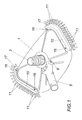
- Fig. 1
- einen erfindungsgemäßen Sauger für ein Schwimmbecken in einer vereinfachten perspektivischen Ansicht auf die Oberseite des Saugkopfes,
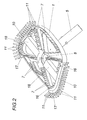
- Fig. 2
- eine perspektivische Ansicht auf die Unterseite des Saugkopfes,
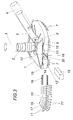
- Fig. 3
- eine perspektivische Seitenansicht des Saugkopfes bei abgenommener, zum Teil aufgerissener Leiste und ausgezogenem Belastungsgewicht in einer Explosionsdarstellung und
- Fig. 4
- eine perspektivische Darstellung des Saugkopfes im Bereich eines Seitenrandes ohne Leiste in einem größeren Maßstab.
- Fig. 1
- a vacuum cleaner according to the invention for a swimming pool in a simplified perspective view of the top of the suction head,
- Fig. 2
- a perspective view of the underside of the suction head,
- Fig. 3
- a side perspective view of the suction head with removed, partially torn strip and extended load weight in an exploded view and
- Fig. 4
- a perspective view of the suction head in the area of a side edge without a bar on a larger scale.
Der Sauger gemäß dem dargestellten Ausführungsbeispiel weist einen
Saugkopf 1 aus Kunststoff auf, der einen Drehanschluß 2 für eine Saugleitung 3
trägt, wie sie in der Fig. 3 strichpunktiert angedeutet ist. Zur Führung dieses Saugkopfes
1 dient eine Griffstange 4, die über eine Steckkupplung mit einer am Saugkopf
1 angelenkten Lagergabel 5 verbindbar ist. Die Anlenkachse dieser Lagergabel
5 ist mit 6 bezeichnet.The sucker according to the illustrated embodiment has one
Wie insbesondere der Fig. 2 entnommen werden kann, sind auf der Unterseite
des Saugkopfes 1 gegen die zu reinigende Beckenfläche vorstehende Borstenbündel
7 vorgesehen, über die sich der Saugkopf 1 an der zu reinigenden
Beckenfläche abstützt. Diese Borstenbündel 7 sind in Reihen angeordnet, die die
Funktion von Leitwänden für die Wasserströmung übernehmen, die durch die Saugöffnung
8 des Drehanschlusses 2 für die Saugleitung 4 angesaugt werden.As can be seen in particular from FIG. 2, are on the underside
of the
Neben diesen gegen die zu reinigende Beckenfläche gerichteten Borstenbündeln
7 sind an den bezüglich der Lagergabel 5 seitlichen Wänden 9 des Saugkopfes
1 Leisten 10 mit nach der Seite abgespreizten Borstenbündeln 11 vorgesehen,
um das Ablösen von Verunreinigungen im Übergangsbereich, beispielsweise
vom Beckenboden zu den Beckenwänden zu erleichtern. Diese mit Borstenbündel
11 besetzten Leisten 10 sind im Gegensatz zu Saugköpfen herkömmlicher Art lösbar
mit dem Saugkopf 1 verbunden. Zu diesem Zweck bildet der Saugkopf 1 im
Bereich der Seitenwände 9 für die Leisten 10 Längsführungen 12, die aus je einer
Führungsnut 13 auf der an die Seitenwand 9 anschließenden Ober- und Unterseite
des Saugkopfes 1 verlaufen und daher nach entgegengesetzten Seiten hin offen
sind. In diese Führungsnuten 13 lassen sich in axialer Richtung entsprechende
Halterungsstege 14 (Fig. 3) einschieben, so daß die Leisten 10 in der Längsführung
12 eine formschlüssige Halterung finden, die lediglich gegen ein axiales Verschieben
der Leisten 10 zu sichern ist. Hiefür weisen die Seitenwände 9 Rastkörper
15 auf, die in Rastausnehmungen 16 der Leisten 10 schnappverschlußartig
eingreifen, wenn die Leisten 10 in die Längsführung 12 eingeschoben werden. Da
die Leisten 10 über die Längsführung 12 hinaus verlängert sind, um den vorderen
Eckbereich des Saugkopfes 1 zu übergreifen, wird die Leiste 10 in diesem gebogenen
Endabschnitt 17 zusätzlich verrastet, und zwar wiederum mit Hilfe eines
federnden Rastkörpers 15 auf dem Saugkopf 1 und einer Rastausnehmung im Endabschnitt
17 der Leiste 10.In addition to these bristle bundles directed against the pool surface to be cleaned
7 are on the
Zur Beschwerung des Saugkopfes 1 sind auf dessen Unterseite Aufnahmen
18 für Belastungsgewichte 19 vorgesehen. Diese Aufnahmen 18 bilden eine quer
zu den Leisten 10 verlaufende Einsteckführung 20 für ein Belastungsgewicht 19.
Da die Aufnahmen 18 ihre Einführöffnungen in den Seitenwänden 9 des Saugkopfes
1 haben (Fig. 3), werden diese Aufnahmen 18 durch die in die Längsführungen
12 eingesetzten Leisten 10 verschlossen, was eine sichere Halterung der
Belastungsgewichte 19 innerhalb der Einsteckführungen 20 mit sich bringt. Bei abgenommener
Leiste 10 kann das Belastungsgewicht 19 allerdings entnommen und
beispielsweise durch ein Belastungsgewicht unterschiedlicher Größe ersetzt werden.To weigh down the
Claims (4)
Priority Applications (1)
| Application Number | Priority Date | Filing Date | Title |
|---|---|---|---|
| AT02450013T ATE404762T1 (en) | 2001-02-22 | 2002-01-29 | VACUUM CLEANER FOR CLEANING POOLS FILLED WITH LIQUID, ESPECIALLY SWIMMING POOLS |
Applications Claiming Priority (2)
| Application Number | Priority Date | Filing Date | Title |
|---|---|---|---|
| AT0014301U AT5118U1 (en) | 2001-02-22 | 2001-02-22 | VACUUM CLEANER FOR CLEANING LIQUID-FILLED POOLS, IN PARTICULAR SWIMMING POOLS |
| AT2001143U | 2001-02-22 |
Publications (3)
| Publication Number | Publication Date |
|---|---|
| EP1234932A2 true EP1234932A2 (en) | 2002-08-28 |
| EP1234932A3 EP1234932A3 (en) | 2003-11-05 |
| EP1234932B1 EP1234932B1 (en) | 2008-08-13 |
Family
ID=3482649
Family Applications (1)
| Application Number | Title | Priority Date | Filing Date |
|---|---|---|---|
| EP02450013A Expired - Lifetime EP1234932B1 (en) | 2001-02-22 | 2002-01-29 | Sucker for cleaning a fluid filled container, specially a swimming pool |
Country Status (4)
| Country | Link |
|---|---|
| EP (1) | EP1234932B1 (en) |
| AT (2) | AT5118U1 (en) |
| DE (1) | DE50212620D1 (en) |
| ES (1) | ES2312542T3 (en) |
Cited By (6)
| Publication number | Priority date | Publication date | Assignee | Title |
|---|---|---|---|---|
| WO2009103141A1 (en) * | 2008-02-21 | 2009-08-27 | Helio Carlos Bortolon | Vacuum head for a pool cleaner |
| WO2009133327A2 (en) | 2008-04-30 | 2009-11-05 | Gatech | Swimming pool cleaning brush |
| EP2428150A1 (en) * | 2010-09-14 | 2012-03-14 | Edlmair Kunststofftechnik GmbH | Suction head for suction cleaning apparatus |
| US20170241149A1 (en) * | 2015-05-13 | 2017-08-24 | Zodiac Pool Systems, Inc. | Components of automatic pool cleaners |
| EP3217854A4 (en) * | 2014-11-12 | 2018-07-11 | Crystal Lagoons (Curaçao) B.V. | Suctioning device for large artificial water bodies |
| US10982457B2 (en) * | 2013-03-15 | 2021-04-20 | Resh, Inc. | Vacuum head and hose apparatus and related methods |
Family Cites Families (3)
| Publication number | Priority date | Publication date | Assignee | Title |
|---|---|---|---|---|
| FR1105171A (en) * | 1953-12-02 | 1955-11-28 | Nautical vacuum cleaner intended for cleaning swimming pools | |
| CH552960A (en) * | 1973-08-20 | 1974-08-30 | Meyer Heinrich Bernhard | SOIL SUCTION BRUSH FOR SWIMMING POOL CLEANING. |
| CA1200955A (en) * | 1983-03-22 | 1986-02-25 | Heinz W. Braukmann | Vacuum head for cleaning underwater surfaces |
-
2001
- 2001-02-22 AT AT0014301U patent/AT5118U1/en not_active IP Right Cessation
-
2002
- 2002-01-29 EP EP02450013A patent/EP1234932B1/en not_active Expired - Lifetime
- 2002-01-29 DE DE50212620T patent/DE50212620D1/en not_active Expired - Lifetime
- 2002-01-29 ES ES02450013T patent/ES2312542T3/en not_active Expired - Lifetime
- 2002-01-29 AT AT02450013T patent/ATE404762T1/en active
Non-Patent Citations (1)
| Title |
|---|
| None |
Cited By (12)
| Publication number | Priority date | Publication date | Assignee | Title |
|---|---|---|---|---|
| WO2009103141A1 (en) * | 2008-02-21 | 2009-08-27 | Helio Carlos Bortolon | Vacuum head for a pool cleaner |
| WO2009133327A2 (en) | 2008-04-30 | 2009-11-05 | Gatech | Swimming pool cleaning brush |
| FR2930797A1 (en) * | 2008-04-30 | 2009-11-06 | Gatech Sarl | SWIMMING POOL CLEANING BRUSH |
| WO2009133327A3 (en) * | 2008-04-30 | 2009-12-23 | Gatech | Swimming pool cleaning brush |
| EP2428150A1 (en) * | 2010-09-14 | 2012-03-14 | Edlmair Kunststofftechnik GmbH | Suction head for suction cleaning apparatus |
| US10982457B2 (en) * | 2013-03-15 | 2021-04-20 | Resh, Inc. | Vacuum head and hose apparatus and related methods |
| US20210332602A1 (en) * | 2013-03-15 | 2021-10-28 | Eric V. Resh | Vacuum head and hose apparatus and related methods |
| US11773615B2 (en) * | 2013-03-15 | 2023-10-03 | Resh, Inc. | Vacuum head and hose apparatus and related methods |
| EP3217854A4 (en) * | 2014-11-12 | 2018-07-11 | Crystal Lagoons (Curaçao) B.V. | Suctioning device for large artificial water bodies |
| US20170241149A1 (en) * | 2015-05-13 | 2017-08-24 | Zodiac Pool Systems, Inc. | Components of automatic pool cleaners |
| US10428546B2 (en) * | 2015-05-13 | 2019-10-01 | Zodiac Pool Systems Llc | Components of automatic pool cleaners |
| US10480205B2 (en) | 2015-05-13 | 2019-11-19 | Zodiac Pool Systems Llc | Components of automatic pool cleaners |
Also Published As
| Publication number | Publication date |
|---|---|
| EP1234932B1 (en) | 2008-08-13 |
| ATE404762T1 (en) | 2008-08-15 |
| DE50212620D1 (en) | 2008-09-25 |
| ES2312542T3 (en) | 2009-03-01 |
| AT5118U1 (en) | 2002-03-25 |
| EP1234932A3 (en) | 2003-11-05 |
Similar Documents
| Publication | Publication Date | Title |
|---|---|---|
| DE69502841T2 (en) | Cleaning device | |
| EP1481625B1 (en) | Floor cleaning machine and dirt container for such a floor cleaning machine | |
| DE20205632U1 (en) | secateurs | |
| EP1234932B1 (en) | Sucker for cleaning a fluid filled container, specially a swimming pool | |
| EP0937423B1 (en) | Rinsing brush | |
| EP0074525A1 (en) | Multi-purpose cleaning implement | |
| DE3605235C2 (en) | ||
| DE102015112383B4 (en) | Container and cleaning kit | |
| EP0570900A1 (en) | Cleaning cart | |
| DD266962A5 (en) | HANDLE BROOM | |
| EP1188406B1 (en) | Mop | |
| DE202009013659U1 (en) | Chain Cleaner | |
| DE19609964C2 (en) | Toothbrush with holder | |
| DE102013106951A1 (en) | Staubsaugerbodendüse | |
| DE2905554A1 (en) | MULTI-PURPOSE CLEANER MOUTH PIECE | |
| EP1552779B1 (en) | Vacuum cleaner | |
| DE10362035B4 (en) | Broom, broom and hand brush | |
| DE9113769U1 (en) | toothbrush | |
| DE3801817C2 (en) | ||
| DE8910724U1 (en) | Attachment sweeper | |
| DE3002419A1 (en) | DEVICE FOR RECEIVING DENTAL PRODUCTS | |
| DE8503755U1 (en) | Toothbrush with storage chamber for dentifrice | |
| DE8716748U1 (en) | Cleaning head for hard surfaces | |
| DE29719879U1 (en) | Toothbrush tumbler | |
| DE202021100645U1 (en) | Squeegee element and article with a squeegee element, and use of a squeegee element |
Legal Events
| Date | Code | Title | Description |
|---|---|---|---|
| PUAI | Public reference made under article 153(3) epc to a published international application that has entered the european phase |
Free format text: ORIGINAL CODE: 0009012 |
|
| AK | Designated contracting states |
Kind code of ref document: A2 Designated state(s): AT BE CH CY DE DK ES FI FR GB GR IE IT LI LU MC NL PT SE TR |
|
| AX | Request for extension of the european patent |
Free format text: AL;LT;LV;MK;RO;SI |
|
| PUAL | Search report despatched |
Free format text: ORIGINAL CODE: 0009013 |
|
| AK | Designated contracting states |
Kind code of ref document: A3 Designated state(s): AT BE CH CY DE DK ES FI FR GB GR IE IT LI LU MC NL PT SE TR |
|
| AX | Request for extension of the european patent |
Extension state: AL LT LV MK RO SI |
|
| 17P | Request for examination filed |
Effective date: 20031203 |
|
| AKX | Designation fees paid |
Designated state(s): AT BE CH CY DE DK ES FI FR GB GR IE IT LI LU MC NL PT SE TR |
|
| 17Q | First examination report despatched |
Effective date: 20061220 |
|
| GRAP | Despatch of communication of intention to grant a patent |
Free format text: ORIGINAL CODE: EPIDOSNIGR1 |
|
| GRAS | Grant fee paid |
Free format text: ORIGINAL CODE: EPIDOSNIGR3 |
|
| GRAA | (expected) grant |
Free format text: ORIGINAL CODE: 0009210 |
|
| AK | Designated contracting states |
Kind code of ref document: B1 Designated state(s): AT BE CH CY DE DK ES FI FR GB GR IE IT LI LU MC NL PT SE TR |
|
| REG | Reference to a national code |
Ref country code: GB Ref legal event code: FG4D Free format text: NOT ENGLISH |
|
| REG | Reference to a national code |
Ref country code: CH Ref legal event code: EP |
|
| REG | Reference to a national code |
Ref country code: IE Ref legal event code: FG4D Free format text: LANGUAGE OF EP DOCUMENT: GERMAN |
|
| REF | Corresponds to: |
Ref document number: 50212620 Country of ref document: DE Date of ref document: 20080925 Kind code of ref document: P |
|
| REG | Reference to a national code |
Ref country code: CH Ref legal event code: NV Representative=s name: E. BLUM & CO. AG PATENT- UND MARKENANWAELTE VSP |
|
| REG | Reference to a national code |
Ref country code: GR Ref legal event code: EP Ref document number: 20080403115 Country of ref document: GR |
|
| PG25 | Lapsed in a contracting state [announced via postgrant information from national office to epo] |
Ref country code: NL Free format text: LAPSE BECAUSE OF FAILURE TO SUBMIT A TRANSLATION OF THE DESCRIPTION OR TO PAY THE FEE WITHIN THE PRESCRIBED TIME-LIMIT Effective date: 20080813 |
|
| PG25 | Lapsed in a contracting state [announced via postgrant information from national office to epo] |
Ref country code: FI Free format text: LAPSE BECAUSE OF FAILURE TO SUBMIT A TRANSLATION OF THE DESCRIPTION OR TO PAY THE FEE WITHIN THE PRESCRIBED TIME-LIMIT Effective date: 20080813 |
|
| REG | Reference to a national code |
Ref country code: ES Ref legal event code: FG2A Ref document number: 2312542 Country of ref document: ES Kind code of ref document: T3 |
|
| REG | Reference to a national code |
Ref country code: IE Ref legal event code: FD4D |
|
| PG25 | Lapsed in a contracting state [announced via postgrant information from national office to epo] |
Ref country code: DK Free format text: LAPSE BECAUSE OF FAILURE TO SUBMIT A TRANSLATION OF THE DESCRIPTION OR TO PAY THE FEE WITHIN THE PRESCRIBED TIME-LIMIT Effective date: 20080813 Ref country code: IE Free format text: LAPSE BECAUSE OF FAILURE TO SUBMIT A TRANSLATION OF THE DESCRIPTION OR TO PAY THE FEE WITHIN THE PRESCRIBED TIME-LIMIT Effective date: 20080813 |
|
| PG25 | Lapsed in a contracting state [announced via postgrant information from national office to epo] |
Ref country code: PT Free format text: LAPSE BECAUSE OF FAILURE TO SUBMIT A TRANSLATION OF THE DESCRIPTION OR TO PAY THE FEE WITHIN THE PRESCRIBED TIME-LIMIT Effective date: 20090113 |
|
| PLBE | No opposition filed within time limit |
Free format text: ORIGINAL CODE: 0009261 |
|
| STAA | Information on the status of an ep patent application or granted ep patent |
Free format text: STATUS: NO OPPOSITION FILED WITHIN TIME LIMIT |
|
| 26N | No opposition filed |
Effective date: 20090514 |
|
| PG25 | Lapsed in a contracting state [announced via postgrant information from national office to epo] |
Ref country code: MC Free format text: LAPSE BECAUSE OF NON-PAYMENT OF DUE FEES Effective date: 20090131 Ref country code: IT Free format text: LAPSE BECAUSE OF FAILURE TO SUBMIT A TRANSLATION OF THE DESCRIPTION OR TO PAY THE FEE WITHIN THE PRESCRIBED TIME-LIMIT Effective date: 20080813 |
|
| GBPC | Gb: european patent ceased through non-payment of renewal fee |
Effective date: 20090129 |
|
| PG25 | Lapsed in a contracting state [announced via postgrant information from national office to epo] |
Ref country code: GB Free format text: LAPSE BECAUSE OF NON-PAYMENT OF DUE FEES Effective date: 20090129 |
|
| PG25 | Lapsed in a contracting state [announced via postgrant information from national office to epo] |
Ref country code: SE Free format text: LAPSE BECAUSE OF FAILURE TO SUBMIT A TRANSLATION OF THE DESCRIPTION OR TO PAY THE FEE WITHIN THE PRESCRIBED TIME-LIMIT Effective date: 20081113 |
|
| PG25 | Lapsed in a contracting state [announced via postgrant information from national office to epo] |
Ref country code: BE Free format text: LAPSE BECAUSE OF NON-PAYMENT OF DUE FEES Effective date: 20090131 |
|
| PGFP | Annual fee paid to national office [announced via postgrant information from national office to epo] |
Ref country code: CH Payment date: 20100129 Year of fee payment: 9 |
|
| PGFP | Annual fee paid to national office [announced via postgrant information from national office to epo] |
Ref country code: GR Payment date: 20100126 Year of fee payment: 9 |
|
| PG25 | Lapsed in a contracting state [announced via postgrant information from national office to epo] |
Ref country code: LU Free format text: LAPSE BECAUSE OF NON-PAYMENT OF DUE FEES Effective date: 20090129 |
|
| REG | Reference to a national code |
Ref country code: CH Ref legal event code: PL |
|
| PG25 | Lapsed in a contracting state [announced via postgrant information from national office to epo] |
Ref country code: CY Free format text: LAPSE BECAUSE OF FAILURE TO SUBMIT A TRANSLATION OF THE DESCRIPTION OR TO PAY THE FEE WITHIN THE PRESCRIBED TIME-LIMIT Effective date: 20080813 |
|
| PG25 | Lapsed in a contracting state [announced via postgrant information from national office to epo] |
Ref country code: LI Free format text: LAPSE BECAUSE OF NON-PAYMENT OF DUE FEES Effective date: 20110131 Ref country code: CH Free format text: LAPSE BECAUSE OF NON-PAYMENT OF DUE FEES Effective date: 20110131 |
|
| PG25 | Lapsed in a contracting state [announced via postgrant information from national office to epo] |
Ref country code: GR Free format text: LAPSE BECAUSE OF NON-PAYMENT OF DUE FEES Effective date: 20110802 |
|
| PGFP | Annual fee paid to national office [announced via postgrant information from national office to epo] |
Ref country code: ES Payment date: 20111205 Year of fee payment: 11 |
|
| PGFP | Annual fee paid to national office [announced via postgrant information from national office to epo] |
Ref country code: FR Payment date: 20120213 Year of fee payment: 11 |
|
| PGFP | Annual fee paid to national office [announced via postgrant information from national office to epo] |
Ref country code: TR Payment date: 20120123 Year of fee payment: 11 |
|
| PGFP | Annual fee paid to national office [announced via postgrant information from national office to epo] |
Ref country code: AT Payment date: 20120104 Year of fee payment: 11 |
|
| REG | Reference to a national code |
Ref country code: AT Ref legal event code: MM01 Ref document number: 404762 Country of ref document: AT Kind code of ref document: T Effective date: 20130131 |
|
| REG | Reference to a national code |
Ref country code: FR Ref legal event code: ST Effective date: 20130930 |
|
| PG25 | Lapsed in a contracting state [announced via postgrant information from national office to epo] |
Ref country code: AT Free format text: LAPSE BECAUSE OF NON-PAYMENT OF DUE FEES Effective date: 20130131 |
|
| PG25 | Lapsed in a contracting state [announced via postgrant information from national office to epo] |
Ref country code: FR Free format text: LAPSE BECAUSE OF NON-PAYMENT OF DUE FEES Effective date: 20130131 |
|
| PGFP | Annual fee paid to national office [announced via postgrant information from national office to epo] |
Ref country code: DE Payment date: 20140110 Year of fee payment: 13 |
|
| REG | Reference to a national code |
Ref country code: ES Ref legal event code: FD2A Effective date: 20140509 |
|
| PG25 | Lapsed in a contracting state [announced via postgrant information from national office to epo] |
Ref country code: ES Free format text: LAPSE BECAUSE OF NON-PAYMENT OF DUE FEES Effective date: 20130130 |
|
| REG | Reference to a national code |
Ref country code: DE Ref legal event code: R119 Ref document number: 50212620 Country of ref document: DE |
|
| PG25 | Lapsed in a contracting state [announced via postgrant information from national office to epo] |
Ref country code: TR Free format text: LAPSE BECAUSE OF NON-PAYMENT OF DUE FEES Effective date: 20130129 |
|
| PG25 | Lapsed in a contracting state [announced via postgrant information from national office to epo] |
Ref country code: DE Free format text: LAPSE BECAUSE OF NON-PAYMENT OF DUE FEES Effective date: 20150801 |