EP1234620A2 - Arrangement of the connecting and medium supply lines which are connectible to the housings of rolling mill stands through coupling devices - Google Patents
Arrangement of the connecting and medium supply lines which are connectible to the housings of rolling mill stands through coupling devices Download PDFInfo
- Publication number
- EP1234620A2 EP1234620A2 EP02001627A EP02001627A EP1234620A2 EP 1234620 A2 EP1234620 A2 EP 1234620A2 EP 02001627 A EP02001627 A EP 02001627A EP 02001627 A EP02001627 A EP 02001627A EP 1234620 A2 EP1234620 A2 EP 1234620A2
- Authority
- EP
- European Patent Office
- Prior art keywords
- stands
- est1
- est2
- arrangement according
- chain
- Prior art date
- Legal status (The legal status is an assumption and is not a legal conclusion. Google has not performed a legal analysis and makes no representation as to the accuracy of the status listed.)
- Granted
Links
- 238000005096 rolling process Methods 0.000 title claims description 13
- 230000008878 coupling Effects 0.000 title claims description 6
- 238000010168 coupling process Methods 0.000 title claims description 6
- 238000005859 coupling reaction Methods 0.000 title claims description 6
- 101100377797 Arabidopsis thaliana ABCC1 gene Proteins 0.000 claims abstract description 20
- 101150025806 Est1 gene Proteins 0.000 claims abstract description 20
- 101000981773 Arabidopsis thaliana Transcription factor MYB34 Proteins 0.000 claims abstract description 7
- 101000651887 Homo sapiens Neutral and basic amino acid transport protein rBAT Proteins 0.000 claims abstract description 7
- 102100027341 Neutral and basic amino acid transport protein rBAT Human genes 0.000 claims abstract description 7
- 101150069942 ATR2 gene Proteins 0.000 claims abstract description 6
- 101100459266 Arabidopsis thaliana MYC3 gene Proteins 0.000 claims abstract description 6
- 101100194350 Mus musculus Rere gene Proteins 0.000 claims abstract description 6
- 238000000034 method Methods 0.000 claims description 5
- 239000000725 suspension Substances 0.000 claims 1
- 101000655352 Homo sapiens Telomerase reverse transcriptase Proteins 0.000 abstract description 8
- 102100032938 Telomerase reverse transcriptase Human genes 0.000 abstract description 8
- 238000006073 displacement reaction Methods 0.000 description 2
- 238000009434 installation Methods 0.000 description 2
- 238000005461 lubrication Methods 0.000 description 1
- XLYOFNOQVPJJNP-UHFFFAOYSA-N water Substances O XLYOFNOQVPJJNP-UHFFFAOYSA-N 0.000 description 1
Images


Classifications
-
- B—PERFORMING OPERATIONS; TRANSPORTING
- B21—MECHANICAL METAL-WORKING WITHOUT ESSENTIALLY REMOVING MATERIAL; PUNCHING METAL
- B21B—ROLLING OF METAL
- B21B31/00—Rolling stand structures; Mounting, adjusting, or interchanging rolls, roll mountings, or stand frames
- B21B31/08—Interchanging rolls, roll mountings, or stand frames, e.g. using C-hooks; Replacing roll chocks on roll shafts
- B21B31/10—Interchanging rolls, roll mountings, or stand frames, e.g. using C-hooks; Replacing roll chocks on roll shafts by horizontally displacing, i.e. horizontal roll changing
-
- B—PERFORMING OPERATIONS; TRANSPORTING
- B21—MECHANICAL METAL-WORKING WITHOUT ESSENTIALLY REMOVING MATERIAL; PUNCHING METAL
- B21B—ROLLING OF METAL
- B21B31/00—Rolling stand structures; Mounting, adjusting, or interchanging rolls, roll mountings, or stand frames
-
- B—PERFORMING OPERATIONS; TRANSPORTING
- B21—MECHANICAL METAL-WORKING WITHOUT ESSENTIALLY REMOVING MATERIAL; PUNCHING METAL
- B21B—ROLLING OF METAL
- B21B31/00—Rolling stand structures; Mounting, adjusting, or interchanging rolls, roll mountings, or stand frames
- B21B31/02—Rolling stand frames or housings; Roll mountings ; Roll chocks
- B21B2031/023—Transverse shifting one housing
Definitions
- the invention relates to an arrangement of the coupling devices with media connections the stands of roll stands that can be connected to media feed lines and Connection lines on roll stands, which have individual stands, of which the drive-side stationary and the other, separable from it and in the roll axis direction are arranged movable.
- roll stands in particular multi-roll stands
- the roll sets must be replaced together with the here, relatively long guide fittings or not only possible with great difficulty.
- the roll stands therefore exist consistently of two single stands, which are used for the roll change across the rolling direction away from each other and then moved towards each other again can.
- the invention has for its object the need for coupling and the uncoupling of the media supply lines and the associated operating and Avoid spending time.
- the link plate chain can be vertical Distance, horizontally above the two single stands, each with one of its two ends firmly with one, arranged on each of the individual stands Support-support crossbar connected and can be placed on this.
- the carrier chain can have one end with one, on the movable single stand arranged support crossbar connected, horizontally, with or without vertical distance from the support surface of the support crossmember to the intermediate bridge led or redirected, connected at the other end to this become.
- the carrier chain can also have one end with a vertical distance above of the system foundation connected to the movable chock and with this distance horizontally and diverted downwards, on the system foundation to be attached to it with its end on it.
- tandem scaffold arrangements can support the carrier chain chain receiving the media feed lines if necessary cantilevered through the intermediate bridge over a complete scaffold group z.
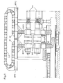
- FIGS. 1 and 2 the two single stands EST1 and EST2, the (Fig. 2) on the left in the drawing, in the closed working position are shown, with the single stand EST2 arranged stationary, as the drive side Stand connected to the drive spindles ASP of the roller drive is.
- the carrier link chain TLK lies on the respective one Support trusses ATR1 and ATR2 on and is attached to this.
- the TLK link plate chain is curved towards above and with a vertical distance above the two support beams ATR1 and ATR2 passed over this.
- the one on the drive side Single stand EST2 opposite single stand EST1 a position P1 in the direction of arrow S1, away from it into position P2 driven and thus created the possibility of the roller set WS on one Carriage FW parallel to the rolling direction in the shown retracted position and from this, transversely to the rolling direction in the direction of arrow S2 onto the single stand EST2 in a manner not shown to move to the installation position. Subsequently can the single stand EST1 back in the same direction Original position P1 pushed back and connected to the roller set.
- the TLK lifting link chain moves unwinding from the starting position AL shown in full lines to the, dash-dotted indicated displacement position VL, and then back out of this the starting position AL. It needs, due to its composition self-supporting straps no external support elements.
- the media feed lines that are routed through and carried by the TLK link plate chain remain with the support beams during these processes ATR1 and ATR2 arranged media connections in a manner not shown coupled connected.
- the carrier chain TLK moves unwinding from the position shown in full lines in the shift position indicated by dash-dotted lines.
- the WS roller set can now move from its lateral position on the FW trolley into the movement path of the single stand EST1 and then, in the direction S2 on the rails FS in front of the single stand EST2 in its not shown Work position. Then the single stand EST1 also moved in the direction S2 to its working position P1.
- the carrier chain TLK moves, rewinding back into that shown in full lines Position.
- the media feed lines remain with the, not shown here, on the single stand EST1 and the intermediate bridge Eg arranged media connections coupled, connected.
Landscapes
- Engineering & Computer Science (AREA)
- Mechanical Engineering (AREA)
- Carriers, Traveling Bodies, And Overhead Traveling Cranes (AREA)
- Bearings For Parts Moving Linearly (AREA)
- Conveying And Assembling Of Building Elements In Situ (AREA)
- Pinball Game Machines (AREA)
- Accommodation For Nursing Or Treatment Tables (AREA)
- Handcart (AREA)
- Metal Rolling (AREA)
- Duct Arrangements (AREA)
Abstract
Description
Die Erfindung betrifft eine Anordnung der über Kuppeleinrichtungen mit Medienanschlüssen der Ständer von Walzgerüsten verbindbaren Medienzuleitungen und Verbindungsleitungen an Walzgerüsten, die Einzelständer aufweisen, von denen der antriebsseitige ortsfest und der andere, von diesem trennbar und in Walzenachsrichtung verfahrbar angeordnet sind.The invention relates to an arrangement of the coupling devices with media connections the stands of roll stands that can be connected to media feed lines and Connection lines on roll stands, which have individual stands, of which the drive-side stationary and the other, separable from it and in the roll axis direction are arranged movable.
Bei Walzgerüsten insb. Mehrwalzgerüsten ist ein Auswechseln der Walzensätze zusammen mit den hier, verhältnismäßig langen Führungsarmaturen nicht oder nur unter großen Schwierigkeiten möglich. Die Walzgerüste bestehen deshalb durchweg aus zwei Einzelständern, die für den Walzenwechsel quer zur Walzrichtung voneinander weg und anschließend wieder aufeinanderzu verfahren werden können.In the case of roll stands, in particular multi-roll stands, the roll sets must be replaced together with the here, relatively long guide fittings or not only possible with great difficulty. The roll stands therefore exist consistently of two single stands, which are used for the roll change across the rolling direction away from each other and then moved towards each other again can.
Vor dem Auseinanderfahren der beiden Einzelständer bzw. des Wegfahrens eines Einzelständers von dem anderen ortsfest angeordneten und mit den Walzenantrieben verbundenen Einzelständer müssen jedoch die zahlreichen, für die Steuerung des Walzgerüstes erforderlichen Medien-Zuleitungen und Verbindungsleitungen für den Betrieb der Hydraulik, der Elektrik, der Schmierung sowie der Wasserund Luftversorgung, die mit entsprechenden Medienanschlüssen an den beiden Einzelständern gekuppelt sind, entkuppelt und nach dem Walzenwechsel für den Walzbetrieb wieder mit diesen Anschlüssen gekuppelt werden. Ein Walzgerüst dieser Ausbildungsform ist in EP 857 522 A1 beschrieben.Before the two individual stands move apart or one moves away Single stand from the other stationary and with the roller drives connected stand, however, the numerous, for control of the roll stand required media supply lines and connecting lines for the operation of hydraulics, electrics, lubrication and water and Air supply with corresponding media connections on the two Individual stands are coupled, uncoupled and after the roll change for the Rolling operation can be coupled again with these connections. A mill stand this form of training is described in EP 857 522 A1.
Neben dem verhältnismäßig großen Bedienungs- und Zeitaufwand, den dieses Entkuppeln und Kuppeln erfordert, besteht für Kupplungen und Leitungen eine große Verschmutzungsgefahr, die z. B. bei den Hydraulikleitungen häufig noch besondere, zeitaufwendige Spülvorgänge erforderlich macht.In addition to the relatively large amount of operation and time that this Uncoupling and coupling required, there is a coupling and cable great risk of pollution, the z. B. often still in the hydraulic lines requires special, time-consuming rinsing processes.
Der Erfindung liegt die Aufgabe zugrunde, die Notwendigkeit des Kuppelns und des Entkuppelns der Medienzuleitungen und den damit verbundenen Bedienungsund Zeitaufwand zu vermeiden.The invention has for its object the need for coupling and the uncoupling of the media supply lines and the associated operating and Avoid spending time.
Diese Aufgabe wird dadurch gelöst, dass die Medienzuleitungen eine, dem Verfahrabstand der beiden Einzelständer entsprechende Länge aufweisen, und während des Verfahrens mit den Medienanschlüssen der Einzelständer gekuppelt verbleibend, in einer selbst-freitragenden Traglaschen-Kette angeordnet sind, deren Enden jeweils mit einem der Einzelständer bzw. mit einer, diesem zugeordneten, seitlich von dessen Bewegungsbahn, diese überbrückend angeordneten Zwischenbrücke verbunden sind.This task is solved in that the media feed lines are one, the travel distance of the two single stands have the appropriate length, and while of the procedure coupled with the media connections of the single stands remaining, are arranged in a self-supporting chain link chain, the Each end with one of the individual stands or with one assigned to it to the side of its trajectory, bridging it Intermediate bridge are connected.
Wie die Erfindung weiter vorsieht, kann dabei die Traglaschen-Kette mit vertikalem Abstand, horizontal oberhalb der beiden Einzelständer über diese hinweggeführt, mit je einem ihrer beiden Enden fest mit einer, auf jedem der Einzelständer angeordneten Auflage-Tragtraverse verbunden und auf diese auflegbar sein.As the invention further provides, the link plate chain can be vertical Distance, horizontally above the two single stands, each with one of its two ends firmly with one, arranged on each of the individual stands Support-support crossbar connected and can be placed on this.
Die Traglaschenkette kann mit einem Ende mit einer, auf dem beweglichen Einzelständer angeordneten Auflagetraverse verbunden, horizontal, mit oder ohne vertikalem Abstand von der Auflagefläche der Auflagetraverse zu der Zwischenbrücke geführt bzw. umgeführt, mit ihrem anderen Ende mit dieser verbunden werden. The carrier chain can have one end with one, on the movable single stand arranged support crossbar connected, horizontally, with or without vertical distance from the support surface of the support crossmember to the intermediate bridge led or redirected, connected at the other end to this become.
Die Traglaschenkette kann auch mit einem Ende mit vertikalem Abstand oberhalb des Anlagenfundaments mit dem beweglichen Einbaustück verbunden und mit diesem Abstand horizontal geführt und nach unten umgeführt, auf dem Anlagenfundament aufliegend mit ihrem Ende auf diesem befestigt werden.The carrier chain can also have one end with a vertical distance above of the system foundation connected to the movable chock and with this distance horizontally and diverted downwards, on the system foundation to be attached to it with its end on it.
Mit der erfindungsgemäßen Ausbildung und Anordnung der Traglaschenkette können die Einzelständer über verhältnismäßig lange Distanzen voneinander weg gefahren und dabei ein Wechsel der Walzensätze ohne Einschränkung bspw. des Kran-Bewegungsbereichs durchgeführt werden. Bei Tandemgerüstanordnungen kann die, die Medienzuleitungen aufnehmende Traglaschenkette ggfs. gestützt durch die Zwischenbrücke frei tragend über eine vollständige Gerüstgruppe z. B. eine Tandemgerüstgruppe ohne Kollision mit deren hier sehr langen Walzgutführungen der Walzensätze hinweggeführt werden.With the inventive design and arrangement of the link plate chain the single stands can move away from each other over relatively long distances driven and thereby a change of the roller sets without restriction, for example Crane range of motion can be performed. With tandem scaffold arrangements can support the carrier chain chain receiving the media feed lines if necessary cantilevered through the intermediate bridge over a complete scaffold group z. B. a tandem stand group without collision with their very long rolling stock guides the roller sets are led away.
Die Erfindung wird anhand der, in der Zeichnung dargestellten Ausführungsbeispiele näher erläutert. In der Zeichnung zeigen
- Fig. 1
- die Ansicht eines Walzgerüstes, in Walzrichtung gesehen,
- Fig. 2
- die Ansicht eines Walzgerüstes nach Fig. 1 in einer Walzanlage und
- Fig. 3
- eine der Ansicht nach Fig. 2 entsprechende Walzanlage anderer Ausbildung.
- Fig. 1
- the view of a roll stand, seen in the rolling direction,
- Fig. 2
- the view of a rolling stand according to FIG. 1 in a rolling mill and
- Fig. 3
- one of the view of FIG. 2 corresponding rolling mill of other training.
Wie aus den Fig. 1 und 2 zu ersehen, weisen die beiden Einzelständer EST1 und EST2, die (Fig. 2) links in der Zeichnung, in zusammengefahrener Arbeitsposition dargestellt sind, wobei der Einzelständer EST2 ortsfest angeordnet, als antriebsseitiger Ständer mit den Antriebsspindeln ASP des Walzenantriebs verbunden ist.As can be seen from FIGS. 1 and 2, the two single stands EST1 and EST2, the (Fig. 2) on the left in the drawing, in the closed working position are shown, with the single stand EST2 arranged stationary, as the drive side Stand connected to the drive spindles ASP of the roller drive is.
Die Traglaschenkette TLK liegt mit ihren beiden Enden E1 bzw. E2 auf dem jeweiligen Auflagetraversen ATR1 bzw. ATR2 auf und ist auf diesem befestigt. Von den beiden Enden E1 und E2 aus ist die Traglaschenkette TLK bogenförmig nach oben und mit vertikalem Abstand oberhalb der beiden Auflagetraversen ATR1 und ATR2 über diese hinweggeführt.With its two ends E1 and E2, the carrier link chain TLK lies on the respective one Support trusses ATR1 and ATR2 on and is attached to this. Of the From both ends E1 and E2, the TLK link plate chain is curved towards above and with a vertical distance above the two support beams ATR1 and ATR2 passed over this.
Für den Einbau des, mit WS bezeichneten Walzensatzes wird der, dem antriebsseitigen Einzelständer EST2 gegenüberliegende Einzelständer EST1 aus einer Position P1 in Richtung des Pfeils S1, von diesem weg in die Position P2 gefahren und damit die Möglichkeit geschaffen, den Walzensatz WS auf einem Fahrwagen FW parallel zur Walzrichtung in die dargestellte Einfahrposition und aus dieser, quer zur Walzrichtung in Richtung des Pfeils S2 auf den Einzelständer EST2 hin auf, nicht dargestellte Weise, in die Einbauposition zu verschieben. Anschließend kann der Einzelständer EST1 in der gleichen Richtung wieder in die Ursprungsposition P1 zurückgeschoben und mit dem Walzensatz verbunden werden.For the installation of the roller set designated WS, the one on the drive side Single stand EST2 opposite single stand EST1 a position P1 in the direction of arrow S1, away from it into position P2 driven and thus created the possibility of the roller set WS on one Carriage FW parallel to the rolling direction in the shown retracted position and from this, transversely to the rolling direction in the direction of arrow S2 onto the single stand EST2 in a manner not shown to move to the installation position. Subsequently can the single stand EST1 back in the same direction Original position P1 pushed back and connected to the roller set.
Bei diesen Verschiebevorgängen bewegt sich die Traglaschenkette TLK abwikkelnd aus der, in vollen Linien wiedergegebenen Ausgangslage AL in die, strichpunktiert angedeutete Verschiebelage VL, und dann aus dieser wieder zurück in die Ausgangslage AL. Sie bedarf dabei, infolge ihrer Zusammensetzung aus selbst-freitragenden Traglaschen keiner äußeren Stützelemente.During these shifting processes, the TLK lifting link chain moves unwinding from the starting position AL shown in full lines to the, dash-dotted indicated displacement position VL, and then back out of this the starting position AL. It needs, due to its composition self-supporting straps no external support elements.
Die durch die Traglaschenkette TLK geführten und von dieser getragenen Medienzuleitungen bleiben während dieser Vorgänge mit, auf den Auflagetraversen ATR1 und ATR2 auf nicht dargestellte Weise angeordneten Medienanschlüssen gekuppelt verbunden.The media feed lines that are routed through and carried by the TLK link plate chain remain with the support beams during these processes ATR1 and ATR2 arranged media connections in a manner not shown coupled connected.
Bei der in Fig. 3 wiedergegebenen Anordnung ist, quer zur Walzrichtung, in einem Abstand d vor dem verfahrbaren Einzelständer EST1 seitlich von dessen Bewegungsbahn eine Zwischenbrücke ZB mit einer Galerie GL angeordnet, die die Bewegungsbahn überbrückt. Die, mit einem Ende E1 auf der Auflagetraverse ATR1 des verfahrbaren Einzelständers EST1 aufliegende, in vollen Linien dargestellte Traglaschenkette TLK ist in Verfahrrichtung S1 des Einzelständers EST1 in einer horizontalen Ebene ausgerollt und mit ihrem freien Ende E2 an einem Kragausleger KA der Galerie GL der Zwischenbrücke ZB befestigt. Wenn der Einzelständer EST1 in der Richtung S1 von dem Einzelständer EST2 weg in die Position P3 gefahren wird, befindet sich der Walzensatz WS auf dem Fahrwagen FW aufstehend, außerhalb der Bewegungsbahn des Einzelständers EST1. Die Traglaschenkette TLK bewegt sich dabei aus der, in vollen Linien wiedergegebenen Lage abwickelnd in die strichpunktiert angedeutete Verschiebelage. Der Walzensatz WS kann nun aus seiner seitlichen Position heraus auf dem Fahrwagen FW in die Bewegungsbahn des Einzelständers EST1 verschoben und dann, in der Richtung S2 auf den Fahrschienen FS vor den Einzelständer EST2 in seine nicht dargestellte Arbeitsstellung gebracht werden. Anschließend wird der Einzelständer EST1 ebenfalls in der Richtung S2 in seine Arbeitsposition P1 gefahren. Die Traglaschenkette TLK bewegt sich dabei, rückwickelnd wieder in die in vollen Linien dargestellte Position.In the arrangement shown in FIG. 3, in one direction, transverse to the rolling direction Distance d in front of the movable single stand EST1 to the side of its movement path an intermediate bridge ZB with a gallery GL arranged the movement path bridged. The one end E1 on the support crossbar ATR1 of the movable single stand EST1, shown in full lines Carrier link chain TLK is in one in the travel direction S1 of the single stand EST1 horizontal plane rolled out and with its free end E2 on a cantilever KA of the gallery GL of the intermediate bridge ZB attached. If the single stand EST1 in direction S1 moved away from the single stand EST2 into position P3 the roller set WS is standing up on the carriage FW, outside the movement path of the single stand EST1. The carrier chain TLK moves unwinding from the position shown in full lines in the shift position indicated by dash-dotted lines. The WS roller set can now move from its lateral position on the FW trolley into the movement path of the single stand EST1 and then, in the direction S2 on the rails FS in front of the single stand EST2 in its not shown Work position. Then the single stand EST1 also moved in the direction S2 to its working position P1. The carrier chain TLK moves, rewinding back into that shown in full lines Position.
Auch hier bleiben, wie bei der Ausbildung nach Fig. 1 und 2 die Medienzuleitungen mit den, hier nicht dargestellten, auf dem Einzelständer EST1 und der Zwischenbrücke ZB angeordneten Medienanschlüssen gekuppelt, verbunden. Here too, as in the embodiment according to FIGS. 1 and 2, the media feed lines remain with the, not shown here, on the single stand EST1 and the intermediate bridge Eg arranged media connections coupled, connected.
- EST1EST1
- EinzelständerSingle stand
- EST2EST2
- EinzelständerSingle stand
- ASPASP
- Antriebsspindeldrive spindle
- ATR1ATR1
- Auflagetraverseedition Traverse
- ATR2ATR2
- Auflagetraverseedition Traverse
- TLKTLK
- TraglaschenketteSupporting plate chain
- E1E1
- Ende der TLKEnd of the TLK
- E2E2
- Ende der TLKEnd of the TLK
- WSWS
- Walzensatzroll set
- P1P1
- Positionposition
- P2P2
- Positionposition
- P3P3
- Positionposition
- FWFW
- Fahrwagentrolley
- ALAL
- Ausgangslagestarting position
- VLVL
- Verschiebelagedisplacement position
- ZBFor example,
- Zwischenbrückebetween bridge
- KAKA
- KragauslegerKragausleger
- GLGL
- Galeriegallery
- FSFS
- Fahrschienerunning rail
- dd
- Abstanddistance
- S1S1
- Fahrrichtungdriving direction
- S2S2
- Fahrrichtungdriving direction
Claims (6)
dadurch gekennzeichnet,. dass die Medienzuleitungen eine, dem Verfahrabstand der beiden Einzelständer (EST1; EST2) entsprechende Länge aufweisen und während des Verfahrens mit den Medienanschlüssen der Einzelständer (EST1; EST2) gekuppelt verbleibend, in einer selbst-freitragenden Traglaschenkette (TLK) angeordnet sind, deren Enden (E1; E2) jeweils mit einem der Einzelständer (EST1; EST2) bzw. mit einer, diesem zugeordneten, seitlich von dessen Bewegungsbahn, diese überbrückend angeordneten Zwischenbrücke (ZB) verbunden sind.Arrangement of the media feed lines and connecting lines on the rolling stands, which can be connected via coupling devices with media connections of the stands of rolling stands, which have single stands (EST1; EST2), of which the drive-side single stand (EST2) is stationary and the other single stand (EST1), separable from it and in the direction of the roll axis (S1; S2) are arranged to be movable
characterized,. that the media feed lines have a length corresponding to the travel distance of the two single stands (EST1; EST2) and remain coupled during the procedure with the media connections of the single stands (EST1; EST2), are arranged in a self-supporting chain link chain (TLK), the ends ( E1; E2) are each connected to one of the individual stands (EST1; EST2) or to an intermediate bridge (ZB), which is arranged to bridge this and laterally from its path of movement.
dadurch gekennzeichnet, dass die Traglaschenkette (TLK) mit vertikalem Abstand (h) horizontal oberhalb der beiden Einzelständer (EST1; EST2) über diese hinwegführt, mit ihren beiden Enden (E1, E2) fest mit, auf jeden der Einzelständer (EST1; EST2) angeordneten Auflagetraversen (ATR1; ATR2) verbunden und auf diese auflegbar ist. Arrangement according to claim 1,
characterized in that the carrier link chain (TLK) with vertical distance (h) horizontally above the two single stands (EST1; EST2) passes over them, with both ends (E1, E2) firmly on each of the single stands (EST1; EST2) arranged support beams (ATR1; ATR2) connected and can be placed on them.
dadurch gekennzeichnet, dass die Traglaschenkette mit einem Ende mit einer, auf dem beweglichen Einzelständer angeordneten Auflagetraverse verbunden, horizontal, mit oder ohne vertikalem Abstand von der Auflagefläche der Auflagetraverse zu der Zwischenbrücke geführt bzw. umgeführt, mit ihrem anderen Ende mit dieser verbunden ist.Arrangement according to claim 1,
characterized in that the link plate chain is connected at one end to a support crossbeam arranged on the movable single stand, is guided horizontally, with or without a vertical distance from the support surface of the support crossbeam to the intermediate bridge, and is connected at its other end to the latter.
dadurch gekennzeichnet, dass die Traglaschenkette mit einem Ende, mit vertikalem Abstand oberhalb des Anlagenfundaments mit dem beweglichen Einzelständer verbunden und mit diesem Abstand, horizontal geführt und nach unten umgeführt auf dem Anlagenflur aufliegend, mit ihrem Ende auf diesem befestigt ist.Arrangement according to claim 1,
characterized in that the link plate chain is connected at one end, at a vertical distance above the system foundation, to the movable single stand, and with this distance, guided horizontally and lying down on the system corridor, is fastened with its end to it.
dadurch gekennzeichnet, dass die Medienzuleitungen in den Traglaschenketten mit Medienanschlüssen kuppelbar sind, die über ortsfest angeordnete Zwischenleitungen zu der Zwischenbrücke rücken bzw. im ortsfesten Einzelständer geführt sind.Arrangement according to one or more of claims 1 to 4,
characterized in that the media feed lines in the carrier link chains can be coupled to media connections which move to the intermediate bridge via fixedly arranged intermediate lines or are guided in the stationary single stand.
dadurch gekennzeichnet, dass die Zwischenbrücke als Hängebrücke über dem Anlagenfundament ausgebildet ist.Arrangement according to one of Claims 1, 3 and 5,
characterized in that the intermediate bridge is designed as a suspension bridge over the system foundation.
Applications Claiming Priority (2)
| Application Number | Priority Date | Filing Date | Title |
|---|---|---|---|
| DE10108418 | 2001-02-21 | ||
| DE10108418A DE10108418A1 (en) | 2001-02-21 | 2001-02-21 | Arrangement of the media supply lines and connecting lines that can be connected via coupling devices with media connections of the stands of rolling stands |
Publications (3)
| Publication Number | Publication Date |
|---|---|
| EP1234620A2 true EP1234620A2 (en) | 2002-08-28 |
| EP1234620A3 EP1234620A3 (en) | 2005-02-09 |
| EP1234620B1 EP1234620B1 (en) | 2007-02-28 |
Family
ID=7675035
Family Applications (1)
| Application Number | Title | Priority Date | Filing Date |
|---|---|---|---|
| EP02001627A Expired - Lifetime EP1234620B1 (en) | 2001-02-21 | 2002-01-24 | Arrangement of the connecting and medium supply lines which are connectible to the housings of rolling mill stands through coupling devices |
Country Status (4)
| Country | Link |
|---|---|
| EP (1) | EP1234620B1 (en) |
| AT (1) | ATE355139T1 (en) |
| DE (2) | DE10108418A1 (en) |
| ES (1) | ES2282332T3 (en) |
Families Citing this family (1)
| Publication number | Priority date | Publication date | Assignee | Title |
|---|---|---|---|---|
| DE102018219874B4 (en) * | 2018-11-20 | 2020-08-20 | Sms Group Gmbh | Quick-change roll stand |
Citations (4)
| Publication number | Priority date | Publication date | Assignee | Title |
|---|---|---|---|---|
| JPS5779009A (en) * | 1980-10-31 | 1982-05-18 | Nippon Kokan Kk <Nkk> | Rearranging device for rolling stand |
| EP0857522A1 (en) * | 1997-01-16 | 1998-08-12 | Sms Schloemann-Siemag Aktiengesellschaft | Rolling mill |
| JPH10286611A (en) * | 1997-04-15 | 1998-10-27 | Sumitomo Heavy Ind Ltd | Device for changing mill housing |
| EP1232807A2 (en) * | 2001-01-27 | 2002-08-21 | SMS Demag AG | Rolling-mill train with sequential stands, in particular a tandem rolling installation |
-
2001
- 2001-02-21 DE DE10108418A patent/DE10108418A1/en not_active Withdrawn
-
2002
- 2002-01-24 ES ES02001627T patent/ES2282332T3/en not_active Expired - Lifetime
- 2002-01-24 AT AT02001627T patent/ATE355139T1/en active
- 2002-01-24 EP EP02001627A patent/EP1234620B1/en not_active Expired - Lifetime
- 2002-01-24 DE DE50209563T patent/DE50209563D1/en not_active Expired - Lifetime
Patent Citations (4)
| Publication number | Priority date | Publication date | Assignee | Title |
|---|---|---|---|---|
| JPS5779009A (en) * | 1980-10-31 | 1982-05-18 | Nippon Kokan Kk <Nkk> | Rearranging device for rolling stand |
| EP0857522A1 (en) * | 1997-01-16 | 1998-08-12 | Sms Schloemann-Siemag Aktiengesellschaft | Rolling mill |
| JPH10286611A (en) * | 1997-04-15 | 1998-10-27 | Sumitomo Heavy Ind Ltd | Device for changing mill housing |
| EP1232807A2 (en) * | 2001-01-27 | 2002-08-21 | SMS Demag AG | Rolling-mill train with sequential stands, in particular a tandem rolling installation |
Non-Patent Citations (2)
| Title |
|---|
| PATENT ABSTRACTS OF JAPAN Bd. 0061, Nr. 63 (M-152), 26. August 1982 (1982-08-26) -& JP 57 079009 A (NIPPON KOKAN KK <NKK>), 18. Mai 1982 (1982-05-18) * |
| PATENT ABSTRACTS OF JAPAN Bd. 1999, Nr. 01, 29. Januar 1999 (1999-01-29) -& JP 10 286611 A (SUMITOMO HEAVY IND LTD), 27. Oktober 1998 (1998-10-27) * |
Also Published As
| Publication number | Publication date |
|---|---|
| EP1234620A3 (en) | 2005-02-09 |
| DE50209563D1 (en) | 2007-04-12 |
| DE10108418A1 (en) | 2002-08-29 |
| EP1234620B1 (en) | 2007-02-28 |
| ES2282332T3 (en) | 2007-10-16 |
| ATE355139T1 (en) | 2006-03-15 |
Similar Documents
| Publication | Publication Date | Title |
|---|---|---|
| DE69510136T2 (en) | Modular rolling mill | |
| AT392305B (en) | DEVICE FOR REPLACING ELASTIC ROLLING OF A SUPER CALENDAR | |
| EP0593002B1 (en) | Method and device for rolling of hot wide strip of continuously cast thin stabs | |
| DE2912783C2 (en) | Device for synchronously guiding the load suspension gear of a circular chain conveyor provided with suspension links and a truck of a drag chain conveyor | |
| DE3529364C2 (en) | ||
| EP0857522B1 (en) | Rolling mill | |
| DE19520234C1 (en) | Arrangement for die pressing of ceramic articles, esp. bathroom fittings | |
| EP0857152B1 (en) | Method and device for extracting rolling pallets in compact storage technology, and rolling pallet therefor | |
| EP1572386B1 (en) | Rolling mill comprising means for the change of rolls | |
| DE1652550C3 (en) | Plant for rolling mills for changing rolls | |
| EP0329998B1 (en) | Rolling train, especially one in a section-rolling mill | |
| EP1234620B1 (en) | Arrangement of the connecting and medium supply lines which are connectible to the housings of rolling mill stands through coupling devices | |
| EP0857521A1 (en) | Rolling mill | |
| WO2019224060A1 (en) | Straightening machine | |
| EP0432532B2 (en) | High performance bar or wire rolling mill | |
| AT402630B (en) | DETACHABLE ROPE CLAMP DETACHABLE ROPE CLAMP | |
| DE2618747A1 (en) | PROCESS FOR REPLACING SUPPORT ROLLERS OR DRIVE ROLLERS IN A CONTINUOUS CASTING PLANT AND EQUIPMENT FOR PERFORMING THE PROCESS | |
| DE4423930C2 (en) | Device for maintaining a mill | |
| DE2721436A1 (en) | Draw chain mounted on roll changing wagon - for rapid replacement of worn rolls in rolling mills | |
| DE3902889C2 (en) | Open rolling mill with roll stands arranged side by side | |
| EP0073848B1 (en) | Roller arrangement for a rope-driven single-rail suspension railway | |
| DE3237904A1 (en) | Device for the exchange of rolls in a tube rolling mill | |
| DE3000103C2 (en) | Device for guiding a traction mechanism with several pulleys leading the respective traction mechanism strand and / or empty strand | |
| DE102020204652A1 (en) | System for changing a segment in a continuous caster | |
| DE10250431A1 (en) | Rolling mill with support plates |
Legal Events
| Date | Code | Title | Description |
|---|---|---|---|
| PUAI | Public reference made under article 153(3) epc to a published international application that has entered the european phase |
Free format text: ORIGINAL CODE: 0009012 |
|
| AK | Designated contracting states |
Kind code of ref document: A2 Designated state(s): AT BE CH CY DE DK ES FI FR GB GR IE IT LI LU MC NL PT SE TR |
|
| AX | Request for extension of the european patent |
Free format text: AL;LT;LV;MK;RO;SI |
|
| PUAL | Search report despatched |
Free format text: ORIGINAL CODE: 0009013 |
|
| AK | Designated contracting states |
Kind code of ref document: A3 Designated state(s): AT BE CH CY DE DK ES FI FR GB GR IE IT LI LU MC NL PT SE TR |
|
| AX | Request for extension of the european patent |
Extension state: AL LT LV MK RO SI |
|
| 17P | Request for examination filed |
Effective date: 20050707 |
|
| AKX | Designation fees paid |
Designated state(s): AT BE CH CY DE DK ES FI FR GB GR IE IT LI LU MC NL PT SE TR |
|
| GRAP | Despatch of communication of intention to grant a patent |
Free format text: ORIGINAL CODE: EPIDOSNIGR1 |
|
| GRAS | Grant fee paid |
Free format text: ORIGINAL CODE: EPIDOSNIGR3 |
|
| GRAA | (expected) grant |
Free format text: ORIGINAL CODE: 0009210 |
|
| AK | Designated contracting states |
Kind code of ref document: B1 Designated state(s): AT BE CH CY DE DK ES FI FR GB GR IE IT LI LU MC NL PT SE TR |
|
| PG25 | Lapsed in a contracting state [announced via postgrant information from national office to epo] |
Ref country code: NL Free format text: LAPSE BECAUSE OF FAILURE TO SUBMIT A TRANSLATION OF THE DESCRIPTION OR TO PAY THE FEE WITHIN THE PRESCRIBED TIME-LIMIT Effective date: 20070228 Ref country code: FI Free format text: LAPSE BECAUSE OF FAILURE TO SUBMIT A TRANSLATION OF THE DESCRIPTION OR TO PAY THE FEE WITHIN THE PRESCRIBED TIME-LIMIT Effective date: 20070228 Ref country code: DK Free format text: LAPSE BECAUSE OF FAILURE TO SUBMIT A TRANSLATION OF THE DESCRIPTION OR TO PAY THE FEE WITHIN THE PRESCRIBED TIME-LIMIT Effective date: 20070228 |
|
| REG | Reference to a national code |
Ref country code: GB Ref legal event code: FG4D Free format text: NOT ENGLISH |
|
| REG | Reference to a national code |
Ref country code: CH Ref legal event code: EP |
|
| REF | Corresponds to: |
Ref document number: 50209563 Country of ref document: DE Date of ref document: 20070412 Kind code of ref document: P |
|
| REG | Reference to a national code |
Ref country code: IE Ref legal event code: FG4D Free format text: LANGUAGE OF EP DOCUMENT: GERMAN |
|
| PG25 | Lapsed in a contracting state [announced via postgrant information from national office to epo] |
Ref country code: SE Free format text: LAPSE BECAUSE OF FAILURE TO SUBMIT A TRANSLATION OF THE DESCRIPTION OR TO PAY THE FEE WITHIN THE PRESCRIBED TIME-LIMIT Effective date: 20070531 |
|
| GBT | Gb: translation of ep patent filed (gb section 77(6)(a)/1977) |
Effective date: 20070606 |
|
| PG25 | Lapsed in a contracting state [announced via postgrant information from national office to epo] |
Ref country code: PT Free format text: LAPSE BECAUSE OF FAILURE TO SUBMIT A TRANSLATION OF THE DESCRIPTION OR TO PAY THE FEE WITHIN THE PRESCRIBED TIME-LIMIT Effective date: 20070730 |
|
| NLV1 | Nl: lapsed or annulled due to failure to fulfill the requirements of art. 29p and 29m of the patents act | ||
| REG | Reference to a national code |
Ref country code: ES Ref legal event code: FG2A Ref document number: 2282332 Country of ref document: ES Kind code of ref document: T3 |
|
| EN | Fr: translation not filed | ||
| REG | Reference to a national code |
Ref country code: IE Ref legal event code: FD4D |
|
| PLBE | No opposition filed within time limit |
Free format text: ORIGINAL CODE: 0009261 |
|
| STAA | Information on the status of an ep patent application or granted ep patent |
Free format text: STATUS: NO OPPOSITION FILED WITHIN TIME LIMIT |
|
| PG25 | Lapsed in a contracting state [announced via postgrant information from national office to epo] |
Ref country code: IE Free format text: LAPSE BECAUSE OF FAILURE TO SUBMIT A TRANSLATION OF THE DESCRIPTION OR TO PAY THE FEE WITHIN THE PRESCRIBED TIME-LIMIT Effective date: 20070228 |
|
| 26N | No opposition filed |
Effective date: 20071129 |
|
| PG25 | Lapsed in a contracting state [announced via postgrant information from national office to epo] |
Ref country code: FR Free format text: LAPSE BECAUSE OF FAILURE TO SUBMIT A TRANSLATION OF THE DESCRIPTION OR TO PAY THE FEE WITHIN THE PRESCRIBED TIME-LIMIT Effective date: 20071019 Ref country code: GR Free format text: LAPSE BECAUSE OF FAILURE TO SUBMIT A TRANSLATION OF THE DESCRIPTION OR TO PAY THE FEE WITHIN THE PRESCRIBED TIME-LIMIT Effective date: 20070529 |
|
| BERE | Be: lapsed |
Owner name: MS DEMAG AG Effective date: 20080131 |
|
| PG25 | Lapsed in a contracting state [announced via postgrant information from national office to epo] |
Ref country code: MC Free format text: LAPSE BECAUSE OF NON-PAYMENT OF DUE FEES Effective date: 20080131 |
|
| REG | Reference to a national code |
Ref country code: CH Ref legal event code: PL |
|
| PG25 | Lapsed in a contracting state [announced via postgrant information from national office to epo] |
Ref country code: CH Free format text: LAPSE BECAUSE OF NON-PAYMENT OF DUE FEES Effective date: 20080131 Ref country code: LI Free format text: LAPSE BECAUSE OF NON-PAYMENT OF DUE FEES Effective date: 20080131 |
|
| PG25 | Lapsed in a contracting state [announced via postgrant information from national office to epo] |
Ref country code: FR Free format text: LAPSE BECAUSE OF FAILURE TO SUBMIT A TRANSLATION OF THE DESCRIPTION OR TO PAY THE FEE WITHIN THE PRESCRIBED TIME-LIMIT Effective date: 20070228 |
|
| PG25 | Lapsed in a contracting state [announced via postgrant information from national office to epo] |
Ref country code: BE Free format text: LAPSE BECAUSE OF NON-PAYMENT OF DUE FEES Effective date: 20080131 |
|
| PG25 | Lapsed in a contracting state [announced via postgrant information from national office to epo] |
Ref country code: CY Free format text: LAPSE BECAUSE OF FAILURE TO SUBMIT A TRANSLATION OF THE DESCRIPTION OR TO PAY THE FEE WITHIN THE PRESCRIBED TIME-LIMIT Effective date: 20070228 |
|
| PG25 | Lapsed in a contracting state [announced via postgrant information from national office to epo] |
Ref country code: LU Free format text: LAPSE BECAUSE OF NON-PAYMENT OF DUE FEES Effective date: 20080124 |
|
| PG25 | Lapsed in a contracting state [announced via postgrant information from national office to epo] |
Ref country code: TR Free format text: LAPSE BECAUSE OF FAILURE TO SUBMIT A TRANSLATION OF THE DESCRIPTION OR TO PAY THE FEE WITHIN THE PRESCRIBED TIME-LIMIT Effective date: 20070228 |
|
| PGFP | Annual fee paid to national office [announced via postgrant information from national office to epo] |
Ref country code: DE Payment date: 20130122 Year of fee payment: 12 |
|
| REG | Reference to a national code |
Ref country code: DE Ref legal event code: R042 Ref document number: 50209563 Country of ref document: DE Effective date: 20130523 |
|
| PG25 | Lapsed in a contracting state [announced via postgrant information from national office to epo] |
Ref country code: DE Free format text: THE PATENT HAS BEEN ANNULLED BY A DECISION OF A NATIONAL AUTHORITY Effective date: 20130523 |
|
| PGFP | Annual fee paid to national office [announced via postgrant information from national office to epo] |
Ref country code: AT Payment date: 20210121 Year of fee payment: 20 Ref country code: ES Payment date: 20210324 Year of fee payment: 20 Ref country code: GB Payment date: 20210121 Year of fee payment: 20 |
|
| PGFP | Annual fee paid to national office [announced via postgrant information from national office to epo] |
Ref country code: IT Payment date: 20210121 Year of fee payment: 20 |
|
| REG | Reference to a national code |
Ref country code: GB Ref legal event code: PE20 Expiry date: 20220123 |
|
| REG | Reference to a national code |
Ref country code: AT Ref legal event code: MK07 Ref document number: 355139 Country of ref document: AT Kind code of ref document: T Effective date: 20220124 |
|
| PG25 | Lapsed in a contracting state [announced via postgrant information from national office to epo] |
Ref country code: GB Free format text: LAPSE BECAUSE OF EXPIRATION OF PROTECTION Effective date: 20220123 |
|
| REG | Reference to a national code |
Ref country code: ES Ref legal event code: FD2A Effective date: 20220429 |
|
| PG25 | Lapsed in a contracting state [announced via postgrant information from national office to epo] |
Ref country code: ES Free format text: LAPSE BECAUSE OF EXPIRATION OF PROTECTION Effective date: 20220125 |