EP1233713B1 - Implantat für osteosynthesen - Google Patents
Implantat für osteosynthesen Download PDFInfo
- Publication number
- EP1233713B1 EP1233713B1 EP00972856A EP00972856A EP1233713B1 EP 1233713 B1 EP1233713 B1 EP 1233713B1 EP 00972856 A EP00972856 A EP 00972856A EP 00972856 A EP00972856 A EP 00972856A EP 1233713 B1 EP1233713 B1 EP 1233713B1
- Authority
- EP
- European Patent Office
- Prior art keywords
- plate
- holes
- implant according
- screw
- bone
- Prior art date
- Legal status (The legal status is an assumption and is not a legal conclusion. Google has not performed a legal analysis and makes no representation as to the accuracy of the status listed.)
- Expired - Lifetime
Links
- 239000007943 implant Substances 0.000 title claims abstract description 29
- 230000001154 acute effect Effects 0.000 claims abstract description 8
- 210000000988 bone and bone Anatomy 0.000 claims description 60
- 230000007704 transition Effects 0.000 claims description 5
- 229920001169 thermoplastic Polymers 0.000 claims description 4
- 239000004416 thermosoftening plastic Substances 0.000 claims description 4
- 208000010392 Bone Fractures Diseases 0.000 description 8
- 208000037265 diseases, disorders, signs and symptoms Diseases 0.000 description 6
- 208000035475 disorder Diseases 0.000 description 6
- 238000004519 manufacturing process Methods 0.000 description 6
- 239000012634 fragment Substances 0.000 description 5
- 238000005452 bending Methods 0.000 description 4
- 230000005540 biological transmission Effects 0.000 description 4
- 208000006735 Periostitis Diseases 0.000 description 3
- 238000001125 extrusion Methods 0.000 description 3
- 230000035876 healing Effects 0.000 description 3
- 238000000034 method Methods 0.000 description 3
- 210000003460 periosteum Anatomy 0.000 description 3
- 238000003825 pressing Methods 0.000 description 3
- 206010020649 Hyperkeratosis Diseases 0.000 description 2
- 210000004204 blood vessel Anatomy 0.000 description 2
- 238000010276 construction Methods 0.000 description 2
- 238000013461 design Methods 0.000 description 2
- 238000011156 evaluation Methods 0.000 description 2
- 230000002441 reversible effect Effects 0.000 description 2
- 230000006641 stabilisation Effects 0.000 description 2
- 238000011105 stabilization Methods 0.000 description 2
- 210000002435 tendon Anatomy 0.000 description 2
- 210000001519 tissue Anatomy 0.000 description 2
- 238000012546 transfer Methods 0.000 description 2
- 208000006386 Bone Resorption Diseases 0.000 description 1
- 208000004221 Multiple Trauma Diseases 0.000 description 1
- 208000001132 Osteoporosis Diseases 0.000 description 1
- 206010052428 Wound Diseases 0.000 description 1
- 208000027418 Wounds and injury Diseases 0.000 description 1
- 230000006978 adaptation Effects 0.000 description 1
- 238000013459 approach Methods 0.000 description 1
- 230000009286 beneficial effect Effects 0.000 description 1
- 230000033228 biological regulation Effects 0.000 description 1
- 230000015572 biosynthetic process Effects 0.000 description 1
- 230000024279 bone resorption Effects 0.000 description 1
- 238000003776 cleavage reaction Methods 0.000 description 1
- 230000007850 degeneration Effects 0.000 description 1
- 230000002349 favourable effect Effects 0.000 description 1
- 239000000835 fiber Substances 0.000 description 1
- 210000000245 forearm Anatomy 0.000 description 1
- 238000003780 insertion Methods 0.000 description 1
- 230000037431 insertion Effects 0.000 description 1
- 210000001699 lower leg Anatomy 0.000 description 1
- 239000000463 material Substances 0.000 description 1
- 210000003739 neck Anatomy 0.000 description 1
- 230000017074 necrotic cell death Effects 0.000 description 1
- 239000011505 plaster Substances 0.000 description 1
- 230000036316 preload Effects 0.000 description 1
- 230000003252 repetitive effect Effects 0.000 description 1
- 230000007017 scission Effects 0.000 description 1
- 238000007493 shaping process Methods 0.000 description 1
- 210000004872 soft tissue Anatomy 0.000 description 1
- 210000002303 tibia Anatomy 0.000 description 1
- 230000000451 tissue damage Effects 0.000 description 1
- 231100000827 tissue damage Toxicity 0.000 description 1
- 230000003313 weakening effect Effects 0.000 description 1
Images
Classifications
-
- A—HUMAN NECESSITIES
- A61—MEDICAL OR VETERINARY SCIENCE; HYGIENE
- A61B—DIAGNOSIS; SURGERY; IDENTIFICATION
- A61B17/00—Surgical instruments, devices or methods
- A61B17/56—Surgical instruments or methods for treatment of bones or joints; Devices specially adapted therefor
- A61B17/58—Surgical instruments or methods for treatment of bones or joints; Devices specially adapted therefor for osteosynthesis, e.g. bone plates, screws or setting implements
- A61B17/68—Internal fixation devices, including fasteners and spinal fixators, even if a part thereof projects from the skin
- A61B17/80—Cortical plates, i.e. bone plates; Instruments for holding or positioning cortical plates, or for compressing bones attached to cortical plates
- A61B17/8052—Cortical plates, i.e. bone plates; Instruments for holding or positioning cortical plates, or for compressing bones attached to cortical plates immobilised relative to screws by interlocking form of the heads and plate holes, e.g. conical or threaded
- A61B17/8057—Cortical plates, i.e. bone plates; Instruments for holding or positioning cortical plates, or for compressing bones attached to cortical plates immobilised relative to screws by interlocking form of the heads and plate holes, e.g. conical or threaded the interlocking form comprising a thread
-
- A—HUMAN NECESSITIES
- A61—MEDICAL OR VETERINARY SCIENCE; HYGIENE
- A61B—DIAGNOSIS; SURGERY; IDENTIFICATION
- A61B17/00—Surgical instruments, devices or methods
- A61B17/56—Surgical instruments or methods for treatment of bones or joints; Devices specially adapted therefor
- A61B17/58—Surgical instruments or methods for treatment of bones or joints; Devices specially adapted therefor for osteosynthesis, e.g. bone plates, screws or setting implements
- A61B17/68—Internal fixation devices, including fasteners and spinal fixators, even if a part thereof projects from the skin
- A61B17/84—Fasteners therefor or fasteners being internal fixation devices
- A61B17/86—Pins or screws or threaded wires; nuts therefor
- A61B17/8605—Heads, i.e. proximal ends projecting from bone
- A61B17/861—Heads, i.e. proximal ends projecting from bone specially shaped for gripping driver
Definitions
- the invention relates to an implant for osteosynthesis, consisting of one with several in Longitudinally successive holes provided plate and through the holes in the Insert plate through and screwed in the intended position in a bone Screws, wherein at least one size of the part intended to accommodate the screws Holes offset in relation to an imaginary center plane of the plate alternately outwards are, wherein the central axes of the holes with the imaginary center plane of the plate a Include acute angle and the holes of the intended outside Rejuvenate the surface of the plate.
- a known bone plate (DE 86 28 766 U) offset laterally to the central longitudinal axis
- the plate is to adapt to the bone surface curved about an axis parallel to the longitudinal axis or in any other way (in particular by polygonal cross-section) of a cylindrical shape approximated.
- the width of the Plate corresponds throughout in about the width of a normal narrow plate, wherein the course of this plate through the recesses a zigzag character receives.
- the plate can also get a helical twist, so that ever according to the type of fracture the optimal attachment points can be achieved in this case.
- the plates consistently relatively wide and thus difficult by deformation are adapted to the particular fracture situations, the purpose is the well-known bone plate be formed so that they by an individual shaping to a larger number of Fracture types is customizable.
- a bone plate has become known (EP 0 206 767 A), in which the holes laterally are offset to the central longitudinal axis, the holes counterbores substantially in the form of a section of a sphere and the underside of the head the screws have a corresponding cross-sectional shape. This allows the screw head always lie snugly in the countersink of the bone plate. An angular stable position between bone plate and screw can not be achieved here.
- the present invention has for its object to provide an implant of the aforementioned To create a kind, with which the power transmission over a plate both from mechanical as well as biological view can be significantly improved.
- the holes of the plate taper conically. that the screws correspond to one of the sections formed by the holes, tapering to your threaded shaft tapering head have, which is positively and / or positively fixed in the holes, that the plate in The longitudinal direction seen running multiply wound, being in the range of the individual Holes the main orientation transverse to the longitudinal extent of the plate at right angles to the central axis of the corresponding hole, and that the plate from the side her seen slightly bent, with a laid by the ends of the plate Tendon has distance from a middle section of the plate.
- the holes in the bones for the use of screws are not in a row aligned.
- the fragment cleavage is thereby substantially prevented and also This results in significantly less circulatory disorders.
- This affects the convergence of the screws used.
- the successive Screws inserted on a bone thus intersect approximately in the center of the medullary cavity in the bone.
- the torsional stability of Plattenösteosynthese significantly increased.
- Implanted in a line relatively close to each other Screws can cause splitting of the bone when subjected to strong torsional forces.
- Screws implanted in a line relatively close to one another can also be passed through Interruption of the blood vessels running in the longitudinal Haverian channels rather cause an unfavorable circulatory disorder than each other offset holes and thus as successive crossing screws.
- the inventive measures a step is achieved in an elastic plate , whereby by the movement possibilities a natural bone healing with callus formation is expected, as earlier just in the application of a plaster of Case was.
- the plate is wound several times in its longitudinal direction is executed, wherein in the region of the individual holes, the main orientation transversely to the longitudinal extent of the plate at right angles to the central axis of the corresponding Hole runs, the plate is in the respective mounting area approximately parallel to Surface of the bone. It is thus essentially always a constant gap given between bone and plate.
- the side boundaries of the plate substantially the offset holes and follow the outer contours of the holes, so that the plate over their Length seen in plan view has a substantially wave-shaped course. Thereby is about the length of the plate at least approximately a constant stability despite a material-saving production became possible. It is therefore also guaranteed that the plate to be used is not oversized.
- the imaginary center plane of the plate also the median plane of the middle section of the plate is. This facilitates the centering of the Plate on the bone.
- cams form "feet" on the plate edges, which are mainly beneficial in panel mounting could be.
- These cams prevent a full-surface concern of the plate on the bone, can optionally increase the torsional stability or the screw necks on Relieve transition between screw shaft and head.
- the cams alone is the Circulation of the bone is not significantly disturbed. Due to the stoppage of the screws in the plate itself is achieved that the plate finally a certain distance from the surface of the bone
- the two ends and edges and transitions of the plate are made flat and rounded.
- Another special embodiment provides that the central axes of the holes with the imaginary Center plane of the plate at an acute angle of 15 °.
- the acute-angled Turning the screws and the intersecting holes with screws will be the Torsion stability of the osteosynthesis significantly improved.
- the screws are essential Less stressed to bending.
- the invention proposes that the plate made of fiber-reinforced thermoplastics is made and the anisotropy of the elastic properties of the plate on the Elasticity or rigidity of the bone is set.
- the osteosynthesis plate system according to the invention is thus designed as an elastic fixation. It is thus a homoelasticity given because the plate is just a similar stiffness and not like this for isoelastic Implants is required to have equivalent rigidity.
- By using such an implant Material and the corresponding manufacturing results in the significant advantage of a more elastic osteosynthesis. This results in less stress shielding and less reactive Osteoporosis.
- the incentive for callus education is promoted. Just by the combination of a fiber reinforced thermoplastic plate and a jam between the head of the screw and the hole wall in the plate becomes an elastic Plate achieved for optimal natural bone healing.
- the modulus of elasticity of such a homoelastic plate moves between 30 and 70 GPa (in bone this is up to 20 GPa).
- This ratio was even smaller in the evaluation panel.
- the staggered Screws bring this ratio to a good average of about 0.5.
- This anisotropic elastic properties can be achieved by appropriate control Manufacturing process, for example in a push-pull extrusion process done.
- the head of the screw with threaded.
- the head of the screw is with a Fine thread provided. This is an optimal preload of the screw in the Plate became possible.
- Osteosynthesis plates used today are compared to the Bone biased. The stresses induced in the bone can lead to bone resorption, Bone degeneration and thus lead to bone weakening, which in turn after Removing the implant increases the risk of a refracture. Thanks to the bias of Screwing in the plate itself will not force pressure from the plate into the bone induces, which promises a higher healing success.
- an optionally double-threaded thread results in an optimal jamming of the head of the screw in the corresponding Hole in the plate.
- a slightly conical, provided with a fine thread Head is on the one hand the insertion of the screw head into the corresponding hole in the Plate facilitates, resulting in a slightly eccentric bore of the screw channel in the bone
- a thread in particular a fine thread
- at the top of the Screw is also a good safeguard against a back or ejection of the head created the hole.
- Such axial forces arise at a force in the longitudinal axis of the screw from the bone against the head of the screw, e.g. in a torsion or Bending stress.
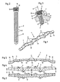
- the implant for osteosynthesis shown in the drawings consists of a a plurality of longitudinally successive holes 3 provided plate 1 and usually several insertable through the holes 3 in the plate 1 through and in accordance with regulations Position in a bone 4 screwed screws 2. At least a majority of the Recording the screws 2 specific holes 3 are based on an imaginary center plane 5 of the plate 1 alternately offset outwardly arranged the central axes 6 of the holes 3 close with the imaginary center plane 5 of the plate 1 an acute angle W a.
- the holes 3 taper from the intended outer surface 7 of the Plate 1 starting conical.
- the screws 2 have one to those of the holes 3 gebifdeten Sections substantially corresponding, tapered to that with a thread 8 provided shaft 9 toward tapered head 10.
- the screw 2 is over the Head 10 non-positively and / or positively fixed in the holes 3.
- the side boundaries 11, 12 of the plate 1 essentially follow the staggered holes 3 and also. the outer contours of the holes 3.
- the plate 1 therefore has over the length in Top view seen on a substantially wavy course.
- the plate is 1 Seen in the longitudinal direction executed multiple wounds, wherein in the range of the individual Holes 3, the main orientation transverse to the longitudinal extent of the plate 1 in each case at least runs approximately at right angles to the central axis 6 of the corresponding hole 3.
- the one central portion 13 of the plate relative to the length of the nearest two holes 3 are facing the same side boundary 11 (or 12) of the plate 1.
- center section refers to a central part of the plate containing the center of the plate, this central section must 13 not always located exactly in the middle relative to the length of the plate 1 be.
- Middle section 13 between the holes x / 2 + 0.5 and x / 2-0.5.
- the advantage here is the construction so that the imaginary center plane 5 of the plate 1 and the center plane 5 of the central portion 13 of the plate 1 is.
- the plate 1 Seen from the side, the plate 1 is slightly bent, for example the distance of a chord laid by the plate ends 14 from the central portion 13 is approximately 2 mm can be.
- This longitudinal bend can also counteract the bending of a fracture, when a bending moment acts perpendicular to the underside of the plate. It is by this longitudinal bend a better adaptation to the geometry of the forearm bone become possible.
- the size of the cross-sectional area of the plate 1 is at least approximately over the entire Length constant.
- the cross-sectional area of the plate 1 in the region of the central portion 13 can be made larger than in the other sections of the plate 1. Straight In This middle section, which spans the fracture area, is thus an additional optimizer the torsional stiffness possible.
- the distance of the holes 3 in the longitudinal direction of the plate 1 seen from the plate ends 14th starting is consistent. However, it may be the distance between the two to the Middle section 13 subsequent holes 3 be greater. Depending on the application or special Circumstances it is also conceivable to make the hole spacing variable.
- each hole 3 near the Side boundaries 11, 12 cantilevered cams 17 may be formed. These cams 17 may be advantageous in mounting the plate to thereby provide a corresponding gap between the bone surface and the plate 1. In the final state, however the plate 1 is not pressed against the surface of the bone 4, so that the cams without Pressure rest and practically only secure the distance during assembly itself. By the Screwing the screws themselves is in no way a pressing of the plate to the surface of the bone.
- the plate 1 and advantageously also the screw 2 are made of fiber-reinforced thermoplastics produced.
- the production can be done in a pressing process, for example in a Extrusion molding or in a push-pull extrusion process, carried out.
- the anisotropy of the elastic properties according to the formula E modulus (longitudinal): modulus of elasticity (tangential) 0.3 to 0.7 adjustable.
- the optimum is an average value of 0.5.
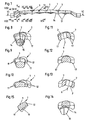
- tapered head 10 of the screw is provided in an optimal manner a fine thread.
- the head 10 the screw 2 in the region of the thread 18 with one or more longitudinal groove (s) provided is a way to accommodate tissue debris created.
- the screw 2 is on its threaded end 8 shank 9 in cross-section out of round, e.g. trilobular, executed.
- Such cross-sectional shapes are usually referred to as "equal thickness" Im
- the head 10 of the screw 2 is provided with an internal tool attack 19, which is for the Mounting and also for the disassembly of such screws is advantageous.
- An advantageous Design sees an internal tool attack 19 with four of a central opening radially outwardly led arcuate bulges before. That way is one very favorable transmission of the torque possible.
Landscapes
- Health & Medical Sciences (AREA)
- Orthopedic Medicine & Surgery (AREA)
- Surgery (AREA)
- Life Sciences & Earth Sciences (AREA)
- Molecular Biology (AREA)
- Public Health (AREA)
- Engineering & Computer Science (AREA)
- Biomedical Technology (AREA)
- Heart & Thoracic Surgery (AREA)
- Medical Informatics (AREA)
- Neurology (AREA)
- Animal Behavior & Ethology (AREA)
- General Health & Medical Sciences (AREA)
- Nuclear Medicine, Radiotherapy & Molecular Imaging (AREA)
- Veterinary Medicine (AREA)
- Surgical Instruments (AREA)
- Prostheses (AREA)
- Coloring Foods And Improving Nutritive Qualities (AREA)
- Distillation Of Fermentation Liquor, Processing Of Alcohols, Vinegar And Beer (AREA)
- Oscillators With Electromechanical Resonators (AREA)
- Jellies, Jams, And Syrups (AREA)
- Materials For Medical Uses (AREA)
Applications Claiming Priority (3)
| Application Number | Priority Date | Filing Date | Title |
|---|---|---|---|
| DE19951760A DE19951760B4 (de) | 1999-10-27 | 1999-10-27 | Implantat für Osteosynthesen |
| DE19951760 | 1999-10-27 | ||
| PCT/EP2000/010465 WO2001030251A1 (de) | 1999-10-27 | 2000-10-24 | Implantat für osteosynthesen |
Publications (2)
| Publication Number | Publication Date |
|---|---|
| EP1233713A1 EP1233713A1 (de) | 2002-08-28 |
| EP1233713B1 true EP1233713B1 (de) | 2004-08-18 |
Family
ID=7927059
Family Applications (1)
| Application Number | Title | Priority Date | Filing Date |
|---|---|---|---|
| EP00972856A Expired - Lifetime EP1233713B1 (de) | 1999-10-27 | 2000-10-24 | Implantat für osteosynthesen |
Country Status (8)
| Country | Link |
|---|---|
| US (1) | US6786909B1 (enExample) |
| EP (1) | EP1233713B1 (enExample) |
| JP (1) | JP4361709B2 (enExample) |
| AT (1) | ATE273662T1 (enExample) |
| AU (1) | AU1144201A (enExample) |
| CA (1) | CA2388854C (enExample) |
| DE (2) | DE19951760B4 (enExample) |
| WO (1) | WO2001030251A1 (enExample) |
Families Citing this family (56)
| Publication number | Priority date | Publication date | Assignee | Title |
|---|---|---|---|---|
| DE19951760B4 (de) | 1999-10-27 | 2005-06-09 | Sepitec Foundation | Implantat für Osteosynthesen |
| ATE274857T1 (de) * | 1999-12-06 | 2004-09-15 | Synthes Ag | Resorbierbare knochenplatte |
| US20050240187A1 (en) | 2004-04-22 | 2005-10-27 | Huebner Randall J | Expanded fixation of bones |
| US7717945B2 (en) | 2002-07-22 | 2010-05-18 | Acumed Llc | Orthopedic systems |
| AR038680A1 (es) | 2002-02-19 | 2005-01-26 | Synthes Ag | Implante intervertebral |
| ES2393099T3 (es) | 2003-02-06 | 2012-12-18 | Synthes Gmbh | Implante intervertebral |
| US7819903B2 (en) | 2003-03-31 | 2010-10-26 | Depuy Spine, Inc. | Spinal fixation plate |
| CN100553577C (zh) * | 2003-06-20 | 2009-10-28 | 精密医疗责任有限公司 | 用于在手术中对接骨板攻螺纹的系统 |
| WO2005013840A1 (de) * | 2003-08-08 | 2005-02-17 | Synthes Gmbh | Klemmvorrichtung |
| US7131860B2 (en) | 2003-11-20 | 2006-11-07 | Sherwood Services Ag | Connector systems for electrosurgical generator |
| US20050131407A1 (en) * | 2003-12-16 | 2005-06-16 | Sicvol Christopher W. | Flexible spinal fixation elements |
| US7942913B2 (en) | 2004-04-08 | 2011-05-17 | Ebi, Llc | Bone fixation device |
| US7527640B2 (en) | 2004-12-22 | 2009-05-05 | Ebi, Llc | Bone fixation system |
| ATE464011T1 (de) * | 2005-03-24 | 2010-04-15 | Medartis Ag | Knochenplatte |
| US7955364B2 (en) | 2005-09-21 | 2011-06-07 | Ebi, Llc | Variable angle bone fixation assembly |
| CN102172332A (zh) * | 2005-10-25 | 2011-09-07 | 圣歌整形外科有限责任公司 | 骨固定组件及与其一起使用的套管和螺钉 |
| US8551145B2 (en) * | 2005-12-19 | 2013-10-08 | Mayo Foundation For Medical Education And Research | Anterior adherent thoracolumbar spine plate |
| US8100952B2 (en) * | 2005-12-22 | 2012-01-24 | Anthem Orthopaedics Llc | Drug delivering bone plate and method and targeting device for use therewith |
| WO2007098288A2 (en) | 2006-02-27 | 2007-08-30 | Synthes (U.S.A.) | Intervertebral implant with fixation geometry |
| US7780685B2 (en) * | 2006-11-09 | 2010-08-24 | Ethicon Endo-Surgery, Inc. | Adhesive and mechanical fastener |
| DE202006019220U1 (de) | 2006-12-19 | 2007-05-24 | Zrinski Ag | Orthopädisches Schraubenverschlusssystem |
| US8142432B2 (en) * | 2007-02-05 | 2012-03-27 | Synthes Usa, Llc | Apparatus for repositioning portions of fractured bone and method of using same |
| US9072548B2 (en) * | 2007-06-07 | 2015-07-07 | Anthem Orthopaedics Llc | Spine repair assembly |
| WO2009064644A1 (en) | 2007-11-16 | 2009-05-22 | Synthes(U.S.A.) | Low profile intervertebral implant |
| WO2009099963A2 (en) * | 2008-01-31 | 2009-08-13 | Cayenne Medical, Inc | Self-tapping biocompatible interference bone screw |
| US9107712B2 (en) * | 2008-09-15 | 2015-08-18 | Biomet C.V. | Bone plate system for hand fractures and other small bones |
| JP5681636B2 (ja) | 2008-11-07 | 2015-03-11 | ジンテス ゲゼルシャフト ミット ベシュレンクテル ハフツング | 脊椎椎体間スペーサ及び連結プレートアセンブリ |
| US8728133B2 (en) | 2009-06-30 | 2014-05-20 | The Penn State Research Foundation | Bone repair system and method |
| US8808333B2 (en) * | 2009-07-06 | 2014-08-19 | Zimmer Gmbh | Periprosthetic bone plates |
| US8834532B2 (en) * | 2009-07-07 | 2014-09-16 | Zimmer Gmbh | Plate for the treatment of bone fractures |
| SM200900081B (it) * | 2009-10-05 | 2010-11-12 | Hit Medica S P A | Sistema placche per osteosintesi con viti pluriassiali a stabilità angolare in materiale polimerico. |
| US20110218580A1 (en) | 2010-03-08 | 2011-09-08 | Stryker Trauma Sa | Bone fixation system with curved profile threads |
| EP2654626B1 (en) | 2010-12-21 | 2016-02-24 | Synthes GmbH | Intervertebral implants and systems |
| US9241809B2 (en) | 2010-12-21 | 2016-01-26 | DePuy Synthes Products, Inc. | Intervertebral implants, systems, and methods of use |
| JP2014525776A (ja) | 2011-06-30 | 2014-10-02 | ロリオ,モーガン,パッカード | 脊椎プレート及びその使用方法 |
| US8632574B2 (en) * | 2011-12-07 | 2014-01-21 | Biomet C.V. | Reduced component bone plating system |
| US8790378B2 (en) | 2012-02-02 | 2014-07-29 | Biomet C.V. | Distal radius fracture fixation plate with integrated and adjustable volar ulnar facet support |
| US20150105829A1 (en) * | 2012-05-22 | 2015-04-16 | Austofix Group Limited | Bone fixation device |
| US20150238233A1 (en) * | 2012-08-09 | 2015-08-27 | Trinity Orthopedics, Llc | Intervertebral Plate Systems and Methods of Use |
| US10231767B2 (en) | 2013-03-15 | 2019-03-19 | The Penn State Research Foundation | Bone repair system, kit and method |
| US9510880B2 (en) * | 2013-08-13 | 2016-12-06 | Zimmer, Inc. | Polyaxial locking mechanism |
| US9987061B2 (en) * | 2014-01-28 | 2018-06-05 | Biomet C.V. | Implant with suspended locking holes |
| JP6735529B2 (ja) * | 2014-07-09 | 2020-08-05 | 国立大学法人東海国立大学機構 | 橈骨遠位端骨折治療用ロッキングプレートシステム |
| EP3169425B1 (en) | 2014-07-18 | 2022-08-31 | Sartorius Stedim Biotech GmbH | Membrane with increased surface area |
| US9730686B2 (en) | 2014-09-03 | 2017-08-15 | Biomet C.V. | System and method of soft tissue anchoring to metaphyseal bone plate |
| US9763705B2 (en) * | 2014-10-03 | 2017-09-19 | Globus Medical, Inc. | Orthopedic stabilization devices and methods for installation thereof |
| US9867718B2 (en) | 2014-10-22 | 2018-01-16 | DePuy Synthes Products, Inc. | Intervertebral implants, systems, and methods of use |
| EP3242617B1 (en) | 2015-01-07 | 2022-08-17 | Treace Medical Concepts, Inc. | Bone plating system |
| WO2016134160A1 (en) | 2015-02-18 | 2016-08-25 | Treace Medical Concepts, Inc. | Bone plating kit for foot and ankle applications |
| US10058363B2 (en) * | 2015-09-07 | 2018-08-28 | Karl Leibinger Medizintechnik Gmbh & Co Kg | Rib fixation system |
| EP3178423B1 (en) * | 2015-12-10 | 2018-02-21 | Stryker European Holdings I, LLC | Bone plate with polyaxial locking mechanism |
| US10357293B2 (en) * | 2016-02-02 | 2019-07-23 | Stryker European Holdings I, Llc | Bone plate with alternating chamfers |
| US11583323B2 (en) | 2018-07-12 | 2023-02-21 | Treace Medical Concepts, Inc. | Multi-diameter bone pin for installing and aligning bone fixation plate while minimizing bone damage |
| JP2019055232A (ja) * | 2018-11-27 | 2019-04-11 | 国立大学法人名古屋大学 | 橈骨遠位端骨折治療用ロッキングプレートシステム |
| EP3747384B1 (en) | 2019-06-03 | 2022-12-14 | Stryker European Holdings I, LLC | Rib plate and rib plate system |
| US11890039B1 (en) | 2019-09-13 | 2024-02-06 | Treace Medical Concepts, Inc. | Multi-diameter K-wire for orthopedic applications |
Family Cites Families (14)
| Publication number | Priority date | Publication date | Assignee | Title |
|---|---|---|---|---|
| FR742618A (enExample) * | 1933-03-10 | |||
| CH613858A5 (enExample) * | 1977-04-22 | 1979-10-31 | Straumann Inst Ag | |
| GB8515870D0 (en) * | 1985-06-22 | 1985-07-24 | Showell A W Sugicraft Ltd | Bone fixation plates |
| US4776330A (en) * | 1986-06-23 | 1988-10-11 | Pfizer Hospital Products Group, Inc. | Modular femoral fixation system |
| DE8628766U1 (de) * | 1986-10-25 | 1986-12-11 | Mecron Medizinische Produkte Gmbh, 1000 Berlin | Knochenplatte |
| EP0340223A1 (en) * | 1987-11-03 | 1989-11-08 | Synthes AG, Chur | Implant for osteosynthesis |
| JPH066810Y2 (ja) | 1989-11-29 | 1994-02-23 | 旭光学工業株式会社 | 椎体固定用プレート |
| EP0599640B1 (en) * | 1992-11-25 | 1998-08-26 | CODMAN & SHURTLEFF INC. | Osteosynthesis plate system |
| DE69514257T2 (de) * | 1994-02-21 | 2000-08-31 | Collux Ab, Falsterbo | Implantat für die Behandlung von Frakturen des Femur |
| ATE204230T1 (de) * | 1994-12-19 | 2001-09-15 | Sepitec Foundation | Verfahren zur herstellung von bauteilen aus faserverstärkten thermoplasten sowie nach dem verfahren hergestellter bauteil |
| WO1997009000A1 (de) * | 1995-09-06 | 1997-03-13 | Synthes Ag Chur | Knochenplatte |
| US5647712A (en) * | 1996-05-09 | 1997-07-15 | Fleetguard, Inc. | One directional socket-driven component |
| US6454769B2 (en) * | 1997-08-04 | 2002-09-24 | Spinal Concepts, Inc. | System and method for stabilizing the human spine with a bone plate |
| DE19951760B4 (de) | 1999-10-27 | 2005-06-09 | Sepitec Foundation | Implantat für Osteosynthesen |
-
1999
- 1999-10-27 DE DE19951760A patent/DE19951760B4/de not_active Expired - Fee Related
-
2000
- 2000-10-24 CA CA002388854A patent/CA2388854C/en not_active Expired - Fee Related
- 2000-10-24 US US10/111,224 patent/US6786909B1/en not_active Expired - Lifetime
- 2000-10-24 DE DE50007518T patent/DE50007518D1/de not_active Expired - Lifetime
- 2000-10-24 AU AU11442/01A patent/AU1144201A/en not_active Abandoned
- 2000-10-24 JP JP2001532674A patent/JP4361709B2/ja not_active Expired - Fee Related
- 2000-10-24 AT AT00972856T patent/ATE273662T1/de active
- 2000-10-24 EP EP00972856A patent/EP1233713B1/de not_active Expired - Lifetime
- 2000-10-24 WO PCT/EP2000/010465 patent/WO2001030251A1/de not_active Ceased
Also Published As
| Publication number | Publication date |
|---|---|
| DE50007518D1 (en) | 2004-09-23 |
| ATE273662T1 (de) | 2004-09-15 |
| JP2003512125A (ja) | 2003-04-02 |
| EP1233713A1 (de) | 2002-08-28 |
| CA2388854C (en) | 2008-07-29 |
| CA2388854A1 (en) | 2001-05-03 |
| AU1144201A (en) | 2001-05-08 |
| DE19951760A1 (de) | 2001-06-28 |
| DE19951760B4 (de) | 2005-06-09 |
| US6786909B1 (en) | 2004-09-07 |
| JP4361709B2 (ja) | 2009-11-11 |
| WO2001030251A1 (de) | 2001-05-03 |
Similar Documents
| Publication | Publication Date | Title |
|---|---|---|
| EP1233713B1 (de) | Implantat für osteosynthesen | |
| EP1175181B1 (de) | Verblockbare knochenplatte | |
| EP1865862B1 (de) | Pedikelschraube | |
| EP1608278B1 (de) | Aufnahme für ein verblockungselement und verblockungselement | |
| DE4343117C2 (de) | Fixationssystem für Knochen | |
| EP1613227B1 (de) | Osteosyntheseplatte zur operativen versorgung von knochenfrakturen | |
| EP1389963B1 (de) | Knochenplatte zur fixation von proximalen humerusfrakturen | |
| EP1246578B1 (de) | Knochenschraube | |
| EP1545357B1 (de) | System für die osteosynthese | |
| EP1622527B1 (de) | Implantat mit einem fixierkörper für eine knochenschraube | |
| EP1684651A1 (de) | Platte zum stabilisieren distaler radiusfrakturen | |
| EP2588015B1 (de) | Fixationssystem für knochen | |
| EP2844169B1 (de) | Knochenplattensystem für osteosynthese | |
| DE9321544U1 (de) | Osteosynthetische Platte | |
| CH695478A5 (de) | Gewindebolzen, Pedrikelschraube und Pedrikelschraube mit Gewindebolzen | |
| WO2007048267A1 (de) | Gewinde formende schraube | |
| EP1096891B1 (de) | Knochenschraube | |
| DE102005004841B4 (de) | Osteosyntheseplatte mit einer Vielzahl von Bohrungen zur Aufnahme von Knochenschrauben | |
| EP0903113A2 (de) | Winkelstabile Schraubenverbindung für Knochenplatten | |
| WO2001082809A1 (de) | Konturierte knochenplatte | |
| DE202007002190U1 (de) | Teilzylindrische Knochenplatte zur winkelstabilen Fixation | |
| EP0589235B1 (de) | Marknagel mit Arretierungsbolzen | |
| EP0472017A1 (de) | Zylindrischer Körper mit an der Aussenfläche ausgeformtem Gewinde | |
| DE10320124B3 (de) | Osteosyntheseplatte, insbesondere winkelstabile Radiusplatte, zur operativen Versorgung von Knochenfrakturen | |
| DE9004717U1 (de) | Osteosynthese-Platte |
Legal Events
| Date | Code | Title | Description |
|---|---|---|---|
| PUAI | Public reference made under article 153(3) epc to a published international application that has entered the european phase |
Free format text: ORIGINAL CODE: 0009012 |
|
| 17P | Request for examination filed |
Effective date: 20020522 |
|
| AK | Designated contracting states |
Kind code of ref document: A1 Designated state(s): AT BE CH CY DE DK ES FI FR GB GR IE IT LI LU MC NL PT SE |
|
| AX | Request for extension of the european patent |
Free format text: AL PAYMENT 20020522;LT PAYMENT 20020522;LV PAYMENT 20020522;MK PAYMENT 20020522;RO PAYMENT 20020522;SI PAYMENT 20020522 |
|
| GRAP | Despatch of communication of intention to grant a patent |
Free format text: ORIGINAL CODE: EPIDOSNIGR1 |
|
| GRAS | Grant fee paid |
Free format text: ORIGINAL CODE: EPIDOSNIGR3 |
|
| GRAA | (expected) grant |
Free format text: ORIGINAL CODE: 0009210 |
|
| AK | Designated contracting states |
Kind code of ref document: B1 Designated state(s): AT BE CH CY DE DK ES FI FR GB GR IE IT LI LU MC NL PT SE |
|
| AX | Request for extension of the european patent |
Extension state: AL LT LV MK RO SI |
|
| PG25 | Lapsed in a contracting state [announced via postgrant information from national office to epo] |
Ref country code: IE Free format text: LAPSE BECAUSE OF FAILURE TO SUBMIT A TRANSLATION OF THE DESCRIPTION OR TO PAY THE FEE WITHIN THE PRESCRIBED TIME-LIMIT Effective date: 20040818 Ref country code: CY Free format text: LAPSE BECAUSE OF FAILURE TO SUBMIT A TRANSLATION OF THE DESCRIPTION OR TO PAY THE FEE WITHIN THE PRESCRIBED TIME-LIMIT Effective date: 20040818 Ref country code: ES Free format text: LAPSE BECAUSE OF FAILURE TO SUBMIT A TRANSLATION OF THE DESCRIPTION OR TO PAY THE FEE WITHIN THE PRESCRIBED TIME-LIMIT Effective date: 20040818 |
|
| REG | Reference to a national code |
Ref country code: GB Ref legal event code: FG4D Free format text: NOT ENGLISH |
|
| REG | Reference to a national code |
Ref country code: CH Ref legal event code: EP |
|
| REG | Reference to a national code |
Ref country code: IE Ref legal event code: FG4D Free format text: GERMAN |
|
| REF | Corresponds to: |
Ref document number: 50007518 Country of ref document: DE Date of ref document: 20040923 Kind code of ref document: P |
|
| PG25 | Lapsed in a contracting state [announced via postgrant information from national office to epo] |
Ref country code: LU Free format text: LAPSE BECAUSE OF NON-PAYMENT OF DUE FEES Effective date: 20041024 |
|
| REG | Reference to a national code |
Ref country code: CH Ref legal event code: NV Representative=s name: RIEDERER HASLER & PARTNER PATENTANWAELTE AG |
|
| PG25 | Lapsed in a contracting state [announced via postgrant information from national office to epo] |
Ref country code: BE Free format text: LAPSE BECAUSE OF NON-PAYMENT OF DUE FEES Effective date: 20041031 Ref country code: MC Free format text: LAPSE BECAUSE OF NON-PAYMENT OF DUE FEES Effective date: 20041031 |
|
| PG25 | Lapsed in a contracting state [announced via postgrant information from national office to epo] |
Ref country code: GR Free format text: LAPSE BECAUSE OF FAILURE TO SUBMIT A TRANSLATION OF THE DESCRIPTION OR TO PAY THE FEE WITHIN THE PRESCRIBED TIME-LIMIT Effective date: 20041118 Ref country code: DK Free format text: LAPSE BECAUSE OF FAILURE TO SUBMIT A TRANSLATION OF THE DESCRIPTION OR TO PAY THE FEE WITHIN THE PRESCRIBED TIME-LIMIT Effective date: 20041118 |
|
| REG | Reference to a national code |
Ref country code: SE Ref legal event code: TRGR |
|
| GBT | Gb: translation of ep patent filed (gb section 77(6)(a)/1977) |
Effective date: 20041208 |
|
| LTIE | Lt: invalidation of european patent or patent extension |
Effective date: 20040818 |
|
| REG | Reference to a national code |
Ref country code: IE Ref legal event code: FD4D |
|
| BERE | Be: lapsed |
Owner name: SEPITEC FOUNDATION Effective date: 20041031 |
|
| PLBE | No opposition filed within time limit |
Free format text: ORIGINAL CODE: 0009261 |
|
| STAA | Information on the status of an ep patent application or granted ep patent |
Free format text: STATUS: NO OPPOSITION FILED WITHIN TIME LIMIT |
|
| ET | Fr: translation filed | ||
| 26N | No opposition filed |
Effective date: 20050519 |
|
| BERE | Be: lapsed |
Owner name: *SEPITEC FOUNDATION Effective date: 20041031 |
|
| PG25 | Lapsed in a contracting state [announced via postgrant information from national office to epo] |
Ref country code: PT Free format text: LAPSE BECAUSE OF NON-PAYMENT OF DUE FEES Effective date: 20050118 |
|
| PGFP | Annual fee paid to national office [announced via postgrant information from national office to epo] |
Ref country code: NL Payment date: 20081021 Year of fee payment: 9 |
|
| PGFP | Annual fee paid to national office [announced via postgrant information from national office to epo] |
Ref country code: FI Payment date: 20081002 Year of fee payment: 9 |
|
| PGFP | Annual fee paid to national office [announced via postgrant information from national office to epo] |
Ref country code: IT Payment date: 20081027 Year of fee payment: 9 Ref country code: SE Payment date: 20081014 Year of fee payment: 9 |
|
| REG | Reference to a national code |
Ref country code: NL Ref legal event code: V1 Effective date: 20100501 |
|
| EUG | Se: european patent has lapsed | ||
| PG25 | Lapsed in a contracting state [announced via postgrant information from national office to epo] |
Ref country code: NL Free format text: LAPSE BECAUSE OF NON-PAYMENT OF DUE FEES Effective date: 20100501 |
|
| PG25 | Lapsed in a contracting state [announced via postgrant information from national office to epo] |
Ref country code: FI Free format text: LAPSE BECAUSE OF NON-PAYMENT OF DUE FEES Effective date: 20091024 |
|
| PG25 | Lapsed in a contracting state [announced via postgrant information from national office to epo] |
Ref country code: IT Free format text: LAPSE BECAUSE OF NON-PAYMENT OF DUE FEES Effective date: 20091024 |
|
| PG25 | Lapsed in a contracting state [announced via postgrant information from national office to epo] |
Ref country code: SE Free format text: LAPSE BECAUSE OF NON-PAYMENT OF DUE FEES Effective date: 20091025 |
|
| REG | Reference to a national code |
Ref country code: DE Ref legal event code: R082 Ref document number: 50007518 Country of ref document: DE Representative=s name: SCHUMACHER & WILLSAU PATENTANWALTSGESELLSCHAFT, DE |
|
| REG | Reference to a national code |
Ref country code: FR Ref legal event code: PLFP Year of fee payment: 16 |
|
| REG | Reference to a national code |
Ref country code: CH Ref legal event code: NV Representative=s name: ISLER AND PEDRAZZINI AG, CH |
|
| REG | Reference to a national code |
Ref country code: FR Ref legal event code: PLFP Year of fee payment: 17 |
|
| REG | Reference to a national code |
Ref country code: FR Ref legal event code: PLFP Year of fee payment: 18 |
|
| PGFP | Annual fee paid to national office [announced via postgrant information from national office to epo] |
Ref country code: DE Payment date: 20171019 Year of fee payment: 18 Ref country code: FR Payment date: 20171024 Year of fee payment: 18 |
|
| PGFP | Annual fee paid to national office [announced via postgrant information from national office to epo] |
Ref country code: GB Payment date: 20171019 Year of fee payment: 18 Ref country code: CH Payment date: 20171011 Year of fee payment: 18 Ref country code: AT Payment date: 20171020 Year of fee payment: 18 |
|
| REG | Reference to a national code |
Ref country code: DE Ref legal event code: R119 Ref document number: 50007518 Country of ref document: DE |
|
| REG | Reference to a national code |
Ref country code: CH Ref legal event code: PL |
|
| REG | Reference to a national code |
Ref country code: AT Ref legal event code: MM01 Ref document number: 273662 Country of ref document: AT Kind code of ref document: T Effective date: 20181024 |
|
| GBPC | Gb: european patent ceased through non-payment of renewal fee |
Effective date: 20181024 |
|
| PG25 | Lapsed in a contracting state [announced via postgrant information from national office to epo] |
Ref country code: DE Free format text: LAPSE BECAUSE OF NON-PAYMENT OF DUE FEES Effective date: 20190501 |
|
| PG25 | Lapsed in a contracting state [announced via postgrant information from national office to epo] |
Ref country code: CH Free format text: LAPSE BECAUSE OF NON-PAYMENT OF DUE FEES Effective date: 20181031 Ref country code: FR Free format text: LAPSE BECAUSE OF NON-PAYMENT OF DUE FEES Effective date: 20181031 Ref country code: LI Free format text: LAPSE BECAUSE OF NON-PAYMENT OF DUE FEES Effective date: 20181031 |
|
| PG25 | Lapsed in a contracting state [announced via postgrant information from national office to epo] |
Ref country code: AT Free format text: LAPSE BECAUSE OF NON-PAYMENT OF DUE FEES Effective date: 20181024 Ref country code: GB Free format text: LAPSE BECAUSE OF NON-PAYMENT OF DUE FEES Effective date: 20181024 |