EP2844169B1 - Knochenplattensystem für osteosynthese - Google Patents
Knochenplattensystem für osteosynthese Download PDFInfo
- Publication number
- EP2844169B1 EP2844169B1 EP13719713.3A EP13719713A EP2844169B1 EP 2844169 B1 EP2844169 B1 EP 2844169B1 EP 13719713 A EP13719713 A EP 13719713A EP 2844169 B1 EP2844169 B1 EP 2844169B1
- Authority
- EP
- European Patent Office
- Prior art keywords
- screw
- hole
- bone
- bone plate
- head
- Prior art date
- Legal status (The legal status is an assumption and is not a legal conclusion. Google has not performed a legal analysis and makes no representation as to the accuracy of the status listed.)
- Active
Links
- 210000000988 bone and bone Anatomy 0.000 title claims description 152
- 230000007704 transition Effects 0.000 description 7
- 239000012634 fragment Substances 0.000 description 4
- 208000010392 Bone Fractures Diseases 0.000 description 2
- 230000006378 damage Effects 0.000 description 2
- 238000005516 engineering process Methods 0.000 description 2
- 230000013011 mating Effects 0.000 description 2
- 238000000034 method Methods 0.000 description 2
- 238000010079 rubber tapping Methods 0.000 description 2
- 208000008924 Femoral Fractures Diseases 0.000 description 1
- 206010017076 Fracture Diseases 0.000 description 1
- 208000001164 Osteoporotic Fractures Diseases 0.000 description 1
- 230000006978 adaptation Effects 0.000 description 1
- 238000004873 anchoring Methods 0.000 description 1
- 230000015572 biosynthetic process Effects 0.000 description 1
- 230000000295 complement effect Effects 0.000 description 1
- 230000006835 compression Effects 0.000 description 1
- 238000007906 compression Methods 0.000 description 1
- 230000001419 dependent effect Effects 0.000 description 1
- 230000000694 effects Effects 0.000 description 1
- 230000003203 everyday effect Effects 0.000 description 1
- 239000007943 implant Substances 0.000 description 1
- 230000003993 interaction Effects 0.000 description 1
- 230000001009 osteoporotic effect Effects 0.000 description 1
Images


Classifications
-
- A—HUMAN NECESSITIES
- A61—MEDICAL OR VETERINARY SCIENCE; HYGIENE
- A61B—DIAGNOSIS; SURGERY; IDENTIFICATION
- A61B17/00—Surgical instruments, devices or methods, e.g. tourniquets
- A61B17/56—Surgical instruments or methods for treatment of bones or joints; Devices specially adapted therefor
- A61B17/58—Surgical instruments or methods for treatment of bones or joints; Devices specially adapted therefor for osteosynthesis, e.g. bone plates, screws, setting implements or the like
- A61B17/68—Internal fixation devices, including fasteners and spinal fixators, even if a part thereof projects from the skin
- A61B17/80—Cortical plates, i.e. bone plates; Instruments for holding or positioning cortical plates, or for compressing bones attached to cortical plates
- A61B17/8052—Cortical plates, i.e. bone plates; Instruments for holding or positioning cortical plates, or for compressing bones attached to cortical plates immobilised relative to screws by interlocking form of the heads and plate holes, e.g. conical or threaded
- A61B17/8057—Cortical plates, i.e. bone plates; Instruments for holding or positioning cortical plates, or for compressing bones attached to cortical plates immobilised relative to screws by interlocking form of the heads and plate holes, e.g. conical or threaded the interlocking form comprising a thread
-
- A—HUMAN NECESSITIES
- A61—MEDICAL OR VETERINARY SCIENCE; HYGIENE
- A61B—DIAGNOSIS; SURGERY; IDENTIFICATION
- A61B17/00—Surgical instruments, devices or methods, e.g. tourniquets
- A61B17/56—Surgical instruments or methods for treatment of bones or joints; Devices specially adapted therefor
- A61B17/58—Surgical instruments or methods for treatment of bones or joints; Devices specially adapted therefor for osteosynthesis, e.g. bone plates, screws, setting implements or the like
- A61B17/68—Internal fixation devices, including fasteners and spinal fixators, even if a part thereof projects from the skin
- A61B17/80—Cortical plates, i.e. bone plates; Instruments for holding or positioning cortical plates, or for compressing bones attached to cortical plates
- A61B17/8033—Cortical plates, i.e. bone plates; Instruments for holding or positioning cortical plates, or for compressing bones attached to cortical plates having indirect contact with screw heads, or having contact with screw heads maintained with the aid of additional components, e.g. nuts, wedges or head covers
-
- A—HUMAN NECESSITIES
- A61—MEDICAL OR VETERINARY SCIENCE; HYGIENE
- A61B—DIAGNOSIS; SURGERY; IDENTIFICATION
- A61B17/00—Surgical instruments, devices or methods, e.g. tourniquets
- A61B17/56—Surgical instruments or methods for treatment of bones or joints; Devices specially adapted therefor
- A61B17/58—Surgical instruments or methods for treatment of bones or joints; Devices specially adapted therefor for osteosynthesis, e.g. bone plates, screws, setting implements or the like
- A61B17/68—Internal fixation devices, including fasteners and spinal fixators, even if a part thereof projects from the skin
- A61B17/80—Cortical plates, i.e. bone plates; Instruments for holding or positioning cortical plates, or for compressing bones attached to cortical plates
- A61B17/8052—Cortical plates, i.e. bone plates; Instruments for holding or positioning cortical plates, or for compressing bones attached to cortical plates immobilised relative to screws by interlocking form of the heads and plate holes, e.g. conical or threaded
-
- A—HUMAN NECESSITIES
- A61—MEDICAL OR VETERINARY SCIENCE; HYGIENE
- A61B—DIAGNOSIS; SURGERY; IDENTIFICATION
- A61B17/00—Surgical instruments, devices or methods, e.g. tourniquets
- A61B17/56—Surgical instruments or methods for treatment of bones or joints; Devices specially adapted therefor
- A61B17/58—Surgical instruments or methods for treatment of bones or joints; Devices specially adapted therefor for osteosynthesis, e.g. bone plates, screws, setting implements or the like
- A61B17/68—Internal fixation devices, including fasteners and spinal fixators, even if a part thereof projects from the skin
- A61B17/84—Fasteners therefor or fasteners being internal fixation devices
- A61B17/86—Pins or screws or threaded wires; nuts therefor
- A61B17/8605—Heads, i.e. proximal ends projecting from bone
Definitions
- the invention relates to technologies in the field of bone plate systems for osteosynthesis.
- Bone plate systems serve the angular stable fixation of a bone plate by means of associated screws for osteosynthesis on the human or animal body.
- Numerous bone plate systems are known which typically include a bone plate having an array of multiple through holes and associated screws.
- fixing screws may be provided, which in turn are not screwed into the bone, but rather in a thread formed in the bone plate.
- Such fastening screws then serve, for example, for fixing the bone screws (cf., for example, the documents EP 1 702 577 A2 . WO 2006/014436 A1 such as AT 406 446 B ).
- a fixing screw is used to fix several bone screws.
- WO 2005/041 796 A1 discloses a bone plate provided with oblong holes.
- Angularly stable plate-screw connections to osteosynthesis plates have the advantage of better anchoring of the bone plate to the bone. This is particularly advantageous for joint-near bone fractures, since in this way joint-near bone fragments can be better grasped and fixed.
- the advantage of angle-stable plate-screw connections is gaining in significance in osteoporotic fractures close to the joints, since bone screws without angular stability are less able to fix osteoporotic bone.
- Angular stable plate-screw connections can be divided into monoaxial and polyaxial plate-screw connections.
- Examples of monoaxial angularly stable plate-screw connections are in the documents DE 10 2005 004 841 B4 or DE 10 2005 043 285 B3 executed. These systems are characterized by having male threaded heads which engage in corresponding internal threads of plates. If a screw is screwed in during an operation, the positive connection between the external thread of the screw head and the internal thread of the bone plate causes an angle-stable plate-screw connection during the last turns of the screwing process.
- bone plate systems have been proposed in which bone screws are variable in terms of their pivotal or angular position with respect to the bone plate in use.
- a bone plate system is for example in the document DE 10 2006 000 948 A1 described.
- WO 2007/025520 A1 is a bone plate with at least one screw for angular stable fixation disclosed.
- Another example of a polyaxial angular stable plate-and-bolt connection is in DE 10 2005 042 766 B4 disclosed.
- the described therein formation of an internal thread of six internal threaded posts succeeds to screw ball screws with a special external thread in the polyaxial direction and to fix during the last turns of the screwing angle stable. Due to the clinical advantages of a polyaxial angle stable fixation option, such plate screw systems have become increasingly popular in everyday clinical practice.
- a device for angular stable fixation and compression of a fracture site on a bone is known.
- the known bone plate has several individual holes, in each of which a bone screw can be screwed. In connection with the individual holes can be provided that they have a sickle-like hole extension.
- the document WO 2009/058969 A1 also relates to a bone plate system in which the bone plate has a plurality of individual holes for receiving exactly one screw.
- the bone plate has a plurality of individual holes for receiving exactly one screw.
- pillars are provided with projections which in the screwed state of the respective screw with a thread on the screw head in Engage.
- the plurality of columns with projections are separated in the respective hole from each other by areas which are free of such projections and thus have a smooth surface.
- a bone plate system for osteosynthesis in which for fixing the bone plate on the bone in a pivot hole and a clamping screw in a clamping hole a clamping screw are screwed, such that in the screwed state, the pivoting screw and the clamping screw are fixed multi-dimensionally stable angle by the screw heads the pivoting screw and the clamping screw are secured against each other and with the bone plate against a relative movement, wherein the pivoting screw and the clamping screw are each designed as a bone screw.
- the object of the invention is to provide improved technologies for bone plate systems for osteosynthesis, with which the multi-dimensional angular stability of the introduced into the bone plate screws is optimized.
- a bulge is provided, which expands the through hole and is arranged opposite the opening.
- the bone screw and the further bone screw are fixed in a multi-dimensionally angularly stable manner by the screw heads of the bone screw and the further bone screw being secured against relative movement with one another and with the bone plate by means of a tensioned multipoint bearing.
- the tensioned multipoint bearing is formed in the through hole with attachments of the bone screw at transition areas between the bulge and the respective adjacent to the bulge through-hole portion.
- the transition regions are preferably formed as corner regions in which the bone screw comes into abutment in the screwed-in state. The bone screw is thereby clamped in the through hole at the two opposite transition areas.
- the radial projections and / or grooves are formed continuously from the edge of the bulge to the edge of the opening between the through hole and the further through hole, preferably in both halves of the through hole.
- the surface structure on the screw head can be positively engaged with the radial projections and / or grooves in the screwed-in state of the bone screw.
- the bulge is formed with a sickle shape.
- the outer shape of the bulge may correspond in one embodiment to a circular arc portion, wherein the associated radius of the circular arc portion is smaller than the radius of the through hole.
- the radius of the circular arc portion of the bulge is at most about 2/3 of the radius of the through hole. It is further preferred that the radius of the circular arc portion of the bulge corresponds to at most about 1/2 of the radius of the through hole.
- the bulge has a smooth surface.
- the bulge is free of radial projections and radial grooves. Also, no thread is provided in the bulge here.
- a straight-line distance between opposite ends of the bulge is smaller than the diameter of the through hole.
- the rectilinear distance is at most 2/3 of the diameter of the through-hole. It is further preferred that the straight-line distance between the opposite ends of the bulge is at most about half of the diameter of the through-hole.
- the through hole with a ball head receptacle opening toward the top of the bone plate and the screw head of the bone screw are formed as an associated ball head, which is at least partially arranged in the ball head receptacle of the through hole in the screwed-in state of the bone screw.
- the screw head of the bone screw insofar as it is received in the ball seat, can be arranged in a form-fitting manner therein.
- the further through hole may be formed with a ball head receptacle which opens toward the top of the bone plate, into which the screw head of the bone screw, which is formed as an associated ball head, engages in the screwed-in state.
- both the bone screw and the further bone screw are formed with a ball head, which is arranged in the screwed state each in a ball head socket.
- the ball head is provided with a first and a second thread, which are formed superimposed on the ball head.
- the first and the second thread may be, for example, a right-hand and a left-hand thread.
- a further thread and / or horizontal circumferential grooves may be provided on the ball head.
- clamping hole and pivot hole generally relate to a through hole and another through hole.
- a training provides that the bone plate is formed with an extension region adjacent to the clamping hole, such that the bone plate at least partially yielding and free of Einschraubtik due to the interaction between the external thread and the internal thread when screwing the clamping screw in the internal thread of the clamping hole plastic deformation is deformable.
- the expansion region providing embodiment is preferably carried out such that the external thread is formed as a conical external thread and the internal thread as a cylindrical internal thread.
- the clamping screw can optionally be completely screwed into the through hole with the screw head.
- the screw head is held on the one hand by the elastic tension in each position against rotation on the one hand, on the other hand, but the bone plate is not irreversibly deformed in their plastic range, d. H. overstretched.
- the clamping screw can be sensitively screwed in just as far as it is necessary to firmly fix the bone plate to the bone and to achieve the clamping with the swivel screw, while ensuring that the screw head in his In the most elevated areas, the bone plate is not projected so that the fixed bone plate as a whole forms - with the clamping screw - a unit which essentially fits snugly against the bone without elevations.
- the adjacent expansion region is at least partially formed as a web or part of a ring.
- the screw shank has a length which is equal to or shorter than the length of the screw shank of the swivel screw.
- the length of the shank of the clamping screw is at most half, preferably at most one third of the length of the shank of the swivel screw.
- the length of the shank of the clamping screw shortened in relation to the screw shank of the swivel screw supports, in particular, the versatility of the swivel or angular positions of the swivel screw with respect to the bone plate.
- the shaft of the pivoting screw can also be pivoted in an area below the lower shaft end of the clamping screw.
- a training provides that in the bone plate at least one further the pivot hole or the clamping hole executed and corresponding to the pivot hole and the clamping hole through hole is formed, that in the further through hole another bone screw is inserted, which performed the pivoting screw or the clamping screw accordingly is, and that the screw head of the other bone screw in the screwed state with the screw heads, such as the ball head and the screw head with conical external thread, and the bone plate is clamped.
- an arrangement of at least three mutually associated through holes is formed, in which a respective bone screw is screwed. It can be provided any combination of swivel screws and clamping screws, optionally threaded portions of the screw heads of the involved bone screws mesh positively in pairs and thus support each other and are jointly secured to the bone plate against relative movement.
- the pivot hole and the associated clamping hole may be part of a so-called plate hole group with further through holes or these form.
- the bone plate may have multiple plate hole groups. Additional through holes can be formed as round or oblong holes for accurate recording of round, countersunk, spherical, lens, bulb or cone head screws.
- a particularly advantageous for the bone plate swivel screw has a spherical screw head, which is flattened at the head (north).
- a preferred clamping screw is designed as a countersunk screw with a cylindrical thread below the countersunk head.
- the shape of the lower surface of the countersunk screw can be rounded in this case to improve the contact surface and be designed to match the spherical shape of the Schwenkschraubenkopfes.
- the length of the cylindrical thread of the bolt is a multiple of the plate thickness, for example, 0.9 times. hereby
- the cylindrical thread of the clamping screw can first securely grasp in the cylindrical mating thread of the plate and press the pivoting screw in its planned course in the further course of screwing, so that the greatest possible clamping effect is provided. This is particularly advantageous for slightly tilted swivel screws.
- the cylinder thread of the clamping screw slightly projects beyond the lower surface of the bone plate, and therefore the beginning of the screw tip-side cylinder thread can be designed as a self-tapping thread, so that the cylinder thread can penetrate slightly into the bone to be screwed.
- the further, usually longer, screw-tip portion of the bolt of the clamping screw is typically designed like a bone screw with a self-tapping thread.
- the external thread of the clamping screw which is to take in the mating thread of the bone plate may be formed as a cone thread, wherein the inclination angle of the cone to the longitudinal axis of the screw fails less than the inclination angle of the countersunk head.
- the swivel screw can be first poly-axially screwed in the application, which makes it possible to fix bone fragments and to pull on the plate. Subsequently, the clamping screw can be screwed in and fix at the same time self-locking and the pivoting screw during the last turns angle stable.
- the clamping screw itself acts as a monoaxial angle stable screw.
- the thread may advantageously have rounded tips.
- the surface of the swivel screw is designed such that the round head surface of the swivel screw perpendicular to the equator of the screw head has longitudinal segments, for example, twelve length segments. Each longitudinal segment is designed with a réellespitzgewindeklade to serve as a positive abutment for the clamping screw.
- the clamping screw has a conical outer point thread, which on the one hand allows positive locking of the plate via a conical inner point thread of the clamping hole.
- the swivel screw is fixed in a form-fitting manner via its female threaded posts on the screw head.
- the internal thread columns on the pivoting screw for example, formed such that the surface of the screw head portion of the pivot screw still has enough spherical surface, so that no thread destruction or burring occurs during tightening of the pivoting screw.
- the surface of the pivot hole may be equipped with at least one réellespitzgewindeklave to give the mounting a higher angular stability.
- the swivel screw can also be equipped with preferably twelve internally threaded columns, said internal pointed threaded columns can advantageously be formed on the surface of the swivel hole with an adapted or passable thread form.
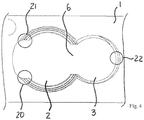
- Fig. 4 shows a schematic representation of a tensioned three-point bearing.
- Circles 20, 21 and 22 symbolize the attachment of the screw head 9 of the bone screw 10 in the corner regions 14, 15 in the through hole 2 on the one hand and an attachment of the screw head 11 of the other bone screw 12 in the further through hole 3 the opening 6 opposite.
- Another triangular tension results between the deposits in the corner areas on the one hand and the contact between the screw heads 9, 11 of the bone screw 10 and the further bone screw 12 (not shown in FIG Fig. 4 ).
Description
- Die Erfindung betrifft Technologien auf dem Gebiet der Knochenplattensysteme für die Osteosynthese.
- Knochenplattensysteme dienen dem winkelstabilen Fixieren einer Knochenplatte mittels zugeordneter Schrauben zur Osteosynthese am menschlichen oder tierischen Körper. Zahlreiche Knochenplattensysteme sind bekannt, die üblicherweise eine Knochenplatte mit einer Anordnung von mehreren Durchgangslöchern sowie zugehörige Schrauben umfassen. Hierbei können zusätzlich zu sogenannten Knochenschrauben, also Schrauben, die beim Fixieren in den Knochen eingedreht werden, Befestigungsschrauben vorgesehen sein, die ihrerseits nicht in den Knochen eingedreht werden, sondern vielmehr in ein in der Knochenplatte gebildetes Gewinde. Derartige Befestigungsschrauben dienen dann beispielsweise zur Fixierung der Knochenschrauben (vgl. zum Beispiel die Dokumente
EP 1 702 577 A2 ,WO 2006 / 014436 A1 sowieAT 406 446 B DE 698 35 968 T2 wird eine Befestigungsschraube zum Fixieren mehrerer Knochenschrauben genutzt. - Im Dokument
WO 2005 / 041 796 A1 ist eine Knochenplatte offenbart, die mit Langlöchern versehen ist. - Winkelstabile Platten-Schrauben-Verbindungen an Osteosyntheseplatten haben den Vorteil einer besseren Verankerung der Knochenplatte an den Knochen. Dies ist besonders bei gelenknahen Knochenbrüchen von Vorteil, da auf diese Art und Weise gelenknahe Knochenfragmente besser gefasst und fixiert werden können. Der Vorteil winkelstabiler Platten-Schrauben-Verbindungen gewinnt bei osteoporotischen gelenknahen Knochenbrüchen an Bedeutung, da Knochenschrauben ohne Winkelstabilität einen osteoporotischen Knochen schlechter fixieren können.
- Winkelstabile Platten-Schrauben-Verbindungen können in monoaxiale und polyaxiale Platten-Schrauben-Verbindungen unterteilt werden.
- Beispiele monoaxialer winkelstabiler Platten-Schrauben-Verbindungen sind in den Dokumenten
DE 10 2005 004 841 B4 oderDE 10 2005 043 285 B3 ausgeführt. Diese Systeme sind dadurch gekennzeichnet, dass sie Schraubenköpfe mit Außengewinde aufweisen, welche in korrespondierende Innengewinde von Platten greifen. Wird eine Schraube während einer Operation eingeschraubt, bewirkt der Formschluss zwischen Außengewinde des Schraubenkopfes und Innengewinde der Knochenplatte eine winkelstabile Platten-Schrauben-Verbindung während der letzten Umdrehungen des Einschraubvorgangs. - Weiterhin wurden Knochenplattensysteme vorgeschlagen, bei denen Knochenschrauben hinsichtlich ihrer Schwenk- oder Winkelstellung in Bezug auf die Knochenplatte beim Einsatz variabel sind. Ein solches Knochenplattensystem ist beispielsweise in dem Dokument
DE 10 2006 000 948 A1 beschrieben. Im DokumentWO 2007 / 025520 A1 ist eine Knochenplatte mit mindestens einer Schraube zur winkelstabilen Fixierung offenbart. Ein weiteres Beispiel einer polyaxialen winkelstabilen Platten-Schrauben-Verbindungen ist inDE 10 2005 042 766 B4 offenbart. Durch die dort beschrieben Ausbildung eines Innengewindes aus sechs Innengewindesäulen gelingt es, Kugelkopfschrauben mit einem besonderen Außengewinde in polyaxialer Richtung einzuschrauben und während der letzten Umdrehungen des Einschraubvorgangs winkelstabil zu fixieren. Aufgrund klinischer Vorteile einer polyaxialen winkelstabilen Fixierungsmöglichkeit haben sich derartige Platten-Schrauben-Systeme im klinischen Alltag immer mehr durchgesetzt. - Aus dem Dokument
WO 2010 / 115403 A1 ist eine Vorrichtung zur winkelstabilen Fixation und Kompression einer Bruchstelle an einem Knochen bekannt. Die bekannte Knochenplatte verfügt über mehrere Einzellöcher, in die jeweils eine Knochenschraube einschraubbar ist. In Verbindung mit den Einzellöchern kann vorgesehen sein, dass diese über eine sichelartige Locherweiterung verfügen. - Das Dokument
WO 2009 / 058969 A1 betrifft ebenfalls ein Knochenplattensystem, bei dem die Knochenplatte über mehrere Einzellöcher zur jeweiligen Aufnahme von genau einer Schraube verfügt. In den Durchgangslöchern sind Säulen mit Vorsprüngen vorgesehen, die im eingeschraubten Zustand der jeweiligen Schraube mit einem Gewinde am Schraubenkopf im Eingriff stehen. Die mehreren Säulen mit Vorsprüngen sind in dem jeweiligen Loch voneinander durch Bereiche getrennt, die frei von derartigen Vorsprüngen sind und insoweit eine glatte Oberfläche aufweisen. - Aus dem Dokument
WO 2011 / 076205 A1 ist weiterhin ein Knochenplattensystem für die Osteosynthese bekannt, bei dem zum Fixieren der Knochenplatte am Knochen in ein Schwenkloch eine Schwenkschraube und in ein Klemmloch eine Klemmschraube eingeschraubt werden, derart, dass im eingeschraubten Zustand die Schwenkschraube und die Klemmschraube mehrdimensional winkelstabil fixiert sind, indem die Schraubenköpfe der Schwenkschraube und der Klemmschraube untereinander sowie mit der Knochenplatte gegen eine Relativbewegung gesichert sind, wobei die Schwenkschraube und die Klemmschraube jeweils als eine Knochenschraube ausgeführt sind. - Weiterhin offenbart Dokument
DE 10 2007 005 417 A1 ein Plattenimplantat zur Anwendung an der Wirbelsäule, bei dem Knochenschrauben in ein jeweils zugeordnetes Durchgangsloch eingeschraubt werden. Der Schraubenkopf der Knochenschrauben ist mit einem Gewinde versehen, die im eingeschraubten Zustand mit Schnittlinien oder Schnittflächen in dem jeweils zugeordneten Durchgangsloch zusammenwirken. - Aufgabe der Erfindung ist es, verbesserte Technologien für Knochenplattensysteme zur Osteosynthese anzugeben, mit denen die mehrdimensionale Winkelstabilität der in die Knochenplatte eingeführten Schrauben optimiert ist.
- Diese Aufgabe wird durch ein Knochenplattensystem zur Osteosynthese nach dem unabhängigen Anspruch 1 gelöst. Ausgestaltungen sind Gegenstand von abhängigen Unteransprüchen.
- Es ist ein Knochenplattensystem zur Osteosynthese mit einer Knochenplatte, einer Knochenschraube, deren Schraubenkopf wenigstens abschnittsweise eine Oberflächenstruktur aufweist, und einer weiteren Knochenschraube vorgesehen, deren Schraubenkopf wenigstens abschnittsweise eine Oberflächenstruktur aufweist. Die Knochenplatte weist ein Durchgangsloch, welches geeignet ist, die Knochenschraube polyaxial aufzunehmen, sowie ein dem Durchgangsloch zugeordnetes weiteres Durchgangsloch auf, welches geeignet ist, die weitere Knochenschraube aufzunehmen. Das Durchgangsloch und das weitere Durchgangsloch sind über einen Durchbruch miteinander verbunden, der sich über die gesamte Dicke der Knochenplatte oder eine Teilhöhe erstreckt, so dass korrespondierende Durchgangslöcher gebildet sind.
- An dem Durchgangsloch ist eine Ausbuchtung vorgesehen, welche das Durchgangsloch erweitert und dem Durchbruch gegenüberliegend angeordnet ist. Im eingeschraubten Zustand sind die Knochenschraube und die weitere Knochenschraube mehrdimensional winkelstabil fixiert, indem die Schraubenköpfe der Knochenschraube und der weiteren Knochenschraube gegen eine Relativbewegung untereinander sowie mit der Knochenplatte mittels einer gespannten Mehrpunktlagerung gesichert sind. Die gespannte Mehrpunktlagerung ist im Durchgangsloch mit Anlagerungen der Knochenschraube an Übergangsbereichen zwischen der Ausbuchtung und dem zur Ausbuchtung jeweils benachbarten Durchgangslochabschnitt gebildet. Die Übergangsbereiche sind vorzugsweise als Eckbereiche gebildet, in denen die Knochenschraube im eingeschraubten Zustand zur Anlage kommt. Die Knochenschraube ist hierdurch im Durchgangsloch an den beiden gegenüberliegenden Übergangsbereichen geklemmt.
- Die Ausbuchtung des Durchgangslochs bildet eine Locherweiterung. Vorzugsweise ist das Durchgangsloch als ein Kreisloch ausgeführt. Alternativ oder ergänzend ist auch das weitere Durchgangsloch als ein Kreisloch ausgeführt.
- Die Abstützung des Schraubenkopfes der Knochenschraube an den beiden Übergangsbereichen im Durchgangsloch führt zum Abstützen des Schraubenkopfes in zwei Bereichen, für die eine Verbindungslinie quer zur Verbindungsachse zwischen dem Durchgangsloch und dem weiteren Durchgangsloch liegt.
- Der Schraubenkopf der Knochenschraube kann sich in die Ausbuchtung hinein erstrecken, zumindest im eingeschraubten Zustand. Vorzugsweise kommt der Schraubenkopf in der Ausbuchtung jedoch nicht zur Anlage, sondern ist beabstandet zur Oberfläche der Ausbuchtung außerhalb der Übergangsbereiche.
- Die gespannte Mehrpunktlagerung kann in einer Ausgestaltung derart gebildet sein, dass unter Einbeziehung der Anlagerungen der Knochenschraube an den beiden Übergangsbereichen zwischen der Ausbuchtung und dem zur Ausbuchtung jeweils benachbarten Durchgangslochabschnitt eine Dreieckspannung hergestellt ist, die neben den beiden Übergangsbereichen die Anlagerung des Schraubkopfes der Knochenschraube an dem Schraubenkopf der weiteren Knochenschraube einbezieht. Die Dreieckspannung ist in besonderer Weise geeignet, die mehrdimensionale Winkelstabilität zu unterstützen. Eine zusätzliche Dreieckspannung kann zwischen den Anlagerungen in den beiden Übergangsbereichen und einer Anlagerung der weiteren Knochenschraube im weiteren Durchgangsloch dem Durchbruch gegenüberliegend gebildet ist.
- Eine bevorzugte Weiterbildung sieht vor, dass in dem Durchgangsloch außerhalb der Ausbuchtung wenigstens abschnittsweise Radialvorsprünge und / oder -nuten gebildet sind, mit denen die Oberflächenstruktur am Schraubenkopf im eingeschraubten Zustand der Knochenschraube zumindest abschnittsweise im Eingriff stehen. Mit Hilfe der Radialvorsprünge und / oder -nuten können ein oder mehrere Gewindegänge mit Steigung gebildet sein. Das Gewinde kann vorzugsweise als Innenspitzgewinde ausgeführt sein. Die Radialvorsprünge und / oder - nuten können in einer oder mehreren Säulen angeordnet sein, die in dem Durchgangsloch gebildet sind und sich von der Ober- zur Unterseite der Knochenplatte erstrecken. In einer alternativen Ausgestaltung sind die Radialvorsprünge und / oder -nuten durchgehend vom Rand der Ausbuchtung bis zum Rand des Durchbruchs zwischen dem Durchgangsloch und dem weiteren Durchgangsloch gebildet, vorzugsweise auch in beiden Hälften des Durchgangslochs. Die Oberflächenstruktur am Schraubenkopf kann im eingeschraubten Zustand der Knochenschraube formschlüssig mit den Radialvorsprüngen und / oder -nuten im Eingriff stehen.
- Bei einer Ausgestaltung kann vorgesehen sein, dass in dem weiteren Durchgangsloch wenigstens abschnittsweise Radialvorsprünge und / oder -nuten gebildet sind, mit denen die Oberflächenstruktur am Schraubenkopf im eingeschraubten Zustand der weiteren Knochenschraube zumindest abschnittsweise im Eingriff stehen. Für die bevorzugten Ausführungsformen gelten hier die oben in Verbindung mit den Radialvorsprüngen und / oder -nuten des Durchgangslochs gemachten Ausführungen entsprechend.
- Eine vorteilhafte Ausführungsform sieht vor, dass die Ausbuchtung mit einer Sichelform gebildet ist. Die äußere Form der Ausbuchtung kann in einer Ausführung einem Kreisbogenabschnitt entsprechen, wobei der zugehörige Radius des Kreisbogenabschnitts kleiner als der Radius des Durchgangsloches ist. Vorzugsweise beträgt der Radius des Kreisbogenabschnitts der Ausbuchtung höchstens etwa 2/3 des Radius des Durchgangsloches. Weiter bevorzugt ist, dass der Radius des Kreisbogenabschnitts der Ausbuchtung höchstens etwa 1/2 des Radius des Durchgangsloches entspricht.
- Es kann vorgesehen sein, dass die Ausbuchtung eine glatte Oberfläche aufweist. Die Ausbuchtung ist frei von Radialvorsprüngen und Radialnuten. Auch ist in der Ausbuchtung hier kein Gewinde vorgesehen.
- Bei einer vorteilhaften Ausgestaltung kann vorgesehen sein, dass ein geradliniger Abstand zwischen gegenüberliegenden Enden der Ausbuchtung kleiner als der Durchmesser des Durchgangsloches ist. In einer bevorzugten Ausführungsform beträgt der geradlinige Abstand höchstens 2/3 des Durchmessers des Durchgangsloches. Weiter bevorzugt ist, dass der geradlinige Abstand zwischen den gegenüberliegenden Enden der Ausbuchtung höchstens etwa der Hälfte des Durchmessers des Durchgangsloches beträgt.
- Eine Weiterbildung kann vorsehen, dass das Durchgangsloch mit einer sich zur Oberseite der Knochenplatte hin öffnenden Kugelkopfaufnahme und der Schraubenkopf der Knochenschraube als ein zugeordneter Kugelkopf gebildet sind, der im eingeschraubten Zustand der Knochenschraube wenigstens teilweise in der Kugelkopfaufnahme des Durchgangsloches angeordnet ist. Im eingeschraubten Zustand kann der Schraubenkopf der Knochenschraube, soweit er in der Kugelaufnahme aufgenommen ist, formschlüssig hierin angeordnet sein. Alternativ oder ergänzend kann das weitere Durchgangsloch mit einer sich zur Oberseite der Knochenplatte hin öffnenden Kugelkopfaufnahme gebildet sein, in welche im eingeschraubten Zustand der Schraubenkopf der Knochenschraube, welcher als ein zugeordneter Kugelkopf gebildet ist, eingreift. Insoweit kann in einer Ausgestaltung vorgesehen sein, dass sowohl die Knochenschraube als auch die weitere Knochenschraube mit einem Kugelkopf gebildet sind, der im eingeschraubten Zustand jeweils in einer Kugelkopfaufnahme angeordnet ist.
- Eine bevorzugte Weiterbildung sieht vor, dass der Kugelkopf mit einem ersten und einem zweiten Gewinde versehen ist, die sich am Kugelkopf überlagernd gebildet sind. Bei dem ersten und dem zweiten Gewinde kann es sich beispielsweise um ein Rechts- und ein Linksgewinde handeln. Zusätzlich können ein weiteres Gewinde und / oder horizontal umlaufende Rillen am Kugelkopf vorgesehen sein.
- In einer bevorzugten Ausgestaltung ist mit der Knochenschraube eine Schwenkschraube gebildet, und mit der weiteren Knochenschraube ist eine Klemmschraube hergestellt. Die Schwenkschraube ist im eingeschraubten Zustand in ein zugeordnetes Schwenkloch eingebracht, bei dem es sich um das Durchgangsloch handelt, welches dann verschiedene Schwenkstellungen der Knochenschraube zulässt. Die Klemmschraube ist in einem von dem weiteren Durchgangsloch gebildeten Klemmloch aufgenommen. Es kann auch vorgesehen sein, das sowohl das Durchgangsloch als auch das weitere Durchgangsloch als Schwenkloch ausgeführt sind, insbesondere dann, wenn beide Knochenschrauben mit einem Kugelkopf gebildet sind.
- Ohne die nachfolgend beschriebenen Ausgestaltungen auf die Kombination von Klemm- und Schwenkschraube zu begrenzen, werden nun weitere Ausgestaltungsvarianten näher erläutert. Dies gilt in gleicher Weise für die nachfolgend beispielhaft genutzten Begriffe Klemmloch und Schwenkloch. Diese betreffen allgemein ein Durchgangsloch sowie ein weiteres Durchgangsloch.
- Bevorzugt sieht eine Fortbildung vor, dass die Knochenplatte mit einem an das Klemmloch angrenzenden Dehnungsbereich gebildet ist, derart, dass die Knochenplatte beim Einschrauben der Klemmschraube in das Innengewinde des Klemmloches dem Einschraubdruck aufgrund der Wechselwirkung zwischen dem Außengewinde und dem Innengewinde zumindest teilweise nachgebend und frei von plastischer Verformung verformbar ist. Auf diese Weise können sich beim Eindrehen des Schraubenkopfes mit Außengewinde in das Innengewinde Bereiche des Klemmloches nicht plastisch, insbesondere elastisch, verformen, derart, dass sich das Klemmloch an die Form des Schraubenkopfes anpasst und die Schraube aufgrund der Umfangsspannung gegen das selbständige Herausdrehen behindert wird. Die den Dehnungsbereich vorsehende Ausgestaltung wird bevorzugt derart ausgeführt, dass das Außengewinde als konisches Außengewinde und das Innengewinde als zylindrisches Innengewinde gebildet sind.
- Die Klemmschraube kann mit dem Schraubenkopf wahlweise vollständig in das Durchgangsloch eingedreht werden. Der Schraubenkopf wird hierbei durch die elastische Spannung in jeder Position einerseits drehsicher gehalten, andererseits ist aber die Knochenplatte auch nicht in ihrem plastischen Bereich irreversibel verformt, d. h. überdehnt. Auf diese Weise lässt sich erreichen, dass die Klemmschraube feinfühlig genau soweit eingedreht werden kann, wie es erforderlich ist, die Knochenplatte fest am Knochen anliegend zu fixieren und die Klemmung mit der Schwenkschraube zu erreichen, wobei gleichzeitig sichergestellt werden kann, dass der Schraubenkopf in seinem erhabensten Bereichen auch die Knochenplatte nicht überragt, sodass die fixierte Knochenplatte insgesamt - mit der Klemmschraube - eine im Wesentlichen sich an den Knochen ohne Erhebungen glatt anschmiegende Einheit bildet. Es kann in einer Ausführungsform vorgesehen sein, dass der angrenzende Dehnungsbereich mindestens teilweise als ein Steg oder Teil eines Ringes ausgebildet ist.
- Bei einer Ausgestaltung kann vorgesehen sein, dass bei der Klemmschraube der Schraubenschaft eine Länge aufweist, die gleich der oder kürzer als die Länge des Schraubenschaftes der Schwenkschraube ist. In einer Ausgestaltung beträgt die Länge des Schaftes der Klemmschraube höchstens die Hälfte, bevorzugt höchstens ein Drittel der Länge des Schaftes der Schwenkschraube. Die gegenüber dem Schraubenschaft der Schwenkschraube verkürzte Länge des Schaftes der Klemmschraube unterstützt insbesondere die Vielgestaltigkeit der Schwenk- oder Winkelstellungen der Schwenkschraube bezüglich der Knochenplatte. So kann der Schaft der Schwenkschraube in einer Ausführungsform auch in einem Bereich unterhalb des unteren Schaftendes der Klemmschraube geschwenkt werden.
- Eine vorteilhafte Ausführungsform sieht vor, dass bei der Klemmschraube ein Knochengewinde auf dem Schraubenschaft benachbart zum Schraubenkopf mit einem sich erweiternden Abschnitt und sich an den Gewindegrund des konischen Außengewindes im Wesentlichen anschließenden Übergangsbereich gebildet ist.
- Bevorzugt sieht eine Fortbildung vor, dass in der Knochenplatte mindestens ein weiteres dem Schwenkloch oder dem Klemmloch entsprechend ausgeführtes und zum Schwenkloch und zum Klemmloch korrespondierendes Durchgangsloch gebildet ist, dass in das weitere Durchgangsloch eine weitere Knochenschraube eingeführt ist, die der Schwenkschraube oder der Klemmschraube entsprechend ausgeführt ist, und dass der Schraubenkopf der weiteren Knochenschraube im eingeschraubten Zustand mit den Schraubenköpfen, beispielsweise dem Kugelkopf und dem Schraubenkopf mit konischem Außengewinde, sowie der Knochenplatte verklemmt ist. Bei dieser Ausführungsform ist eine Anordnung von wenigstens drei einander zugeordneten Durchgangslöchern gebildet, in die eine jeweilige Knochenschraube eingedreht ist. Es können beliebige Kombinationen von Schwenkschrauben und Klemmschrauben vorgesehen sein, wobei wahlweise Gewindeabschnitte der Schraubenköpfe der beteiligten Knochenschrauben paarweise formschlüssig ineinandergreifen und sich so aufeinander abstützen und gemeinsam an der Knochenplatte gegen eine Relativbewegung gesichert sind.
- Nachfolgend werden bevorzugte Ausführungsformen näher erläutert.
- Das Schwenkloch und das zugeordnete Klemmloch können Teil einer sogenannten Plattenlochgruppe mit weiteren Durchgangslöchern sein oder diese bilden. Die Knochenplatte kann mehrere Plattenlochgruppen aufweisen. Zusätzliche Durchgangslöcher können als Rund- oder Langlöcher zur passgenauen Aufnahme von Rund-, Senk-, Kugel-, Linsen-, Birnen- oder Konuskopfschrauben geformt sein. Eine für die Knochenplatte besonders vorteilhafte Schwenkschraube weist einen kugelförmigen Schraubenkopf auf, der am Kopfende (Nordpol) abgeflacht ist.
- Eine bevorzugte Klemmschraube ist als Senkkopfschraube mit einem zylindrischen Gewinde unterhalb des Senkkopfes ausgebildet. Die Form der Unterfläche der Senkkopfschraube kann hierbei zur Verbesserung der Kontaktfläche gerundet und passend zur Kugelform des Schwenkschraubenkopfes ausgebildet sein. Die Länge des zylindrischen Gewindes des Schraubenbolzens beträgt ein Vielfaches der Plattendicke, zum Beispiel das 0,9-fache. Hierdurch kann das zylindrische Gewinde der Klemmschraube zunächst sicher im zylindrischen Gegengewinde der Platte fassen und im weiteren Verlauf des Eindrehens die Schwenkschraube an ihren geplanten Platz drücken, so dass eine möglichst große Klemmwirkung bereitgestellt ist. Dies ist besonders bei leicht verkanteten Schwenkschrauben von Vorteil. Bei dem Vorgang des Verklemmens überragt das Zylindergewinde der Klemmschraube geringfügig die Knochenplattenunterfläche, weswegen der Beginn des schraubenspitzenseitigen Zylindergewindes als selbstschneidendes Gewinde ausgebildet sein kann, so dass das Zylindergewinde geringfügig in den zu verschraubenden Knochen eindringen kann. Der weitere in der Regel längere schraubenspitzenseitige Anteil des Bolzens der Klemmschraube ist typischerweise wie eine Knochenschraube mit einem selbstschneidenden Gewinde ausgeführt.
- Das Außengewinde der Klemmschraube, welches im Gegengewinde der Knochenplatte fassen soll, kann als Konusgewinde ausgebildet sein, wobei der Neigungswinkel des Konus zur Längsachse der Schraube geringer ausfällt als der Neigungswinkel des Senkkopfes.
- Die Schwenkschraube kann bei der Anwendung zuerst polyaxial eingedreht werden, was es ermöglicht, Knochenfragmente zu fixieren und an die Platte zu ziehen. Anschließend kann die Klemmschraube eingedreht werden und gleichzeitig sich selbst und die Schwenkschraube während der letzten Umdrehungen winkelstabil fixieren. Hierbei wirkt die Klemmschraube selbst als monoaxiale winkelstabile Schraube.
- Die Polyaxialität der Schwenkschraube wird in einer Ausgestaltung durch den äußeren Rand des Schraubenbolzens der Schwenkschraube begrenzt, welcher in geschwenktem Zustand an den unteren Rand (entspricht der dem Schraubenkopf abgewandten Knochenplattenseite) des Schwenkloches der Platte stößt. Um eine hohe variable Einstellung der Schwenkschrauben-Längsachse zu erreichen, ist vorzugsweise der Bolzen in dem Bereich unterhalb des Schraubenkopfes von einem Gewinde befreit. Die Unterseite des Schwenkloches weist vorteilhaft ergänzend eine Fase auf, um einen Schwenkradius der Schwenkschraube zu erweitern. Hierdurch kann die Schraubenlängsachse variabel zur Lochachse bis zu einem möglichst hohen azimutalen Winkel eingebracht werden.
- Um einer Zerstörung des konischen Gewindes der Klemmschraube durch Reibung an dem Kugelkopf der Schwenkschraube vorzubeugen, kann das Gewinde vorteilhaft abgerundete Spitzen aufweisen.
- In einem weiteren Ausführungsbeispiel ist die Oberfläche der Schwenkschraube derart ausgebildet ist, dass die Rundkopffläche der Schwenkschraube senkrecht zum Äquator des Schraubenkopfes Längssegmente aufweist, beispielsweise zwölf Längensegmente. Jedes Längssegment ist mit einer Innenspitzgewindesäule ausgestaltet, um als formschlüssiges Widerlager für die Klemmschraube zu dienen. Somit kann eine winkelstabile formschlüssige Fixierung beider Schrauben wie folgt stattfinden. Die Klemmschraube weist ein konisches Außenspitzgewinde auf, welches einerseits eine Verklemmung mit der Platte über ein konisches Innenspitzgewinde des Klemmloches formschlüssig erlaubt. Die Schwenkschraube ist über deren Innengewindesäulen am Schraubenkopf formschlüssig fixiert. Hierbei sind die Innengewindesäulen an der Schwenkschraube zum Beispiel derart ausgebildet, dass die Oberfläche des Schraubenkopfteils der Schwenkschraube noch genügend Kugelfläche aufweist, so dass beim Festdrehen der Schwenkschraube keine Gewindezerstörung oder Gratbildung auftritt.
- In einer weiteren vorteilhaften Ausgestaltung kann die Fläche des Schwenkloches mit mindestens einer Innenspitzgewindesäule ausgestattet sein, um der Montage eine höhere Winkelstabilität zu verleihen. Da die Schwenkschraube ebenfalls mit vorzugsweise zwölf Innengewindesäulen ausgestattet sein kann, können die genannten Innenspitzgewindesäulen auf der Fläche des Schwenkloches vorteilhaft mit einer angepassten oder passfähigen Gewindeform ausgebildet werden.
- Mithilfe derartiger auf Flächen von Schwenklöchern ausgebildeter Innengewindesäulen wird eine erhöhte Winkelstabilität erzielt. Dies kann bei Knochenplattensystemen zur Versorgung von beispielsweise Oberschenkelbrüchen vorteilhaft sein. Ein offensichtlicher Nachteil der Innengewindesäulen in der Fläche des Schwenkloches ist eine eingeschränkte Möglichkeit, Knochenfragmente mit der Schwenkschraube heranzuziehen, was Folge des Formschlusses der Schwenkschraube mit den genannten Innengewindesäulen ist. Dieser Nachteil, also eine eingeschränkte Möglichkeit, Fragmente heranzuziehen, kann in einer Ausgestaltung klinisch gleichwohl als Vorteil genutzt werden, indem schon nach dem Einbringen einer Schwenkschraube eine bestimmte Winkelstabilität erreicht wird. Nach Einbringen einer Klemmschraube wird eine höhere und robustere Winkelstabilität der Schwenkschraube mit Hilfe der Klemmschraube erreicht.
- Mittels Variation der Fläche des Schwenkloches, sei es ohne oder mit mindestens einer Innenspitzgewindesäule, kann außerdem der Grad der Winkelstabilität der Schwenkschraube vorbestimmt werden, was eine vorteilhafte Anpassung an klinische Bedürfnisse gestattet.
- Im Folgenden werden weitere Ausführungsbeispiele unter Bezugnahme auf Figuren einer Zeichnung näher erläutert. Hierbei zeigen:
-
Fig. 1 eine schematische Darstellung eines Teils eines Knochenplattensystems mit einem Abschnitt einer Knochenplatte sowie hierin eingeschraubten Knochenschrauben, -
Fig. 2 eine schematische Darstellung eines Abschnitts einer Knochenplatte von oben, -
Fig. 3 eine schematische Darstellung des Abschnitts der Knochenplatte ausFig. 2 von schräg oben und -
Fig. 4 eine schematische Darstellung einer gespannten Dreipunktlagerung für den Abschnitt der Knochenplatte ausFig. 2 . -
Fig. 1 eine schematische Darstellung eine schematische Darstellung eines Teils eines Knochenplattensystems mit einem Abschnitt einer Knochenplatte 1, in der ein Durchgangsloch 2 sowie ein weiteres Durchgangsloch 3 korrespondierend gebildet sind, die beim gezeigten Ausführungsbeispiel ein Schwenkloch und ein zugeordnetes Schraub- oder Klemmloch bilden. Das Durchgangsloch 2 ist mit einer Kugelkopfaufnahme 4 hergestellt, die sich zur Oberseite 5 der Knochenplatte 1 öffnet. Es kann alternativ vorgesehen sein (nicht dargestellt), dass beide Durchgangslöcher 2, 3 mit einer Kugelkopfaufnahme gebildet sind. - Gemäß den
Fig. 2 und 3 stehen das Durchgangsloch 2 und das weitere Durchgangsloch 3 über einen Durchbruch 6 in Verbindung, so dass korrespondierende Durchgangslöcher gebildet sind. Wie am besten inFig. 2 ersichtlich, weist das Durchgangsloch 2 gegenüber dem Durchbruch 6 eine Ausbuchtung 7 auf, die in dem dargestellten Ausführungsbeispiel eine glatte innere Oberfläche 8 aufweist. - Im eingeschraubten Zustand (vgl.
Fig. 1 ) sind ein Schraubenkopf 9 einer Knochenschraube 10 sowie ein Schraubenkopf 11 einer weiteren Knochenschraube 12 miteinander verklemmt und hierdurch gegen eine Relativbewegung untereinander sowie zur Knochenplatte 1 gesichert. Hierbei kommt der Schraubenkopf 9 der Knochenschraube 10 in Eckbereichen 13, 14 zur Anlage, in denen die Ausbuchtung 7 an benachbarte Durchgangslochabschnitte 15, 16 grenzt, welcher ihrerseits dann durchgehend bis zum Durchbruch 6 mit Radialnuten 17 versehen sind. - Der Schraubenkopf 9 der Knochenschraube 10 verfügt über ein Außengewinde 18, welches als eine Kombination eines Rechts- und eines Linksgewindes ausgeführt ist. Das Außengewinde 18 erstreckt sich am Kugelkopf der Knochenschraube 9 umlaufend. Das Außengewinde 18 steht im eingeschraubten Zustand mit den Radialnuten 17 sowie einer Gewindekontur 19 am Schraubenkopf 11 der weiteren Knochenschraube 12 im Eingriff.
-
Fig. 4 zeigt eine schematische Darstellung einer gespannten Dreipunktlagerung. Kreise 20, 21 und 22 symbolisieren die Anlagerung des Schraubenkopfes 9 der Knochenschraube 10 in den Eckbereichen 14, 15 im Durchgangsloch 2 einerseits und einer Anlagerung des Schraubenkopfes 11 der weiteren Knochenschraube 12 im weiteren Durchgangsloch 3 dem Durchbruch 6 gegenüberliegend andererseits. Eine weitere Dreieckspannung ergibt sich zwischen den Anlagerungen in den Eckbereichen einerseits und dem Kontakt zwischen den Schraubenköpfen 9, 11 der Knochenschraube 10 und der weiteren Knochenschraube 12 (nicht dargestellt inFig. 4 ).
Claims (9)
- Knochenplattensystem zur Osteosynthese, mit:- einer Knochenschraube (10), deren Schraubenkopf (9) wenigstens abschnittsweise eine Oberflächenstruktur aufweist,- einer weiteren Knochenschraube (12), deren Schraubenkopf (11) wenigstens abschnittsweise eine Oberflächenstruktur aufweist, und- einer Knochenplatte (1), die Knochenplatte (1) aufweisendwobei im eingeschraubten Zustand die Knochenschraube (10) und die weitere Knochenschraube (12) mehrdimensional winkelstabil fixiert sind,- ein Durchgangsloch (2), welches konfiguriert ist, die Knochenschraube (10) polyaxial aufzunehmen,- ein dem Durchgangsloch (2) zugeordnetes weiteres Durchgangsloch (3), welches konfiguriert ist, die weitere Knochenschraube (12) aufzunehmen, und- einen Durchbruch (6), welcher das Durchgangsloch (2) und das weitere Durchgangsloch (3) verbindet,
dadurch gekennzeichnet, dass- die Knochenplatte (1) eine Ausbuchtung (7) aufweist, welche an dem Durchgangsloch (2) dieses erweiternd und dem Durchbruch (6) gegenüberliegend gebildet ist, und- bei der mehrdimensionalen winkelstabilen Fixierung die Schraubenköpfe (9, 11) der Knochenschraube (10) und der weiteren Knochenschraube (12) gegen eine Relativbewegung untereinander sowie mit der Knochenplatte (1) mittels einer gespannten Mehrpunktlagerung gesichert sind, bei der Anlagerungen (20, 21, 22) der Knochenschraube (10) an Übergangsbereichen (13, 14) zwischen der Ausbuchtung (7) und dem zur Ausbuchtung (7) jeweils benachbarten Durchgangslochabschnitt (15, 16) im Durchgangsloch (2), zwischen den Schraubenköpfen (9, 11) sowie der weiteren Knochenschraube (12) im weiteren Durchgangsloch (3) gebildet sind. - Knochenplattensystem nach Anspruch 1, dadurch gekennzeichnet, dass in dem Durchgangsloch (2) außerhalb der Ausbuchtung (7) wenigstens abschnittsweise Radialvorsprünge und / oder -nuten (17) gebildet sind, mit denen die Oberflächenstruktur am Schraubenkopf (9) im eingeschraubten Zustand der Knochenschraube (10) zumindest abschnittsweise im Eingriff stehen.
- Knochenplattensystem nach Anspruch 1 oder 2, dadurch gekennzeichnet, dass in dem weiteren Durchgangsloch (3) wenigstens abschnittsweise Radialvorsprünge und / oder -nuten gebildet sind, mit denen die Oberflächenstruktur am Schraubenkopf (11) im eingeschraubten Zustand der weiteren Knochenschraube (12) zumindest abschnittsweise im Eingriff stehen.
- Knochenplattensystem nach mindestens einem der vorangehenden Ansprüche, dadurch gekennzeichnet, dass die Ausbuchtung (7) mit einer Sichelform gebildet ist.
- Knochenplattensystem nach mindestens einem der vorangehenden Ansprüche, dadurch gekennzeichnet, dass die Ausbuchtung (7) eine glatte Oberfläche aufweist.
- Knochenplattensystem nach mindestens einem der vorangehenden Ansprüche, dadurch gekennzeichnet, dass ein geradliniger Abstand zwischen gegenüberliegenden Enden der Ausbuchtung (7) kleiner als der Durchmesser des Durchgangsloches (2) ist.
- Knochenplattensystem nach mindestens einem der vorangehenden Ansprüche, dadurch gekennzeichnet, dass die Ausbuchtung (7) im Wesentlichen spiegelsymmetrisch gebildet ist zur Verlängerung der die Mittelpunkte des Durchgangsloches (2) und des weiteren Durchgangsloches (3) verbindenden Linie.
- Knochenplattensystem nach mindestens einem der vorangehenden Ansprüche, dadurch gekennzeichnet, dass das Durchgangsloch (2) mit einer sich zur Oberseite der Knochenplatte (1) hin öffnenden Kugelkopfaufnahme (4) und der Schraubenkopf (9) der Knochenschraube (10) als ein zugeordneter Kugelkopf gebildet sind, der im eingeschraubten Zustand der Knochenschraube (10) wenigstens teilweise in der Kugelkopfaufnahme (4) des Durchgangsloches (2) angeordnet ist.
- Knochenplattensystem nach Anspruch 8, dadurch gekennzeichnet, dass der Kugelkopf mit einem ersten und einem zweiten Gewinde versehen ist, die sich am Kugelkopf überlagernd gebildet sind.
Applications Claiming Priority (2)
| Application Number | Priority Date | Filing Date | Title |
|---|---|---|---|
| DE102012103894.5A DE102012103894B4 (de) | 2012-05-03 | 2012-05-03 | Knochenplattensystem für Osteosynthese |
| PCT/DE2013/100117 WO2013163985A1 (de) | 2012-05-03 | 2013-03-28 | Knochenplattensystem für osteosynthese |
Publications (2)
| Publication Number | Publication Date |
|---|---|
| EP2844169A1 EP2844169A1 (de) | 2015-03-11 |
| EP2844169B1 true EP2844169B1 (de) | 2017-09-13 |
Family
ID=48236625
Family Applications (1)
| Application Number | Title | Priority Date | Filing Date |
|---|---|---|---|
| EP13719713.3A Active EP2844169B1 (de) | 2012-05-03 | 2013-03-28 | Knochenplattensystem für osteosynthese |
Country Status (5)
| Country | Link |
|---|---|
| US (1) | US9788874B2 (de) |
| EP (1) | EP2844169B1 (de) |
| DE (1) | DE102012103894B4 (de) |
| ES (1) | ES2649901T3 (de) |
| WO (1) | WO2013163985A1 (de) |
Families Citing this family (9)
| Publication number | Priority date | Publication date | Assignee | Title |
|---|---|---|---|---|
| US10251757B2 (en) * | 2008-09-17 | 2019-04-09 | Skeletal Dynamics Llc | Grooved slot allowing adjustment of the position of a bone fixation device for osteosynthesis |
| US8728133B2 (en) | 2009-06-30 | 2014-05-20 | The Penn State Research Foundation | Bone repair system and method |
| WO2014026144A2 (en) * | 2012-08-09 | 2014-02-13 | Trinity Orthopedics, Llc | Intervertebral plate systems and methods of use |
| US10231767B2 (en) * | 2013-03-15 | 2019-03-19 | The Penn State Research Foundation | Bone repair system, kit and method |
| WO2017147618A1 (en) | 2016-02-28 | 2017-08-31 | Consortium Of Focused Orthopedists, Llc | Shoulder arthroplasty implant system |
| US11833055B2 (en) | 2016-02-28 | 2023-12-05 | Integrated Shoulder Collaboration, Inc. | Shoulder arthroplasty implant system |
| US10687953B2 (en) * | 2017-02-17 | 2020-06-23 | The Board Of Regents Of The University Of Texas System | Apparatuses and methods for anterior cervical transarticular fixation |
| EP3533403B1 (de) | 2018-03-02 | 2022-08-17 | Stryker European Holdings I, LLC | Knochenplatten und zugehörige schrauben |
| CN108703799A (zh) * | 2018-05-25 | 2018-10-26 | 大博医疗科技股份有限公司 | 加压锁定接骨板装置 |
Family Cites Families (86)
| Publication number | Priority date | Publication date | Assignee | Title |
|---|---|---|---|---|
| US2662988A (en) | 1948-07-15 | 1953-12-15 | Gen Electric | Base for motors |
| GB1369594A (en) | 1970-09-30 | 1974-10-09 | Cambridge Scientific Instr Ltd | Scientific instruments |
| US3741205A (en) | 1971-06-14 | 1973-06-26 | K Markolf | Bone fixation plate |
| CH645013A5 (de) | 1980-04-14 | 1984-09-14 | Wenk Wilh Ag | Osteosynthetische kompressionsplatte. |
| US4454876A (en) | 1982-05-25 | 1984-06-19 | University Of Pittsburgh | Pelvic fixation plate and method of implanting same |
| US4616634A (en) | 1985-03-07 | 1986-10-14 | Commonwealth Of Puerto Rico | Soft tissue protector for use in oral and maxillofacial surgery |
| GB8529274D0 (en) | 1985-11-28 | 1986-01-02 | Itw Ltd | Threaded fastening systems |
| DE3601715A1 (de) | 1986-01-22 | 1987-07-23 | Heinl Thomas | Chirurgisches instrumentenset zum verbinden von knochenfragmenten |
| GB8609640D0 (en) | 1986-04-19 | 1986-05-21 | Lucas Ind Plc | Disc brakes |
| US4959065A (en) | 1989-07-14 | 1990-09-25 | Techmedica, Inc. | Bone plate with positioning member |
| FR2667913B3 (fr) | 1990-10-16 | 1992-12-31 | Biomecanique Integree | Systeme pour l'assemblage d'au moins deux elements par vis ou analogue. |
| US5529075A (en) | 1994-09-12 | 1996-06-25 | Clark; David | Fixation device and method for repair of pronounced hallux valgus |
| DE59508718D1 (de) | 1995-03-27 | 2000-10-19 | Synthes Ag | Knochenplatte |
| DE59509247D1 (de) | 1995-09-06 | 2001-06-13 | Synthes Ag | Knochenplatte |
| FR2739151B1 (fr) | 1995-09-22 | 1997-11-28 | Numedic | Dispositif de solidarisation d'une piece sur un support |
| AT937U3 (de) | 1996-03-26 | 1996-12-27 | Stoffella Rudolf Dr | Implantat zur fixierung einer osteotomie |
| US6632224B2 (en) | 1996-11-12 | 2003-10-14 | Triage Medical, Inc. | Bone fixation system |
| IL119942A (en) | 1996-12-31 | 2002-03-10 | M P R S Ltd | Modular implant for pelvis reconstruction |
| ES2268267T3 (es) | 1997-02-11 | 2007-03-16 | Warsaw Orthopedic, Inc. | Placa cervical anterior para dispositivo de bloqueo de tipo unico. |
| ZA983955B (en) | 1997-05-15 | 2001-08-13 | Sdgi Holdings Inc | Anterior cervical plating system. |
| AT406446B (de) | 1997-09-09 | 2000-05-25 | Werner Ing Fuchs | Winkelstabile schraubenverbindung |
| US6129728A (en) | 1998-02-18 | 2000-10-10 | Walter Lorenz Surgical, Inc. | Method and apparatus for mandibular osteosynthesis |
| US6206883B1 (en) | 1999-03-05 | 2001-03-27 | Stryker Technologies Corporation | Bioabsorbable materials and medical devices made therefrom |
| KR100604452B1 (ko) | 1999-03-09 | 2006-07-26 | 신테스 아게 츄어 | 접골 평판 |
| NZ513747A (en) | 1999-03-09 | 2002-12-20 | Synthes Ag | Bone plate with conical screw threads |
| JP2002542875A (ja) | 1999-05-03 | 2002-12-17 | メダルティス・アクチェンゲゼルシャフト | ブロックできる骨板 |
| AU4988700A (en) | 1999-05-05 | 2000-11-17 | Gary K. Michelson | Spinal fusion implants with opposed locking screws |
| DE29909025U1 (de) | 1999-05-25 | 1999-11-04 | Lipat Consulting Ag Basel | Osteosynthetische Knochenplatte |
| ATE310457T1 (de) | 2000-01-27 | 2005-12-15 | Synthes Ag | Knochenplatte |
| US6293949B1 (en) | 2000-03-01 | 2001-09-25 | Sdgi Holdings, Inc. | Superelastic spinal stabilization system and method |
| US6695845B2 (en) | 2000-10-16 | 2004-02-24 | Robert A Dixon | Method and apparatus utilizing interference fit screw shanks for nonmetallic spinal stabilization |
| US6423068B1 (en) | 2000-10-18 | 2002-07-23 | Erhard Reisberg | Method and apparatus for mandibular osteosynthesis |
| US20040018228A1 (en) | 2000-11-06 | 2004-01-29 | Afmedica, Inc. | Compositions and methods for reducing scar tissue formation |
| US6306140B1 (en) | 2001-01-17 | 2001-10-23 | Synthes (Usa) | Bone screw |
| US6902565B2 (en) | 2001-02-21 | 2005-06-07 | Synthes (U.S.A.) | Occipital plate and system for spinal stabilization |
| US20050049594A1 (en) | 2001-04-20 | 2005-03-03 | Wack Michael A. | Dual locking plate and associated method |
| WO2002096309A1 (de) | 2001-05-28 | 2002-12-05 | Synthes Ag Chur | Knochenplatte zur fixation von proximalen humerusfrakturen |
| US20050065521A1 (en) | 2002-02-22 | 2005-03-24 | Steger Shon D. | Method and apparatus for bone fracture fixation |
| JP3966019B2 (ja) | 2002-02-27 | 2007-08-29 | 株式会社デンソー | 重量物の被取付け部材への取付け構造 |
| US6989012B2 (en) | 2002-07-16 | 2006-01-24 | Sdgi Holdings, Inc. | Plating system for stabilizing a bony segment |
| US7179260B2 (en) | 2003-09-29 | 2007-02-20 | Smith & Nephew, Inc. | Bone plates and bone plate assemblies |
| US6955677B2 (en) | 2002-10-15 | 2005-10-18 | The University Of North Carolina At Chapel Hill | Multi-angular fastening apparatus and method for surgical bone screw/plate systems |
| KR101081269B1 (ko) | 2002-11-19 | 2011-11-08 | 어큠드 엘엘씨 | 조정가능한 본 플레이트 |
| US20050187551A1 (en) | 2002-12-02 | 2005-08-25 | Orbay Jorge L. | Bone plate system with bone screws fixed by secondary compression |
| US7722653B2 (en) | 2003-03-26 | 2010-05-25 | Greatbatch Medical S.A. | Locking bone plate |
| US7776076B2 (en) | 2004-05-11 | 2010-08-17 | Synthes Usa, Llc | Bone plate |
| US7731721B2 (en) | 2003-07-16 | 2010-06-08 | Synthes Usa, Llc | Plating system with multiple function drill guide |
| US8062367B2 (en) | 2003-09-30 | 2011-11-22 | X-Spine Systems, Inc. | Screw locking mechanism and method |
| WO2005037114A1 (en) | 2003-10-17 | 2005-04-28 | Acumed Llc | Systems for distal radius fixation |
| CN100400008C (zh) | 2003-10-30 | 2008-07-09 | 斯恩蒂斯有限公司 | 骨板 |
| PT1682000E (pt) | 2003-10-31 | 2009-03-19 | Otsuka Pharma Co Ltd | Processo para determinar a quantidade de gás injectado em análise isotópica de gás e processo e equipamento para medir e analisar isótopos de gás |
| US7207846B2 (en) | 2003-11-24 | 2007-04-24 | Panduit Corp. | Patch panel with a motherboard for connecting communication jacks |
| US7637928B2 (en) | 2004-01-26 | 2009-12-29 | Synthes Usa, Llc | Variable angle locked bone fixation system |
| US20050165401A1 (en) | 2004-01-26 | 2005-07-28 | Larry Pack | Pelvic fixation plate |
| US7468069B2 (en) | 2004-02-10 | 2008-12-23 | Atlas Spine, Inc. | Static anterior cervical plate |
| US7740649B2 (en) | 2004-02-26 | 2010-06-22 | Pioneer Surgical Technology, Inc. | Bone plate system and methods |
| FR2873015B1 (fr) | 2004-07-15 | 2007-12-28 | Newdeal Sa Sa | Implant de fixation pour l'osteosynthese de fragments d'un premier metatarsien fracture ou osteotomise dans sa partie proximale et methode d'osteosynthese correspondante |
| AT501040B8 (de) | 2004-09-21 | 2007-02-15 | Deyssig Roman Dr | Vorrichtung zur entfernung von überschüssigem abdruckmaterial während der abdrucknahme eines kiefers |
| US20060173458A1 (en) | 2004-10-07 | 2006-08-03 | Micah Forstein | Bone fracture fixation system |
| US7799061B2 (en) | 2005-01-28 | 2010-09-21 | Orthohelix Surgical Designs, Inc. | Orthopedic plate |
| US8118848B2 (en) | 2005-01-28 | 2012-02-21 | Orthohelix Surgical Designs, Inc. | Orthopedic plate for use in fibula repair |
| US7892264B2 (en) | 2005-03-31 | 2011-02-22 | Depuy Products, Inc. | Fixation device for the talus |
| US20060241607A1 (en) | 2005-03-31 | 2006-10-26 | Mark Myerson | Metatarsal fixation plate |
| DE102006000948A1 (de) | 2005-04-11 | 2006-10-19 | Aap Implantate Ag | Knochenplatte |
| FR2886535B1 (fr) | 2005-06-06 | 2008-04-25 | Surfix Technologies Sa | Dispositif destine a etre arrime a un support, piece d'assemblage pour un tel dispositif et procede d'arrimage d'un dispositif a un support |
| DE102005042766B4 (de) | 2005-07-13 | 2009-08-20 | Königsee Implantate und Instrumente zur Osteosynthese GmbH | Plattenloch einer Knochenplatte für die Osteosynthese |
| US8382807B2 (en) | 2005-07-25 | 2013-02-26 | Smith & Nephew, Inc. | Systems and methods for using polyaxial plates |
| WO2007025520A1 (de) | 2005-09-01 | 2007-03-08 | Merete Medical Gmbh | Knochenplatte mit mindestens einer schraube zur winkelstabilen fixation |
| DE102005043285B3 (de) | 2005-09-09 | 2007-01-04 | Dieter Marquardt Medizintechnik Gmbh | Knochenplatte zur Versorgung von proximalen Humerusfrakturen |
| US8523921B2 (en) | 2006-02-24 | 2013-09-03 | DePuy Synthes Products, LLC | Tibial plateau leveling osteotomy plate |
| US7951178B2 (en) | 2006-04-03 | 2011-05-31 | Acumed Llc | Bone plates with hybrid apertures |
| FR2905590B1 (fr) | 2006-09-11 | 2008-12-05 | Surge Foot | Plaque d'arthrodese d'une articulation metatarso- phalangienne. |
| DE102007005417A1 (de) * | 2006-12-19 | 2008-06-26 | Zrinski Ag | Plattenimplantat, insbesondere für die Anwendung an einer Wirbelsäule, mit einem Schraubenverschlusssystem |
| AR061999A1 (es) | 2007-07-18 | 2008-08-10 | Pizzicara Mario Angel | Placa bloqueada de orificios combinados, control de estabilidad y doble angulacion, para union de huesos fracturados |
| ES2557177T3 (es) | 2007-08-27 | 2016-01-22 | Adler Mediequip Pvt. Ltd. | Placas para huesos y conjuntos de placa para huesos |
| US20100312286A1 (en) | 2007-10-30 | 2010-12-09 | Dell Oca Alberto A Fernandez | Variable Angle Locked Bone Plate |
| US8167918B2 (en) | 2008-02-19 | 2012-05-01 | Orthohelix Surgical Designs, Inc. | Orthopedic plate for use in the MTP joint |
| US8828063B2 (en) | 2008-11-19 | 2014-09-09 | Amei Technologies, Inc. | Fixation plate for use in the Lapidus approach |
| US20100256687A1 (en) | 2009-04-01 | 2010-10-07 | Merete Medical Gmbh | Fixation Device and Method of Use for a Ludloff Osteotomy Procedure |
| DE102009016394B4 (de) | 2009-04-07 | 2016-02-11 | Merete Medical Gmbh | Vorrichtung zur winkelstabilen Fixation und Kompression einer Bruchstelle bzw. Osteotomie an einem Knochen |
| BR112012005187A2 (pt) * | 2009-09-14 | 2017-09-12 | Synthes Gmbh | Placa de compressão de ângulo variável |
| WO2011076205A1 (de) | 2009-12-22 | 2011-06-30 | Merete Medical Gmbh | Knochenplattensystem für die osteosynthese |
| KR101819765B1 (ko) | 2010-04-27 | 2018-01-17 | 신세스 게엠바하 | K-와이어 압축을 포함하는 뼈 고정 시스템 |
| DE102010025001B4 (de) | 2010-06-24 | 2016-08-04 | Aap Implantate Ag | Fixationssystem mit Knochenplatte und Knochenschraube |
| WO2011163092A2 (en) | 2010-06-25 | 2011-12-29 | Amit Gupta | Plate system for managing a bone fracture |
| DE102010025702B4 (de) | 2010-06-30 | 2016-08-18 | Aap Implantate Ag | Fixationssystem für Knochen mit Knochenplatte und Knochenschrauben |
-
2012
- 2012-05-03 DE DE102012103894.5A patent/DE102012103894B4/de not_active Expired - Fee Related
-
2013
- 2013-03-28 WO PCT/DE2013/100117 patent/WO2013163985A1/de active Application Filing
- 2013-03-28 ES ES13719713.3T patent/ES2649901T3/es active Active
- 2013-03-28 US US14/385,723 patent/US9788874B2/en active Active
- 2013-03-28 EP EP13719713.3A patent/EP2844169B1/de active Active
Non-Patent Citations (1)
| Title |
|---|
| None * |
Also Published As
| Publication number | Publication date |
|---|---|
| DE102012103894A1 (de) | 2013-11-07 |
| WO2013163985A1 (de) | 2013-11-07 |
| US9788874B2 (en) | 2017-10-17 |
| ES2649901T3 (es) | 2018-01-16 |
| US20150094773A1 (en) | 2015-04-02 |
| EP2844169A1 (de) | 2015-03-11 |
| DE102012103894B4 (de) | 2016-10-27 |
Similar Documents
| Publication | Publication Date | Title |
|---|---|---|
| EP2844169B1 (de) | Knochenplattensystem für osteosynthese | |
| EP2515779B1 (de) | Knochenplattensystem für die osteosynthese | |
| EP0829240B1 (de) | Knochenplatte | |
| EP1457161B1 (de) | Verankerungselement zur Verwendung in der Wirbelsäulen- oder Knochenchirurgie und Verfahren zu seiner Herstellung | |
| EP1261288B1 (de) | Verbindungselement für knochen- oder wirbelstäbe | |
| DE102010025001B4 (de) | Fixationssystem mit Knochenplatte und Knochenschraube | |
| DE102009016394B4 (de) | Vorrichtung zur winkelstabilen Fixation und Kompression einer Bruchstelle bzw. Osteotomie an einem Knochen | |
| DE102005042766B4 (de) | Plattenloch einer Knochenplatte für die Osteosynthese | |
| EP2588015B1 (de) | Fixationssystem für knochen | |
| DE102005004841B4 (de) | Osteosyntheseplatte mit einer Vielzahl von Bohrungen zur Aufnahme von Knochenschrauben | |
| DE202011106835U1 (de) | Knochenplatte | |
| DE102004009429A1 (de) | Knochenverankerungselement | |
| WO2003011156A1 (de) | Verbindungselement | |
| DE10243791A1 (de) | Halswirbelplatte | |
| DE102010042930A1 (de) | Osteosynthesevorrichtung | |
| EP2956073B1 (de) | Knochenplatten-system | |
| DE102015102629B4 (de) | Knochenplatte | |
| EP1269929A1 (de) | Vergurtungssystem zur Spondylodese der Lendenwirbelsäule | |
| DE102010025000B4 (de) | Knochenplatte | |
| EP3217901A1 (de) | Vorrichtung zum verspannen von wirbeln der menschlichen wirbelsäule | |
| DE102010064626B3 (de) | Knochenplatte | |
| CH699333A1 (de) | Verbindungsstab für eine Stabilisierungsanordnung sowie Stabilisierungsanordnung mit wenigstens einem solchen Verbindungsstab. | |
| EP2810610A1 (de) | Knochenplatte | |
| DE10351978A1 (de) | Knochenverankerungselement und Stabilisierungseinrichtung für Knochen bzw. für Wirbel mit einem derartigen Knochenverankerungselement |
Legal Events
| Date | Code | Title | Description |
|---|---|---|---|
| PUAI | Public reference made under article 153(3) epc to a published international application that has entered the european phase |
Free format text: ORIGINAL CODE: 0009012 |
|
| 17P | Request for examination filed |
Effective date: 20141118 |
|
| AK | Designated contracting states |
Kind code of ref document: A1 Designated state(s): AL AT BE BG CH CY CZ DE DK EE ES FI FR GB GR HR HU IE IS IT LI LT LU LV MC MK MT NL NO PL PT RO RS SE SI SK SM TR |
|
| AX | Request for extension of the european patent |
Extension state: BA ME |
|
| DAX | Request for extension of the european patent (deleted) | ||
| GRAP | Despatch of communication of intention to grant a patent |
Free format text: ORIGINAL CODE: EPIDOSNIGR1 |
|
| INTG | Intention to grant announced |
Effective date: 20170323 |
|
| GRAS | Grant fee paid |
Free format text: ORIGINAL CODE: EPIDOSNIGR3 |
|
| GRAJ | Information related to disapproval of communication of intention to grant by the applicant or resumption of examination proceedings by the epo deleted |
Free format text: ORIGINAL CODE: EPIDOSDIGR1 |
|
| GRAL | Information related to payment of fee for publishing/printing deleted |
Free format text: ORIGINAL CODE: EPIDOSDIGR3 |
|
| GRAR | Information related to intention to grant a patent recorded |
Free format text: ORIGINAL CODE: EPIDOSNIGR71 |
|
| GRAA | (expected) grant |
Free format text: ORIGINAL CODE: 0009210 |
|
| INTC | Intention to grant announced (deleted) | ||
| INTG | Intention to grant announced |
Effective date: 20170802 |
|
| AK | Designated contracting states |
Kind code of ref document: B1 Designated state(s): AL AT BE BG CH CY CZ DE DK EE ES FI FR GB GR HR HU IE IS IT LI LT LU LV MC MK MT NL NO PL PT RO RS SE SI SK SM TR |
|
| REG | Reference to a national code |
Ref country code: GB Ref legal event code: FG4D Free format text: NOT ENGLISH |
|
| REG | Reference to a national code |
Ref country code: CH Ref legal event code: EP |
|
| RAP2 | Party data changed (patent owner data changed or rights of a patent transferred) |
Owner name: ARISTOTECH INDUSTRIES GMBH |
|
| REG | Reference to a national code |
Ref country code: IE Ref legal event code: FG4D Free format text: LANGUAGE OF EP DOCUMENT: GERMAN |
|
| REG | Reference to a national code |
Ref country code: AT Ref legal event code: REF Ref document number: 927399 Country of ref document: AT Kind code of ref document: T Effective date: 20171015 |
|
| REG | Reference to a national code |
Ref country code: DE Ref legal event code: R096 Ref document number: 502013008344 Country of ref document: DE |
|
| REG | Reference to a national code |
Ref country code: ES Ref legal event code: FG2A Ref document number: 2649901 Country of ref document: ES Kind code of ref document: T3 Effective date: 20180116 |
|
| REG | Reference to a national code |
Ref country code: NL Ref legal event code: MP Effective date: 20170913 |
|
| REG | Reference to a national code |
Ref country code: LT Ref legal event code: MG4D |
|
| PG25 | Lapsed in a contracting state [announced via postgrant information from national office to epo] |
Ref country code: NO Free format text: LAPSE BECAUSE OF FAILURE TO SUBMIT A TRANSLATION OF THE DESCRIPTION OR TO PAY THE FEE WITHIN THE PRESCRIBED TIME-LIMIT Effective date: 20171213 Ref country code: LT Free format text: LAPSE BECAUSE OF FAILURE TO SUBMIT A TRANSLATION OF THE DESCRIPTION OR TO PAY THE FEE WITHIN THE PRESCRIBED TIME-LIMIT Effective date: 20170913 Ref country code: HR Free format text: LAPSE BECAUSE OF FAILURE TO SUBMIT A TRANSLATION OF THE DESCRIPTION OR TO PAY THE FEE WITHIN THE PRESCRIBED TIME-LIMIT Effective date: 20170913 Ref country code: FI Free format text: LAPSE BECAUSE OF FAILURE TO SUBMIT A TRANSLATION OF THE DESCRIPTION OR TO PAY THE FEE WITHIN THE PRESCRIBED TIME-LIMIT Effective date: 20170913 Ref country code: SE Free format text: LAPSE BECAUSE OF FAILURE TO SUBMIT A TRANSLATION OF THE DESCRIPTION OR TO PAY THE FEE WITHIN THE PRESCRIBED TIME-LIMIT Effective date: 20170913 |
|
| REG | Reference to a national code |
Ref country code: FR Ref legal event code: PLFP Year of fee payment: 6 |
|
| PG25 | Lapsed in a contracting state [announced via postgrant information from national office to epo] |
Ref country code: GR Free format text: LAPSE BECAUSE OF FAILURE TO SUBMIT A TRANSLATION OF THE DESCRIPTION OR TO PAY THE FEE WITHIN THE PRESCRIBED TIME-LIMIT Effective date: 20171214 Ref country code: RS Free format text: LAPSE BECAUSE OF FAILURE TO SUBMIT A TRANSLATION OF THE DESCRIPTION OR TO PAY THE FEE WITHIN THE PRESCRIBED TIME-LIMIT Effective date: 20170913 Ref country code: LV Free format text: LAPSE BECAUSE OF FAILURE TO SUBMIT A TRANSLATION OF THE DESCRIPTION OR TO PAY THE FEE WITHIN THE PRESCRIBED TIME-LIMIT Effective date: 20170913 Ref country code: BG Free format text: LAPSE BECAUSE OF FAILURE TO SUBMIT A TRANSLATION OF THE DESCRIPTION OR TO PAY THE FEE WITHIN THE PRESCRIBED TIME-LIMIT Effective date: 20171213 |
|
| PG25 | Lapsed in a contracting state [announced via postgrant information from national office to epo] |
Ref country code: NL Free format text: LAPSE BECAUSE OF FAILURE TO SUBMIT A TRANSLATION OF THE DESCRIPTION OR TO PAY THE FEE WITHIN THE PRESCRIBED TIME-LIMIT Effective date: 20170913 |
|
| PG25 | Lapsed in a contracting state [announced via postgrant information from national office to epo] |
Ref country code: CZ Free format text: LAPSE BECAUSE OF FAILURE TO SUBMIT A TRANSLATION OF THE DESCRIPTION OR TO PAY THE FEE WITHIN THE PRESCRIBED TIME-LIMIT Effective date: 20170913 Ref country code: RO Free format text: LAPSE BECAUSE OF FAILURE TO SUBMIT A TRANSLATION OF THE DESCRIPTION OR TO PAY THE FEE WITHIN THE PRESCRIBED TIME-LIMIT Effective date: 20170913 Ref country code: PL Free format text: LAPSE BECAUSE OF FAILURE TO SUBMIT A TRANSLATION OF THE DESCRIPTION OR TO PAY THE FEE WITHIN THE PRESCRIBED TIME-LIMIT Effective date: 20170913 |
|
| PG25 | Lapsed in a contracting state [announced via postgrant information from national office to epo] |
Ref country code: IS Free format text: LAPSE BECAUSE OF FAILURE TO SUBMIT A TRANSLATION OF THE DESCRIPTION OR TO PAY THE FEE WITHIN THE PRESCRIBED TIME-LIMIT Effective date: 20180113 Ref country code: SM Free format text: LAPSE BECAUSE OF FAILURE TO SUBMIT A TRANSLATION OF THE DESCRIPTION OR TO PAY THE FEE WITHIN THE PRESCRIBED TIME-LIMIT Effective date: 20170913 Ref country code: SK Free format text: LAPSE BECAUSE OF FAILURE TO SUBMIT A TRANSLATION OF THE DESCRIPTION OR TO PAY THE FEE WITHIN THE PRESCRIBED TIME-LIMIT Effective date: 20170913 Ref country code: EE Free format text: LAPSE BECAUSE OF FAILURE TO SUBMIT A TRANSLATION OF THE DESCRIPTION OR TO PAY THE FEE WITHIN THE PRESCRIBED TIME-LIMIT Effective date: 20170913 |
|
| REG | Reference to a national code |
Ref country code: DE Ref legal event code: R097 Ref document number: 502013008344 Country of ref document: DE |
|
| PLBE | No opposition filed within time limit |
Free format text: ORIGINAL CODE: 0009261 |
|
| STAA | Information on the status of an ep patent application or granted ep patent |
Free format text: STATUS: NO OPPOSITION FILED WITHIN TIME LIMIT |
|
| PG25 | Lapsed in a contracting state [announced via postgrant information from national office to epo] |
Ref country code: DK Free format text: LAPSE BECAUSE OF FAILURE TO SUBMIT A TRANSLATION OF THE DESCRIPTION OR TO PAY THE FEE WITHIN THE PRESCRIBED TIME-LIMIT Effective date: 20170913 |
|
| 26N | No opposition filed |
Effective date: 20180614 |
|
| PG25 | Lapsed in a contracting state [announced via postgrant information from national office to epo] |
Ref country code: MT Free format text: LAPSE BECAUSE OF FAILURE TO SUBMIT A TRANSLATION OF THE DESCRIPTION OR TO PAY THE FEE WITHIN THE PRESCRIBED TIME-LIMIT Effective date: 20170913 |
|
| REG | Reference to a national code |
Ref country code: CH Ref legal event code: PL |
|
| PG25 | Lapsed in a contracting state [announced via postgrant information from national office to epo] |
Ref country code: SI Free format text: LAPSE BECAUSE OF FAILURE TO SUBMIT A TRANSLATION OF THE DESCRIPTION OR TO PAY THE FEE WITHIN THE PRESCRIBED TIME-LIMIT Effective date: 20170913 Ref country code: MC Free format text: LAPSE BECAUSE OF FAILURE TO SUBMIT A TRANSLATION OF THE DESCRIPTION OR TO PAY THE FEE WITHIN THE PRESCRIBED TIME-LIMIT Effective date: 20170913 |
|
| REG | Reference to a national code |
Ref country code: BE Ref legal event code: MM Effective date: 20180331 |
|
| REG | Reference to a national code |
Ref country code: IE Ref legal event code: MM4A |
|
| PG25 | Lapsed in a contracting state [announced via postgrant information from national office to epo] |
Ref country code: LU Free format text: LAPSE BECAUSE OF NON-PAYMENT OF DUE FEES Effective date: 20180328 |
|
| PG25 | Lapsed in a contracting state [announced via postgrant information from national office to epo] |
Ref country code: IE Free format text: LAPSE BECAUSE OF NON-PAYMENT OF DUE FEES Effective date: 20180328 |
|
| PG25 | Lapsed in a contracting state [announced via postgrant information from national office to epo] |
Ref country code: LI Free format text: LAPSE BECAUSE OF NON-PAYMENT OF DUE FEES Effective date: 20180331 Ref country code: BE Free format text: LAPSE BECAUSE OF NON-PAYMENT OF DUE FEES Effective date: 20180331 Ref country code: CH Free format text: LAPSE BECAUSE OF NON-PAYMENT OF DUE FEES Effective date: 20180331 |
|
| REG | Reference to a national code |
Ref country code: AT Ref legal event code: MM01 Ref document number: 927399 Country of ref document: AT Kind code of ref document: T Effective date: 20180328 |
|
| PG25 | Lapsed in a contracting state [announced via postgrant information from national office to epo] |
Ref country code: AT Free format text: LAPSE BECAUSE OF NON-PAYMENT OF DUE FEES Effective date: 20180328 |
|
| PG25 | Lapsed in a contracting state [announced via postgrant information from national office to epo] |
Ref country code: TR Free format text: LAPSE BECAUSE OF FAILURE TO SUBMIT A TRANSLATION OF THE DESCRIPTION OR TO PAY THE FEE WITHIN THE PRESCRIBED TIME-LIMIT Effective date: 20170913 |
|
| PG25 | Lapsed in a contracting state [announced via postgrant information from national office to epo] |
Ref country code: PT Free format text: LAPSE BECAUSE OF FAILURE TO SUBMIT A TRANSLATION OF THE DESCRIPTION OR TO PAY THE FEE WITHIN THE PRESCRIBED TIME-LIMIT Effective date: 20170913 |
|
| PG25 | Lapsed in a contracting state [announced via postgrant information from national office to epo] |
Ref country code: HU Free format text: LAPSE BECAUSE OF FAILURE TO SUBMIT A TRANSLATION OF THE DESCRIPTION OR TO PAY THE FEE WITHIN THE PRESCRIBED TIME-LIMIT; INVALID AB INITIO Effective date: 20130328 Ref country code: CY Free format text: LAPSE BECAUSE OF FAILURE TO SUBMIT A TRANSLATION OF THE DESCRIPTION OR TO PAY THE FEE WITHIN THE PRESCRIBED TIME-LIMIT Effective date: 20170913 Ref country code: MK Free format text: LAPSE BECAUSE OF NON-PAYMENT OF DUE FEES Effective date: 20170913 |
|
| PG25 | Lapsed in a contracting state [announced via postgrant information from national office to epo] |
Ref country code: AL Free format text: LAPSE BECAUSE OF FAILURE TO SUBMIT A TRANSLATION OF THE DESCRIPTION OR TO PAY THE FEE WITHIN THE PRESCRIBED TIME-LIMIT Effective date: 20170913 |
|
| PGFP | Annual fee paid to national office [announced via postgrant information from national office to epo] |
Ref country code: GB Payment date: 20220303 Year of fee payment: 10 Ref country code: DE Payment date: 20220309 Year of fee payment: 10 |
|
| PGFP | Annual fee paid to national office [announced via postgrant information from national office to epo] |
Ref country code: IT Payment date: 20220225 Year of fee payment: 10 Ref country code: FR Payment date: 20220308 Year of fee payment: 10 |
|
| PGFP | Annual fee paid to national office [announced via postgrant information from national office to epo] |
Ref country code: ES Payment date: 20220405 Year of fee payment: 10 |
|
| REG | Reference to a national code |
Ref country code: DE Ref legal event code: R119 Ref document number: 502013008344 Country of ref document: DE |
|
| GBPC | Gb: european patent ceased through non-payment of renewal fee |
Effective date: 20230328 |
|
| PG25 | Lapsed in a contracting state [announced via postgrant information from national office to epo] |
Ref country code: GB Free format text: LAPSE BECAUSE OF NON-PAYMENT OF DUE FEES Effective date: 20230328 |
|
| PG25 | Lapsed in a contracting state [announced via postgrant information from national office to epo] |
Ref country code: GB Free format text: LAPSE BECAUSE OF NON-PAYMENT OF DUE FEES Effective date: 20230328 Ref country code: FR Free format text: LAPSE BECAUSE OF NON-PAYMENT OF DUE FEES Effective date: 20230331 Ref country code: DE Free format text: LAPSE BECAUSE OF NON-PAYMENT OF DUE FEES Effective date: 20231003 |