EP1233692B1 - Verfahren und vorrichtung zum herstellen von getränken - Google Patents
Verfahren und vorrichtung zum herstellen von getränken Download PDFInfo
- Publication number
- EP1233692B1 EP1233692B1 EP00980196A EP00980196A EP1233692B1 EP 1233692 B1 EP1233692 B1 EP 1233692B1 EP 00980196 A EP00980196 A EP 00980196A EP 00980196 A EP00980196 A EP 00980196A EP 1233692 B1 EP1233692 B1 EP 1233692B1
- Authority
- EP
- European Patent Office
- Prior art keywords
- powder
- beverages
- container
- compartment
- tapping point
- Prior art date
- Legal status (The legal status is an assumption and is not a legal conclusion. Google has not performed a legal analysis and makes no representation as to the accuracy of the status listed.)
- Expired - Lifetime
Links
- 235000013361 beverage Nutrition 0.000 title claims abstract description 43
- 238000000034 method Methods 0.000 title claims abstract description 7
- 239000000843 powder Substances 0.000 claims abstract description 55
- XLYOFNOQVPJJNP-UHFFFAOYSA-N water Substances O XLYOFNOQVPJJNP-UHFFFAOYSA-N 0.000 claims abstract description 38
- 238000010079 rubber tapping Methods 0.000 claims abstract description 25
- 238000010438 heat treatment Methods 0.000 claims description 8
- 238000004891 communication Methods 0.000 claims description 7
- 238000007789 sealing Methods 0.000 claims description 4
- 235000013353 coffee beverage Nutrition 0.000 description 13
- 230000032258 transport Effects 0.000 description 4
- 230000006835 compression Effects 0.000 description 3
- 238000007906 compression Methods 0.000 description 3
- 238000003825 pressing Methods 0.000 description 3
- 230000005540 biological transmission Effects 0.000 description 2
- 230000006870 function Effects 0.000 description 2
- 235000021539 instant coffee Nutrition 0.000 description 2
- 235000009470 Theobroma cacao Nutrition 0.000 description 1
- 230000003213 activating effect Effects 0.000 description 1
- 235000021028 berry Nutrition 0.000 description 1
- 230000000903 blocking effect Effects 0.000 description 1
- 244000240602 cacao Species 0.000 description 1
- 235000020965 cold beverage Nutrition 0.000 description 1
- 230000001419 dependent effect Effects 0.000 description 1
- 238000001514 detection method Methods 0.000 description 1
- 235000013399 edible fruits Nutrition 0.000 description 1
- 239000011521 glass Substances 0.000 description 1
- 239000011812 mixed powder Substances 0.000 description 1
- 239000000203 mixture Substances 0.000 description 1
- 238000012856 packing Methods 0.000 description 1
- 238000005086 pumping Methods 0.000 description 1
Images



Classifications
-
- A—HUMAN NECESSITIES
- A47—FURNITURE; DOMESTIC ARTICLES OR APPLIANCES; COFFEE MILLS; SPICE MILLS; SUCTION CLEANERS IN GENERAL
- A47J—KITCHEN EQUIPMENT; COFFEE MILLS; SPICE MILLS; APPARATUS FOR MAKING BEVERAGES
- A47J31/00—Apparatus for making beverages
- A47J31/005—Portable or compact beverage making apparatus, e.g. for travelling, for use in automotive vehicles
-
- A—HUMAN NECESSITIES
- A47—FURNITURE; DOMESTIC ARTICLES OR APPLIANCES; COFFEE MILLS; SPICE MILLS; SUCTION CLEANERS IN GENERAL
- A47J—KITCHEN EQUIPMENT; COFFEE MILLS; SPICE MILLS; APPARATUS FOR MAKING BEVERAGES
- A47J31/00—Apparatus for making beverages
- A47J31/40—Beverage-making apparatus with dispensing means for adding a measured quantity of ingredients, e.g. coffee, water, sugar, cocoa, milk, tea
- A47J31/401—Beverage-making apparatus with dispensing means for adding a measured quantity of ingredients, e.g. coffee, water, sugar, cocoa, milk, tea whereby the powder ingredients and the water are delivered to a mixing bowl
Definitions
- the present invention relates to a method for preparing beverages, comprising supplying water from a water source to a tapping point, supplying powder for beverages from a container to the tapping point.
- the invention also relates to a device for carrying out the invention.
- the transport sector comprises long-distance trucks shipping cargo both internationally and nationally, lorries for medium distance and regional transports, long-distance busses as well as trains and ships, to mention some.
- the coffee makers for vehicles on the market today have a design very similar to a household coffee maker with a water container, a heating plate on which a glass jug is placed and a filter holder on top of the jug. Usually the only difference is that they are adapted to a much lower voltage so that they can be connected to the vehicle's electrical system.
- freeze-dried powder for beverages, such as instant coffee, cocoa, or beverages based on fruit or berries.
- the powder is placed in a container arranged above the tapping point of the maker.
- a water supply is also arranged to the tapping point.
- the bottom of the container is opened to allow a certain amount of powder to fall down, either into an intermediate mixing chamber or a mug or the like.
- An amount of water is also supplied whereby they mix and produce a beverage.
- Such a device is disclosed for example in document US-A-4 116 246.
- the aim of the invention is provide a method and device for preparing beverages that is not affected by movement or position, that can be used in various conditions and is easy, safe, reliable to use and compact.
- This aim is achieved according to another aspect of the invention with a device characterised in that the means for supplying powder for beverages is designed and arranged such that it supplies the powder for beverages by other means than gravitation.
- the means for supplying powder for beverages is arranged with a compartment communicating with the container and the tapping point, feeding means arranged to feed the powder in the compartment, and blocking means able of sealing off the communication between the compartment and the tapping point.
- the present invention is preferably further provided with means for detecting that the compartment is filled with powder when the feeding means is feeding powder, and that said feeding means is shut off when the compartment is completely filled.
- the container containing powder for beverages may be placed in any position defined by the space requirements.
- the supplying means is arranged with an compartment communicating with the container and the tapping point and for the rest is closed off to the surroundings, and that the communication between the compartment and the tapping point can be sealed off, there is no risk that the powder may be affected by moist generally present in vehicles and hot steam from the prepared beverage.
- the container is preferably arranged with means for changing the size of the container. This may for example be done by moving a wall of the container, preferably the wall opposite the communication opening with the compartment. The powder will thereby be pushed into the compartment and the space of the container will always be filled with powder.
- the same amount of powder will be delivered into the compartment each time the means is activated corresponding to a specific dose of powder, for example one cup of prepared beverage. It is then easy for the device to monitor the number of doses delivered, and if the device obtains information regarding the total number of doses the container may contain, the device may alert the user when the container is about to be empty.
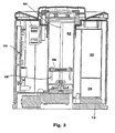
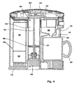
- the device shown in Figs. 1-4 comprises a housing 10, with a substantially cylindrical shape in the embodiment shown.
- the housing is arranged with a bottom plate 12, which may be arranged with fastening means (not shown) for attachment to the interior of a vehicle and a top lid 14 removably arranged.
- a control panel 15 is arranged on the housing, comprising buttons for choice of beverage, beverage strength and the like, and indication lamps for indicating the state of the device, such as warning for low powder or water level, that the device is operating and the like.
- the housing is further arranged with an opening 16 on the side, which opening opens up to a space 18 arranged for a mug or a cup 20 to be placed in.
- the space has an upper wall 22, Fig. 4, with a somewhat curved shape from the back wall 24 of the space to the upper edge of the opening.
- a mixing chamber 26 is arranged above the space with an outlet extending through the upper wall forming a tapping point 28.
- a supply means for water 30 is connected to the tapping point.
- the water supply means comprises a water tank 32 arranged inside the housing, containing an amount of water.
- the water tank is connected to an intermediate tank 34.
- the intermediate tank is adapted to contain a smaller, specific amount of water, e. g. for two mugs and is provided with heating means, not shown, for heating the water in the intermediate tank.
- the intermediate tank is connected to a pump (not shown), which in turn is connected to the tapping point 28 via a conduit.
- the device further comprises means for supplying powder for beverages 40, comprising a container 42 intended to contain powder for beverages, e. g. freeze-dried coffee powder.
- the container is arranged with an elongated vertical shape and rectangular cross-section.
- a threaded vertical shaft 44 is arranged in the container space.
- the bottom 46 of the container is arranged with a threaded through-hole, in which the shaft is arranged.
- the lower part of the shaft is supported by bearings and attached to an electrical motor 48, preferably a stepper motor, via a transmission.
- the bottom of the container is further provided with contact pins 49; which pins, when the bottom is at its lowermost position come in contact with breakers (not shown) for switching off the electrical motor.
- a measuring device (not shown) is arranged adjacent said transmission for measuring the position of the bottom in the container.
- the measuring device could comprise a light transmitter and receiver placed on opposite sides of wings connected to the shaft, where the wings have a certain space between each other.
- the transmitter will receive a light pulse every time a space is moved between the transmitter and the receiver, and by counting the pulses and knowing the number of pulses per revolution, and by knowing the thread pitch of the shaft, the exact position of the bottom may be obtained.
- the supply means further comprises a pusher device 50 arranged above the container.
- the pusher device comprises a slider tray 51, Figs. 5-8, comprising an opening 53 with a form, which fits onto the top end of the container 42.
- the slider tray further comprises a horizontal sliding surface 52 with an opening into the tubular part, and two guiding side walls 54.
- a recess 55 is arranged in one of the side-walls at the centre line of the opening as seen in a vertical direction.
- a longitudinal slot 57 is arranged along one of the side-walls.
- a pusher unit 59 is slidably arranged in the slider tray.
- the pusher unit comprises a toothed rack 56 is attached to the lower surface of the plate and protruding through the longitudinal slot.
- the rack is engaged with a cog-wheel rotatably attached to the shaft of an electrical motor (not shown).
- the pusher unit further comprises an opening 58 at its back end as seen in Fig. 5, which opening has substantially the same form and size as the opening in the slider tray.
- a compartment 60 is arranged, which is open downwards, where the opening of the compartment has substantially the same form and size as the opening of the slider tray.
- a plate 62 movably arranged to two downward directed guide pins 64.
- Each guide pin is arranged with a stop ledge or the like (not shown) for limiting the lowest position of the plate to when it is somewhat above the horizontal sliding surface.
- Each guide pin is further arranged with a compression spring 66 acting between the upper surface of the plate and the lower surface of the compartment, which springs urge the plate downwards.
- the compartment 60 is arranged with an opening on one sidewall. Inside the opening a protrusion 68 is arranged and attached to the upper surface of the plate. On the side surface of the protrusion facing the opening, a reflective layer is arranged. A sensor comprising a light transmitter and a light detector is arranged facing the recess and the opening.
- the pusher unit 59 is held in place on the tray 51 by a lid 70.
- the function of the device is as follows.
- the container 42 is filled from above with a powder for beverages, e. g. instant coffee by removing the top lid 14.
- the pusher unit 59 is positioned in its most advanced position whereby the opening 58 is placed above the container, and the bottom of the container is returned to its most down-ward position by rotating the threaded shaft 44.
- Powder may now be poured into the container 42.
- the lid is then brought back on, the slider motor is activated whereby its cog wheel acts on the rack and the pusher unit is withdrawn to its position where the compartment is above container. Thereafter the motor 48 rotating the shaft is activated so that the bottom 46 of the container is raised. This action pushes the powder upwards until it hits plate 62 of the compartment 60.
- the moving plate of the compartment and the detection means ensures that the compartment is always filled with powder as long as there is powder in the container.
- the filling is thus not dependent on the actual level of powder in the container, which level may vary due to different degrees of packing of the powder as the container is shaken.
- the position of the bottom kept updated by the measuring device and stored in a storage media for digital information.
- the water container 32 is filled with water whereby a certain amount enters the intermediate tank 34.
- the heating element in the intermediate tank heats the water.
- the device is activated, whereby the pump starts pumping heated water from the intermediate tank to the mixing chamber 26.
- the electrical motor operating the pusher unit is activated whereby its cog-wheel operates the rack 56 and thereby the pusher unit 59 so that it slides towards the mixing chamber.
- the plate slides forward the compartment is connected to the mixing chamber so that a metered amount of the powder contained by the compartment enters the mixing chamber and is mixed with the water.
- the force of the compression springs urges the plate to its lower position.
- the container In the forward position of the plate the container is protected by the pusher unit.
- the pusher unit is then quickly retracted by reversing the electrical motor whereby a sealing portion 72, Fig. 4, of the pusher unit seals off the connection between the mixing chamber 26 and the container 42. This because steam and moist otherwise could enter into the compartment and cause the powder to agglomerate.
- the motor operating the bottom 46 of the container is activated so that the powder is pushed upwards and into the compartment 60 until the powder has pushed the plate 62 so that the reflective surface is visible to the sensor, which leads to a shut-off of the motor and the angular position of the shaft is measured.
- the angular position in relation to the previous position enables a count of the number of metered amounts of powder delivered.
- the device preferably comprises electronic control means 74 including a printed circuit board, memory containing control program parts, relays timers, and micro processors for controlling and operating the device.
- the different motors, operation buttons, indication lamps, sensors, heating elements, pumps and the like are connected to the electronic control means for in and output of information and control signals.
- the control means could for example, apart from the above described functions, further automatically shut off the heater when the water level is low and automatically return the bottom of the container when all powder has been emptied. The return would also reset the stored position data for the bottom.
- the device may provide cold beverages as well, by e. g. pressing a certain button on the device.
- the water supply may be arranged with additional conduits between the water container and the pump so that cold water is pumped directly to the mixing chamber.
- the device may provide only hot water. Again, by pressing a certain button, hot water is pumped from the intermediate tank to the mixing chamber without activating the supply means.
- the device described above and shown on the drawings is designed as a separate unit.
- the device may however be integrated in for example the dashboard of a vehicle.
- the different components of the invention may be placed differently to each other in order to accommodate the device in the space available behind a dashboard.
Landscapes
- Engineering & Computer Science (AREA)
- Food Science & Technology (AREA)
- Apparatus For Making Beverages (AREA)
- Tea And Coffee (AREA)
- Non-Alcoholic Beverages (AREA)
- Beverage Vending Machines With Cups, And Gas Or Electricity Vending Machines (AREA)
Claims (11)
- Verfahren zum Zubereiten von Getränken, wobei Wasser aus einer Wasserquelle einer Entnahmestelle zugeleitet wird, wobei Getränkepulver von einem Behälter der Entnahmestelle zugeleitet wird, dadurch gekennzeichnet, dass das Zuleiten von Getränkepulver mit einem anderen Mittel als Gravitation erfolgt.
- Vorrichtung zum Zubereiten von Getränken mit einem Behälter (42) für Getränkepulver, einer Entnahmestelle (28), einem Mittel zum Zuleiten von Wasser (30) aus einer Wasserquelle (32) zur Entnahmestelle, einem Mittel zum Zuleiten von Getränkepulver (40) vom Behälter zur Entnahmestelle, dadurch gekennzeichnet, dass das Mittel zum Zuleiten von Getränkepulver derart gestaltet und eingerichtet ist, dass dieses das Getränkepulver mit einem anderen Mittel als Gravitation zuleitet.
- Vorrichtung nach Anspruch 2, dadurch gekennzeichnet, dass das Mittel zum Zuleiten von Getränkepulver ausgestattet ist mit einer mit dem Behälter und der Entnahmestelle in Verbindung stehenden Abteilung (62), einem zum Zuführen des Pulvers in die Abteilung eingerichteten Zuführmittel (44, 46) und einem zum Abdichten der Verbindung zwischen der Abteilung und der Entnahmestelle geeigneten Dichtmittel (72).
- Vorrichtung nach Anspruch 2, dadurch gekennzeichnet, dass das Mittel zum Zuleiten von Getränkepulver, wenn es aktiviert wird, eine dosierte Portion Getränkepulver zuleitet.
- Vorrichtung nach einem der vorhergehenden Ansprüche 2-4, gekennzeichnet durch ein Mittel zum Verändern der Größe des Behälters, wobei die Größe bei jedem Zuführen von Getränkepulver reduziert wird.
- Vorrichtung nach Anspruch 5, dadurch gekennzeichnet, dass die Größe entsprechend der dosierten Portion von Getränkepulver reduziert wird.
- Vorrichtung nach Anspruch 5 oder 6, dadurch gekennzeichnet, dass der Behälter eine verschiebbare Wand umfasst, welche dazu geeignet ist, das Pulver in die Abteilung zu schieben, wobei die Abteilung verschiebbar zwischen einer mit dem Behälter in Verbindung stehenden Position und einer mit der Entnahmestelle in Verbindung stehenden Position angeordnet ist.
- Vorrichtung nach Anspruch 7, dadurch gekennzeichnet, dass die Verbindung mit der Entnahmestelle abgedichtet ist, wenn die Abteilung mit dem Behälter in Verbindung steht, und dass der Behälter abgedichtet ist, wenn die Abteilung mit der Entnahmestelle in Verbindung steht.
- Vorrichtung nach einem der vorhergehenden Ansprüche 2-8, dadurch gekennzeichnet, dass die Abteilung mit einem Mittel ausgestattet ist, um festzustellen, wenn die Abteilung mit Pulver gefüllt ist.
- Vorrichtung nach Anspruch 2, dadurch gekennzeichnet, dass das Mittel zum Zuleiten von Wasser einen zwischen der Wasserquelle und der Entnahmestelle angeordneten Wassertank umfasst, und dass der dazwischen liegende Wassertank mit einem Heizmittel zum Aufheizen des im dazwischen liegenden Wassertank befindlichen Wassers versehen ist.
- Vorrichtung nach einem der vorgehenden Ansprüche 2-10, dadurch gekennzeichnet, dass die Entnahmestelle eine Mischkammer (26) zum Mischen des Pulvers und des Wassers umfasst.
Applications Claiming Priority (3)
| Application Number | Priority Date | Filing Date | Title |
|---|---|---|---|
| SE9904260A SE515236C2 (sv) | 1999-11-24 | 1999-11-24 | Metod och anordning för framställning av drycker |
| SE9904260 | 1999-11-24 | ||
| PCT/SE2000/002306 WO2001037714A1 (en) | 1999-11-24 | 2000-11-23 | Method and device for producing beverages |
Publications (2)
| Publication Number | Publication Date |
|---|---|
| EP1233692A1 EP1233692A1 (de) | 2002-08-28 |
| EP1233692B1 true EP1233692B1 (de) | 2004-09-01 |
Family
ID=20417844
Family Applications (1)
| Application Number | Title | Priority Date | Filing Date |
|---|---|---|---|
| EP00980196A Expired - Lifetime EP1233692B1 (de) | 1999-11-24 | 2000-11-23 | Verfahren und vorrichtung zum herstellen von getränken |
Country Status (8)
| Country | Link |
|---|---|
| US (1) | US7134384B1 (de) |
| EP (1) | EP1233692B1 (de) |
| AT (1) | ATE274830T1 (de) |
| AU (1) | AU1749101A (de) |
| DE (1) | DE60013474T2 (de) |
| ES (1) | ES2226953T3 (de) |
| SE (1) | SE515236C2 (de) |
| WO (1) | WO2001037714A1 (de) |
Cited By (1)
| Publication number | Priority date | Publication date | Assignee | Title |
|---|---|---|---|---|
| DE102005056425B4 (de) * | 2005-11-26 | 2012-06-14 | Audi Ag | Vorrichtung zur Erzeugung eines Getränks |
Families Citing this family (5)
| Publication number | Priority date | Publication date | Assignee | Title |
|---|---|---|---|---|
| ATE464818T1 (de) * | 2007-02-08 | 2010-05-15 | Wmf Wuerttemberg Metallwaren | Kaffeemaschine |
| CN103458746B (zh) * | 2010-11-12 | 2016-12-28 | 洛伦佐·贾科明 | 用于制备浓咖啡或泡制饮料的交流和/或低直流电压驱动的机器 |
| CN111297196B (zh) * | 2020-04-16 | 2026-03-17 | 杭州哇喔科技有限责任公司 | 防粉剂受潮结块的上出料推料机构 |
| CN111358297A (zh) * | 2020-04-16 | 2020-07-03 | 杭州哇喔科技有限责任公司 | 一种粉料出料机构 |
| IT202000025501A1 (it) * | 2020-10-27 | 2022-04-27 | Univ Degli Studi Genova | Dispositivo e metodo per reidratare polvere liofilizzata alimentare |
Family Cites Families (15)
| Publication number | Priority date | Publication date | Assignee | Title |
|---|---|---|---|---|
| US2935011A (en) * | 1958-06-10 | 1960-05-03 | Perlman Yaakov | Beverage-making machine |
| US3759162A (en) * | 1971-08-02 | 1973-09-18 | K Maxwell | Coffee maker for repetitively brewing single cups of fresh coffee |
| US3974758A (en) * | 1974-11-08 | 1976-08-17 | Stone Jr Wayne B | Apparatus for reducing oxidation of coffee |
| US4116246A (en) * | 1976-10-12 | 1978-09-26 | Medalie Manufacturing Co. | Beverage dispenser |
| ES235333Y (es) * | 1978-04-12 | 1978-11-01 | Nuevo aparato automatico para la preparacion de cafe ex- pres. | |
| US4300442A (en) * | 1980-04-28 | 1981-11-17 | Societe D'assistance Technique Pour Produits Nestle Sa | Coffee maker |
| DK164308C (da) * | 1984-08-03 | 1992-10-19 | Wittenborgs Automatfab | Automat til udlevering af baegre med friskbryggede drikkevarer |
| AU567197B2 (en) * | 1984-11-29 | 1987-11-12 | Douwe Egberts Koninklijke Tabaksfabriek-Koffiebranderijen-Theehandel N.V. | Coffee maker |
| FR2579881B1 (de) * | 1985-04-03 | 1988-07-15 | Seb Sa | |
| CH685668A5 (de) * | 1993-08-11 | 1995-09-15 | Prodiana Ag | Kaffeemaschine mit Dosiervorrichtung. |
| US5367948A (en) * | 1994-03-14 | 1994-11-29 | Judith Di Fusco | Quantity measuring coffee machine |
| CH689754A5 (it) * | 1995-07-31 | 1999-10-15 | Lough J Ltd | Macchina per la realizzazione di bevande del tipo caffè espresso con introduzione automatica della polvere di caffè ed espulsione dei fondi. |
| JPH09327389A (ja) * | 1996-06-11 | 1997-12-22 | Sanden Corp | コーヒー抽出装置及びコーヒー抽出方法 |
| US5823096A (en) * | 1997-10-14 | 1998-10-20 | Shih; Chun-Hong | Automatic infusing apparatus |
| US6360650B1 (en) * | 2000-07-03 | 2002-03-26 | Joseph Mangiapane | Multiple beverage preparation device |
-
1999
- 1999-11-24 SE SE9904260A patent/SE515236C2/sv not_active IP Right Cessation
-
2000
- 2000-11-23 WO PCT/SE2000/002306 patent/WO2001037714A1/en not_active Ceased
- 2000-11-23 US US10/130,980 patent/US7134384B1/en not_active Expired - Fee Related
- 2000-11-23 ES ES00980196T patent/ES2226953T3/es not_active Expired - Lifetime
- 2000-11-23 AU AU17491/01A patent/AU1749101A/en not_active Abandoned
- 2000-11-23 AT AT00980196T patent/ATE274830T1/de not_active IP Right Cessation
- 2000-11-23 EP EP00980196A patent/EP1233692B1/de not_active Expired - Lifetime
- 2000-11-23 DE DE60013474T patent/DE60013474T2/de not_active Expired - Fee Related
Cited By (1)
| Publication number | Priority date | Publication date | Assignee | Title |
|---|---|---|---|---|
| DE102005056425B4 (de) * | 2005-11-26 | 2012-06-14 | Audi Ag | Vorrichtung zur Erzeugung eines Getränks |
Also Published As
| Publication number | Publication date |
|---|---|
| ATE274830T1 (de) | 2004-09-15 |
| AU1749101A (en) | 2001-06-04 |
| EP1233692A1 (de) | 2002-08-28 |
| SE515236C2 (sv) | 2001-07-02 |
| SE9904260D0 (sv) | 1999-11-24 |
| SE9904260L (sv) | 2001-05-25 |
| ES2226953T3 (es) | 2005-04-01 |
| DE60013474T2 (de) | 2005-08-18 |
| DE60013474D1 (de) | 2004-10-07 |
| US7134384B1 (en) | 2006-11-14 |
| WO2001037714A1 (en) | 2001-05-31 |
Similar Documents
| Publication | Publication Date | Title |
|---|---|---|
| TWI498092B (zh) | 藉著自動供水至加熱器槽之飲料形成方法及裝置 | |
| RU2538539C2 (ru) | Система для приготовления кофейного напитка | |
| US3596588A (en) | Automatic beverage maker | |
| US6164191A (en) | Single serving beverage maker | |
| US6173117B1 (en) | Heated beverage machine | |
| US8863987B2 (en) | Beverage apparatus waste bin level detection | |
| US4531658A (en) | Measured charge dispenser, particularly for powdered material | |
| EP2123201B1 (de) | Automatischer Getränkespender mit verbesserter Abgabevorrichtung | |
| EP1768529B1 (de) | Für den einsatz in flugzeugen geeignete kaffeemaschine | |
| JP2013544173A (ja) | 信頼性の高いユーザーインジケータ付き飲料機 | |
| US7134384B1 (en) | Method and device for producing beverages | |
| CN105321263A (zh) | 杯内饮料调制方法 | |
| KR20160107300A (ko) | 음료 병 검출을 위한 방법 및 장치 | |
| EP2447644A2 (de) | Getränkeherstellender Einsatz mit eingebauter Wasserleitung | |
| US6948421B2 (en) | Brewing apparatus | |
| EP1254621B1 (de) | Zuckerspendersystem in einem Verkaufsautomat für Heissgetränke | |
| US3045719A (en) | Dispenser apparatus | |
| KR20240121172A (ko) | 음료/슬러시를 토출하기 위한 토출 장치 및 음료/슬러시의 토출 방법 | |
| GB2041881A (en) | Drink dispenser | |
| CN112244671B (zh) | 一种混合饮料自动调配装置 | |
| JP3593933B2 (ja) | カップ式自動販売機 | |
| KR0131884Y1 (ko) | 커피 냉장고 시스템의 커피 기능록 장치 | |
| JP3593930B2 (ja) | カップ式自動販売機 | |
| RU2336223C2 (ru) | Устройство для выдачи напитка из жидкого концентрата/экстракта со сменным картриджем с концентратом/экстрактом | |
| JP2001023036A (ja) | カップ式自動販売機 |
Legal Events
| Date | Code | Title | Description |
|---|---|---|---|
| PUAI | Public reference made under article 153(3) epc to a published international application that has entered the european phase |
Free format text: ORIGINAL CODE: 0009012 |
|
| 17P | Request for examination filed |
Effective date: 20020611 |
|
| AK | Designated contracting states |
Kind code of ref document: A1 Designated state(s): AT BE CH CY DE DK ES FI FR GB GR IE IT LI LU MC NL PT SE TR |
|
| AX | Request for extension of the european patent |
Free format text: AL;LT;LV;MK;RO;SI |
|
| GRAP | Despatch of communication of intention to grant a patent |
Free format text: ORIGINAL CODE: EPIDOSNIGR1 |
|
| GRAS | Grant fee paid |
Free format text: ORIGINAL CODE: EPIDOSNIGR3 |
|
| GRAA | (expected) grant |
Free format text: ORIGINAL CODE: 0009210 |
|
| AK | Designated contracting states |
Kind code of ref document: B1 Designated state(s): AT BE CH CY DE DK ES FI FR GB GR IE IT LI LU MC NL PT SE TR |
|
| PG25 | Lapsed in a contracting state [announced via postgrant information from national office to epo] |
Ref country code: CH Free format text: LAPSE BECAUSE OF FAILURE TO SUBMIT A TRANSLATION OF THE DESCRIPTION OR TO PAY THE FEE WITHIN THE PRESCRIBED TIME-LIMIT Effective date: 20040901 Ref country code: FI Free format text: LAPSE BECAUSE OF FAILURE TO SUBMIT A TRANSLATION OF THE DESCRIPTION OR TO PAY THE FEE WITHIN THE PRESCRIBED TIME-LIMIT Effective date: 20040901 Ref country code: BE Free format text: LAPSE BECAUSE OF FAILURE TO SUBMIT A TRANSLATION OF THE DESCRIPTION OR TO PAY THE FEE WITHIN THE PRESCRIBED TIME-LIMIT Effective date: 20040901 Ref country code: LI Free format text: LAPSE BECAUSE OF FAILURE TO SUBMIT A TRANSLATION OF THE DESCRIPTION OR TO PAY THE FEE WITHIN THE PRESCRIBED TIME-LIMIT Effective date: 20040901 Ref country code: CY Free format text: LAPSE BECAUSE OF FAILURE TO SUBMIT A TRANSLATION OF THE DESCRIPTION OR TO PAY THE FEE WITHIN THE PRESCRIBED TIME-LIMIT Effective date: 20040901 Ref country code: TR Free format text: LAPSE BECAUSE OF FAILURE TO SUBMIT A TRANSLATION OF THE DESCRIPTION OR TO PAY THE FEE WITHIN THE PRESCRIBED TIME-LIMIT Effective date: 20040901 Ref country code: AT Free format text: LAPSE BECAUSE OF FAILURE TO SUBMIT A TRANSLATION OF THE DESCRIPTION OR TO PAY THE FEE WITHIN THE PRESCRIBED TIME-LIMIT Effective date: 20040901 |
|
| REG | Reference to a national code |
Ref country code: GB Ref legal event code: FG4D |
|
| REG | Reference to a national code |
Ref country code: CH Ref legal event code: EP |
|
| REG | Reference to a national code |
Ref country code: IE Ref legal event code: FG4D |
|
| REF | Corresponds to: |
Ref document number: 60013474 Country of ref document: DE Date of ref document: 20041007 Kind code of ref document: P |
|
| PG25 | Lapsed in a contracting state [announced via postgrant information from national office to epo] |
Ref country code: LU Free format text: LAPSE BECAUSE OF NON-PAYMENT OF DUE FEES Effective date: 20041123 Ref country code: IE Free format text: LAPSE BECAUSE OF NON-PAYMENT OF DUE FEES Effective date: 20041123 |
|
| PG25 | Lapsed in a contracting state [announced via postgrant information from national office to epo] |
Ref country code: MC Free format text: LAPSE BECAUSE OF NON-PAYMENT OF DUE FEES Effective date: 20041130 |
|
| PG25 | Lapsed in a contracting state [announced via postgrant information from national office to epo] |
Ref country code: DK Free format text: LAPSE BECAUSE OF FAILURE TO SUBMIT A TRANSLATION OF THE DESCRIPTION OR TO PAY THE FEE WITHIN THE PRESCRIBED TIME-LIMIT Effective date: 20041201 Ref country code: GR Free format text: LAPSE BECAUSE OF FAILURE TO SUBMIT A TRANSLATION OF THE DESCRIPTION OR TO PAY THE FEE WITHIN THE PRESCRIBED TIME-LIMIT Effective date: 20041201 Ref country code: SE Free format text: LAPSE BECAUSE OF FAILURE TO SUBMIT A TRANSLATION OF THE DESCRIPTION OR TO PAY THE FEE WITHIN THE PRESCRIBED TIME-LIMIT Effective date: 20041201 |
|
| LTIE | Lt: invalidation of european patent or patent extension |
Effective date: 20040901 |
|
| REG | Reference to a national code |
Ref country code: CH Ref legal event code: PL |
|
| REG | Reference to a national code |
Ref country code: ES Ref legal event code: FG2A Ref document number: 2226953 Country of ref document: ES Kind code of ref document: T3 |
|
| PLBE | No opposition filed within time limit |
Free format text: ORIGINAL CODE: 0009261 |
|
| STAA | Information on the status of an ep patent application or granted ep patent |
Free format text: STATUS: NO OPPOSITION FILED WITHIN TIME LIMIT |
|
| ET | Fr: translation filed | ||
| 26N | No opposition filed |
Effective date: 20050602 |
|
| REG | Reference to a national code |
Ref country code: IE Ref legal event code: MM4A |
|
| PGFP | Annual fee paid to national office [announced via postgrant information from national office to epo] |
Ref country code: FR Payment date: 20061031 Year of fee payment: 7 |
|
| PGFP | Annual fee paid to national office [announced via postgrant information from national office to epo] |
Ref country code: NL Payment date: 20061109 Year of fee payment: 7 |
|
| PGFP | Annual fee paid to national office [announced via postgrant information from national office to epo] |
Ref country code: GB Payment date: 20061121 Year of fee payment: 7 |
|
| PGFP | Annual fee paid to national office [announced via postgrant information from national office to epo] |
Ref country code: DE Payment date: 20061124 Year of fee payment: 7 Ref country code: ES Payment date: 20061124 Year of fee payment: 7 |
|
| PG25 | Lapsed in a contracting state [announced via postgrant information from national office to epo] |
Ref country code: PT Free format text: LAPSE BECAUSE OF NON-PAYMENT OF DUE FEES Effective date: 20050201 |
|
| PGFP | Annual fee paid to national office [announced via postgrant information from national office to epo] |
Ref country code: IT Payment date: 20071121 Year of fee payment: 8 |
|
| GBPC | Gb: european patent ceased through non-payment of renewal fee |
Effective date: 20071123 |
|
| NLV4 | Nl: lapsed or anulled due to non-payment of the annual fee |
Effective date: 20080601 |
|
| PG25 | Lapsed in a contracting state [announced via postgrant information from national office to epo] |
Ref country code: NL Free format text: LAPSE BECAUSE OF NON-PAYMENT OF DUE FEES Effective date: 20080601 Ref country code: DE Free format text: LAPSE BECAUSE OF NON-PAYMENT OF DUE FEES Effective date: 20080603 |
|
| REG | Reference to a national code |
Ref country code: FR Ref legal event code: ST Effective date: 20080930 |
|
| PG25 | Lapsed in a contracting state [announced via postgrant information from national office to epo] |
Ref country code: GB Free format text: LAPSE BECAUSE OF NON-PAYMENT OF DUE FEES Effective date: 20071123 |
|
| REG | Reference to a national code |
Ref country code: ES Ref legal event code: FD2A Effective date: 20071124 |
|
| PG25 | Lapsed in a contracting state [announced via postgrant information from national office to epo] |
Ref country code: FR Free format text: LAPSE BECAUSE OF NON-PAYMENT OF DUE FEES Effective date: 20071130 Ref country code: ES Free format text: LAPSE BECAUSE OF NON-PAYMENT OF DUE FEES Effective date: 20071124 |
|
| PG25 | Lapsed in a contracting state [announced via postgrant information from national office to epo] |
Ref country code: IT Free format text: LAPSE BECAUSE OF NON-PAYMENT OF DUE FEES Effective date: 20081123 |