EP1233643A2 - Microphone miniature avec protection améliorée contre le vent - Google Patents
Microphone miniature avec protection améliorée contre le vent Download PDFInfo
- Publication number
- EP1233643A2 EP1233643A2 EP02450003A EP02450003A EP1233643A2 EP 1233643 A2 EP1233643 A2 EP 1233643A2 EP 02450003 A EP02450003 A EP 02450003A EP 02450003 A EP02450003 A EP 02450003A EP 1233643 A2 EP1233643 A2 EP 1233643A2
- Authority
- EP
- European Patent Office
- Prior art keywords
- microphone
- volume
- capsule
- housing
- inlet openings
- Prior art date
- Legal status (The legal status is an assumption and is not a legal conclusion. Google has not performed a legal analysis and makes no representation as to the accuracy of the status listed.)
- Withdrawn
Links
- 239000002775 capsule Substances 0.000 claims abstract description 44
- 239000006260 foam Substances 0.000 claims description 17
- 239000013598 vector Substances 0.000 description 10
- 230000035945 sensitivity Effects 0.000 description 7
- 239000012528 membrane Substances 0.000 description 5
- 238000013016 damping Methods 0.000 description 3
- 238000010586 diagram Methods 0.000 description 3
- 230000001681 protective effect Effects 0.000 description 3
- 230000001419 dependent effect Effects 0.000 description 2
- 239000011148 porous material Substances 0.000 description 2
- 230000032683 aging Effects 0.000 description 1
- 230000001914 calming effect Effects 0.000 description 1
- 238000010276 construction Methods 0.000 description 1
- 230000008878 coupling Effects 0.000 description 1
- 238000010168 coupling process Methods 0.000 description 1
- 238000005859 coupling reaction Methods 0.000 description 1
- 239000000428 dust Substances 0.000 description 1
- 230000000694 effects Effects 0.000 description 1
- 239000013013 elastic material Substances 0.000 description 1
- 230000007613 environmental effect Effects 0.000 description 1
- 239000002360 explosive Substances 0.000 description 1
- 239000003292 glue Substances 0.000 description 1
- 230000010354 integration Effects 0.000 description 1
- 210000003734 kidney Anatomy 0.000 description 1
- 238000004519 manufacturing process Methods 0.000 description 1
- 238000000034 method Methods 0.000 description 1
- 238000007493 shaping process Methods 0.000 description 1
- 230000003068 static effect Effects 0.000 description 1
Images

Classifications
-
- H—ELECTRICITY
- H04—ELECTRIC COMMUNICATION TECHNIQUE
- H04R—LOUDSPEAKERS, MICROPHONES, GRAMOPHONE PICK-UPS OR LIKE ACOUSTIC ELECTROMECHANICAL TRANSDUCERS; DEAF-AID SETS; PUBLIC ADDRESS SYSTEMS
- H04R1/00—Details of transducers, loudspeakers or microphones
- H04R1/08—Mouthpieces; Microphones; Attachments therefor
- H04R1/083—Special constructions of mouthpieces
- H04R1/086—Protective screens, e.g. all weather or wind screens
-
- H—ELECTRICITY
- H04—ELECTRIC COMMUNICATION TECHNIQUE
- H04R—LOUDSPEAKERS, MICROPHONES, GRAMOPHONE PICK-UPS OR LIKE ACOUSTIC ELECTROMECHANICAL TRANSDUCERS; DEAF-AID SETS; PUBLIC ADDRESS SYSTEMS
- H04R1/00—Details of transducers, loudspeakers or microphones
- H04R1/20—Arrangements for obtaining desired frequency or directional characteristics
- H04R1/32—Arrangements for obtaining desired frequency or directional characteristics for obtaining desired directional characteristic only
- H04R1/34—Arrangements for obtaining desired frequency or directional characteristics for obtaining desired directional characteristic only by using a single transducer with sound reflecting, diffracting, directing or guiding means
- H04R1/38—Arrangements for obtaining desired frequency or directional characteristics for obtaining desired directional characteristic only by using a single transducer with sound reflecting, diffracting, directing or guiding means in which sound waves act upon both sides of a diaphragm and incorporating acoustic phase-shifting means, e.g. pressure-gradient microphone
-
- H—ELECTRICITY
- H04—ELECTRIC COMMUNICATION TECHNIQUE
- H04R—LOUDSPEAKERS, MICROPHONES, GRAMOPHONE PICK-UPS OR LIKE ACOUSTIC ELECTROMECHANICAL TRANSDUCERS; DEAF-AID SETS; PUBLIC ADDRESS SYSTEMS
- H04R2410/00—Microphones
- H04R2410/07—Mechanical or electrical reduction of wind noise generated by wind passing a microphone
Definitions
- the present invention relates to a miniature microphone with a in a microphone housing housed microphone capsule with front sound inlets leading to one front volume, with rear sound inlet openings leading to a rear Lead volume and with a connection volume, thus a pressure gradient receiver, with improved wind protection or pop protection.
- Microphone capsules regardless of their physical mode of operation, can act as pressure receivers or built up as a pressure gradient receiver.
- the two capsule types differ from each other mainly in the directivity that can be achieved.
- the directional characteristic of a microphone capsule is dependent on the sensitivity of the capsule defined by the angle of objection, and can be considered a spherical, kidney, hypemic, Supercardioid or figure-eight polar pattern with associated polar diagram to be discribed.
- pressure gradient receivers In order to achieve a one-sided directional characteristic, so-called pressure gradient receivers must be used be built. They not only have a front sound inlet opening, but also a second one, which can be realized either on the side or at the back with whose help the membrane of the microphone capsule is exposed to a pressure difference.
- the Acoustic tuning of a pressure gradient capsule is carried out by a specialist known acoustic means, so that both the desired directional characteristic, as well as a desired frequency response is achieved.
- the microphone capsules have a pronounced one-sided directional characteristic because of their noise-reducing properties are required, they have compared to capsules spherical polar pattern also has a major disadvantage compared to wind or so-called pop noises. Pop noises arise when inexperienced pronunciation of Explosive consonants like "P" or "B".
- the damping of the wind noise takes place according to the known prior art with the help of different types of microphone baskets.
- the microphone baskets which also serve as mechanical protection of the microphone capsule, with various porous materials filled. This is mainly done using open-cell foams, which either inserted into the inside of the microphone grille basket or as a wind protection cap on the Microphone grill cap are placed.
- the effectiveness of such wind protection devices is on the one hand from the foam density and on the other hand from the distance to the microphone capsule dependent.
- a denser foam generally provides better wind protection, however also a loss of sensitivity of the microphone at higher frequencies. Behaves similarly the distance from the microphone capsule to be protected. A bigger one Distance means better protection, but with the disadvantage that the microphone can no longer be kept inconspicuously small.
- Miniature microphones which are mainly on the human body, either through Buckle up, clip on, stick on or put on are used for the purpose of Reduction of wind or pop sensitivity executed as a pressure receiver.
- the wind sensitivity of the microphone can be kept low, but on the other hand are also undesirable due to the spherical polar pattern of the microphone Receive and transmit noise from the acoustic environment of the microphone.
- the use of miniature microphones with one-sided directional characteristic was until now particularly difficult due to their sensitivity to wind. They absolutely had to Wear an outer protective cap made of foam.
- the aim of the invention is the integration of miniature microphones, which are made from dynamic or electret capsules with one-sided directional characteristic in components with low Dimensions (e.g. microphone arm of a headset) with the special feature of an integrated To allow wind protection without the structure of the microphone complicated and expensive shape.
- these objectives are achieved in that, in the installed state Microphone capsule with the help of narrow channels, which are inside the microphone housing be carried out, an acoustic connection between the front and rear side the microphone capsule is realized.
- Fig. 2 is a diagram for explaining the problem underlying the invention
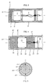
- 3 shows a small microphone according to the prior art
- 4 shows a cross section through an inventive microphone
- 5 shows a section along the line VV of FIG. 4th
- Fig. 1 shows, shown by the wavy lines, a turbulent Sound field in which there is a microphone capsule with two sound inlet openings a and b located.
- P0 is the static air pressure, the intensity changes of which are so slow that they can be neglected.
- Two vectors Pa and Pb are shown on the tip of the vector P0.
- the diaphragm driving force at one Pressure gradient capsule can be much larger than a pressure capsule. And This is because in a turbulent air pressure field, the pressure differences between two neighboring points can become significantly larger than the air pressure at one Point in the same turbulent air pressure field over time, as can be seen from Fig. 2.
- the microphones that are built with such microphone capsules are special is sensitive to wind noise and its damping is usually only with realizable with great effort.
- the pressure gradient receiver executed microphone capsule 1 two (not shown separately) sound inlet openings has that but in the rear volume 7 with the rear sound entry openings 3 no Foam is inserted and that the capsule holder 2 the front volume of rear volume (acoustically) completely isolated. So you save a lot of manufacturing costs, but increases the wind sensitivity of the microphone, because only completely identical sound paths do not lead to any additional pressure differences on the membrane of the capsule.
- FIGS. 4 and 5 A solution according to the invention is shown in FIGS. 4 and 5: a conventional pressure gradient capsule 11 with one-sided directional characteristic is usually in one cylindrical housing 12, which can also be designed with a different shape, and is held by knobs or webs 13 which protrude inwards from the housing wall.
- a conventional pressure gradient capsule 11 with one-sided directional characteristic is usually in one cylindrical housing 12, which can also be designed with a different shape, and is held by knobs or webs 13 which protrude inwards from the housing wall.
- front sound inlet openings 14 and rear sound inlet openings 15 provided in the housing 12 is a front through the inserted capsule 11 Volume 16, a rear volume 17 and a connecting volume connecting the two 18 trained.
- the front volume 16 and the rear volume 17 are each with at least one sound-permeable foam part 19 completely or partially filled.
- the connection volume 18 acts as a calming zone and results in connection with the properties of the foam 19 a very strong damping of wind noise.
- the front sound inlet openings 14 allow the sound to enter the front from the front Volume 16, so that both to the inlet openings (not shown separately) on the Front of the capsule 11 and, by means of the connection volume 18, to the rear Volume 17 and from there to the rear sound inlet openings (not shown separately) on the back of the capsule 11.
- the rear wall of the rear volume 17 is acoustic from the following building structure tightly insulated, in that firstly the volume 17 is kept small and secondly that the microphone housing 12 is closed on the inside and no coupling to other volumes allows. 4, the connecting wires 10 of the microphone capsule 11 can still be seen. They are pulled through an opening and the opening is closed with the help of glue or other elastic material 21 closed, so that the remaining volume 20 of the microphone housing is not acoustically coupled to the volume 17.
- the size of the volumes and the inlet openings is determined using the microphone construction Usually used criteria selected so that the desired shaping of the Frequency response is reached.
- the shape and size of the front volume 16, which is preferred is completely filled with foam 19, is preferably chosen so that its Height (distance between the front of the microphone capsule 11 and the front Sound inlet openings 14) about 1 ⁇ 4 of the smallest wavelength to be transmitted (highest frequency to be transmitted). In this way, one exploits its effect as a resonator and widens the microphone frequency curve at higher frequencies.
- the size of the rear Volume 17 is less critical as long as the openings 15 are close enough to the first Bottom of the capsule 11 are arranged and secondly, their size an uninhibited Allows passage of sound.
- the connection channels, shown as connection volume 18 are preferably about 0.5 to 2 mm wide (radial extension). You can be trained even broader, but this only makes sense in exceptional cases because the microphone gets bigger again.
- volume an empty or with foam or the like. partially or completely filled volume is understood, but at least acoustically essentially is permeable.
Landscapes
- Health & Medical Sciences (AREA)
- Otolaryngology (AREA)
- Physics & Mathematics (AREA)
- Engineering & Computer Science (AREA)
- Acoustics & Sound (AREA)
- Signal Processing (AREA)
- Details Of Audible-Bandwidth Transducers (AREA)
- Obtaining Desirable Characteristics In Audible-Bandwidth Transducers (AREA)
Applications Claiming Priority (2)
| Application Number | Priority Date | Filing Date | Title |
|---|---|---|---|
| AT2402001A AT411560B (de) | 2001-02-15 | 2001-02-15 | Miniaturmikrofon mit integriertem windschutz |
| AT2402001 | 2001-02-15 |
Publications (2)
| Publication Number | Publication Date |
|---|---|
| EP1233643A2 true EP1233643A2 (fr) | 2002-08-21 |
| EP1233643A3 EP1233643A3 (fr) | 2004-01-21 |
Family
ID=3670045
Family Applications (1)
| Application Number | Title | Priority Date | Filing Date |
|---|---|---|---|
| EP02450003A Withdrawn EP1233643A3 (fr) | 2001-02-15 | 2002-01-10 | Microphone miniature avec protection améliorée contre le vent |
Country Status (5)
| Country | Link |
|---|---|
| EP (1) | EP1233643A3 (fr) |
| JP (1) | JP3819305B2 (fr) |
| CN (1) | CN100508646C (fr) |
| AT (1) | AT411560B (fr) |
| AU (1) | AU784595B2 (fr) |
Cited By (2)
| Publication number | Priority date | Publication date | Assignee | Title |
|---|---|---|---|---|
| DE102006001350A1 (de) * | 2006-01-09 | 2007-07-12 | Sennheiser Electronic Gmbh & Co. Kg | Mikrofon |
| US11051094B2 (en) | 2019-10-25 | 2021-06-29 | Shore Acquisition Holdings, Inc. | Interchangeable port acoustical cap for microphones |
Families Citing this family (1)
| Publication number | Priority date | Publication date | Assignee | Title |
|---|---|---|---|---|
| JP5838058B2 (ja) * | 2011-08-24 | 2015-12-24 | 株式会社オーディオテクニカ | 単一指向性マイクロホン |
Family Cites Families (4)
| Publication number | Priority date | Publication date | Assignee | Title |
|---|---|---|---|---|
| US5204907A (en) * | 1991-05-28 | 1993-04-20 | Motorola, Inc. | Noise cancelling microphone and boot mounting arrangement |
| US5329593A (en) * | 1993-05-10 | 1994-07-12 | Lazzeroni John J | Noise cancelling microphone |
| US5781643A (en) * | 1996-08-16 | 1998-07-14 | Shure Brothers Incorporated | Microphone plosive effects reduction techniques |
| CN1095622C (zh) * | 1996-10-11 | 2002-12-04 | 张炳林 | 一种防疫消毒电话筒 |
-
2001
- 2001-02-15 AT AT2402001A patent/AT411560B/de not_active IP Right Cessation
-
2002
- 2002-01-10 EP EP02450003A patent/EP1233643A3/fr not_active Withdrawn
- 2002-02-06 AU AU15449/02A patent/AU784595B2/en not_active Ceased
- 2002-02-07 CN CNB021035652A patent/CN100508646C/zh not_active Expired - Lifetime
- 2002-02-14 JP JP2002036788A patent/JP3819305B2/ja not_active Expired - Lifetime
Cited By (3)
| Publication number | Priority date | Publication date | Assignee | Title |
|---|---|---|---|---|
| DE102006001350A1 (de) * | 2006-01-09 | 2007-07-12 | Sennheiser Electronic Gmbh & Co. Kg | Mikrofon |
| DE102006001350B4 (de) * | 2006-01-09 | 2010-10-28 | Sennheiser Electronic Gmbh & Co. Kg | Mikrofon und Modifikationseinheit zum Modifizieren der akustischen Eigenschaften eines Mikrofons |
| US11051094B2 (en) | 2019-10-25 | 2021-06-29 | Shore Acquisition Holdings, Inc. | Interchangeable port acoustical cap for microphones |
Also Published As
| Publication number | Publication date |
|---|---|
| JP3819305B2 (ja) | 2006-09-06 |
| EP1233643A3 (fr) | 2004-01-21 |
| CN1371233A (zh) | 2002-09-25 |
| JP2002262380A (ja) | 2002-09-13 |
| ATA2402001A (de) | 2003-07-15 |
| AT411560B (de) | 2004-02-25 |
| AU1544902A (en) | 2002-08-22 |
| CN100508646C (zh) | 2009-07-01 |
| AU784595B2 (en) | 2006-05-11 |
Similar Documents
| Publication | Publication Date | Title |
|---|---|---|
| DE60005382T2 (de) | Breitbandiger unterwasser-schallwandler | |
| DE112012003442T5 (de) | Akustische Vorrichtung und Herstellungsverfahren | |
| DE2742600C2 (fr) | ||
| CH671665A5 (fr) | ||
| DE19706074C1 (de) | Richtmikrofon, insbesondere mit symmetrischer Richtwirkung | |
| WO2009033565A1 (fr) | Bouchon d'oreille | |
| EP1351549A2 (fr) | Capsule microphonique à gradient de pression | |
| DE3010313C2 (de) | Richtmikrophon | |
| DE202017107455U1 (de) | Lautsprecherhülle für ein mobiles Gerät sowie Lautsprechersystem mit einer solchen Lautsprecherhülle | |
| EP0493361B1 (fr) | Combiné téléphonique muni d'un microphone directionnel | |
| AT411560B (de) | Miniaturmikrofon mit integriertem windschutz | |
| DE2509369A1 (de) | Offenes lautsprecher-gehaeuse | |
| DE69613706T2 (de) | Montageanordnung eines geräuschunterdrückenden mikrofons | |
| DE3835384C2 (fr) | ||
| DE202020106027U1 (de) | Windschutz für ein Mikrofon | |
| DE4119615C2 (de) | Gehörschützender Ohrpfropfen | |
| DE112006002866T5 (de) | Lärmauslöschungskopfhörer | |
| WO2012022382A1 (fr) | Dispositif de protection pour microphone | |
| DE10258183B3 (de) | Slider-Mobiltelefon mit Biegewellenlautsprecher | |
| DE965801C (de) | Schalldaempfer | |
| CH479928A (de) | Mikrophon für Musikinstrumente | |
| DE1762237C3 (de) | Lautsprecheranlage, insbesondere für die Niederfrequenz-Tonwiedergabe | |
| WO1999014981A1 (fr) | Microphone | |
| DE102010019633A1 (de) | Hörermodul | |
| AT217523B (de) | Vorrichtung zum Aufnehmen oder Wiedergeben akustischer Schwingungen mit einer veränderlichen akustischen Impedanz |
Legal Events
| Date | Code | Title | Description |
|---|---|---|---|
| PUAI | Public reference made under article 153(3) epc to a published international application that has entered the european phase |
Free format text: ORIGINAL CODE: 0009012 |
|
| AK | Designated contracting states |
Kind code of ref document: A2 Designated state(s): AT BE CH CY DE DK ES FI FR GB GR IE IT LI LU MC NL PT SE TR |
|
| AX | Request for extension of the european patent |
Free format text: AL;LT;LV;MK;RO;SI |
|
| PUAL | Search report despatched |
Free format text: ORIGINAL CODE: 0009013 |
|
| AK | Designated contracting states |
Kind code of ref document: A3 Designated state(s): AT BE CH CY DE DK ES FI FR GB GR IE IT LI LU MC NL PT SE TR |
|
| AX | Request for extension of the european patent |
Extension state: AL LT LV MK RO SI |
|
| 17P | Request for examination filed |
Effective date: 20040721 |
|
| 17Q | First examination report despatched |
Effective date: 20040812 |
|
| AKX | Designation fees paid |
Designated state(s): AT BE CH CY DE DK ES FI FR GB GR IE IT LI LU MC NL PT SE TR |
|
| STAA | Information on the status of an ep patent application or granted ep patent |
Free format text: STATUS: THE APPLICATION IS DEEMED TO BE WITHDRAWN |
|
| 18D | Application deemed to be withdrawn |
Effective date: 20091006 |