EP1233322A2 - Pedal - Google Patents
Pedal Download PDFInfo
- Publication number
- EP1233322A2 EP1233322A2 EP02003498A EP02003498A EP1233322A2 EP 1233322 A2 EP1233322 A2 EP 1233322A2 EP 02003498 A EP02003498 A EP 02003498A EP 02003498 A EP02003498 A EP 02003498A EP 1233322 A2 EP1233322 A2 EP 1233322A2
- Authority
- EP
- European Patent Office
- Prior art keywords
- pedal
- lever
- arm
- pedal arm
- stop
- Prior art date
- Legal status (The legal status is an assumption and is not a legal conclusion. Google has not performed a legal analysis and makes no representation as to the accuracy of the status listed.)
- Granted
Links
Images


Classifications
-
- G—PHYSICS
- G05—CONTROLLING; REGULATING
- G05G—CONTROL DEVICES OR SYSTEMS INSOFAR AS CHARACTERISED BY MECHANICAL FEATURES ONLY
- G05G1/00—Controlling members, e.g. knobs or handles; Assemblies or arrangements thereof; Indicating position of controlling members
- G05G1/30—Controlling members actuated by foot
-
- B—PERFORMING OPERATIONS; TRANSPORTING
- B60—VEHICLES IN GENERAL
- B60K—ARRANGEMENT OR MOUNTING OF PROPULSION UNITS OR OF TRANSMISSIONS IN VEHICLES; ARRANGEMENT OR MOUNTING OF PLURAL DIVERSE PRIME-MOVERS IN VEHICLES; AUXILIARY DRIVES FOR VEHICLES; INSTRUMENTATION OR DASHBOARDS FOR VEHICLES; ARRANGEMENTS IN CONNECTION WITH COOLING, AIR INTAKE, GAS EXHAUST OR FUEL SUPPLY OF PROPULSION UNITS IN VEHICLES
- B60K26/00—Arrangement or mounting of propulsion-unit control devices in vehicles
- B60K26/02—Arrangement or mounting of propulsion-unit control devices in vehicles of initiating means or elements
-
- B—PERFORMING OPERATIONS; TRANSPORTING
- B60—VEHICLES IN GENERAL
- B60T—VEHICLE BRAKE CONTROL SYSTEMS OR PARTS THEREOF; BRAKE CONTROL SYSTEMS OR PARTS THEREOF, IN GENERAL; ARRANGEMENT OF BRAKING ELEMENTS ON VEHICLES IN GENERAL; PORTABLE DEVICES FOR PREVENTING UNWANTED MOVEMENT OF VEHICLES; VEHICLE MODIFICATIONS TO FACILITATE COOLING OF BRAKES
- B60T7/00—Brake-action initiating means
- B60T7/02—Brake-action initiating means for personal initiation
- B60T7/04—Brake-action initiating means for personal initiation foot actuated
- B60T7/06—Disposition of pedal
-
- G—PHYSICS
- G05—CONTROLLING; REGULATING
- G05G—CONTROL DEVICES OR SYSTEMS INSOFAR AS CHARACTERISED BY MECHANICAL FEATURES ONLY
- G05G1/00—Controlling members, e.g. knobs or handles; Assemblies or arrangements thereof; Indicating position of controlling members
- G05G1/30—Controlling members actuated by foot
- G05G1/38—Controlling members actuated by foot comprising means to continuously detect pedal position
Definitions
- the invention relates to a pedal, in particular for a motor vehicle, with a Pedal arm, which at its first end region by a force, in particular a foot force, deflectable and by one at its second end region Pivot axis is pivotable, the pivot axis on a first lever arm a lever arranged in a housing is mounted and the Pivotal movement of the pedal arm via a second lever arm of the lever can be detected by a sensor unit, the pedal arm from a starting position via an intermediate position into a position determined by an end stop End position is pivotable.
- Pedals of the type mentioned above are often used today as accelerator pedals in motor vehicles used to control the speed.
- the driver of the motor vehicle the pedal arm of the Pedals by foot force to a certain speed of the motor vehicle to reach.
- the deflection of the pedal arm is usually on a control unit coupled via the speed of the motor vehicle is adjustable. In general, the greater the deflection of the pedal arm, the more greater the speed of the motor vehicle.
- the pedal is usually used to control the speed of the motor vehicle mechanically or electronically to a throttle valve or a diesel injection pump coupled, via the amount of fresh gas to be supplied to the carburetor or diesel quantity is adjustable.
- a mechanical coupling between the accelerator pedal and the throttle valve or the diesel injection pump shows the mechanical system with several moving elements Friction on. This makes it easier for the driver of the motor vehicle to the pedal position at relative accelerations between the motor vehicle and to keep the foot almost constant, this applies especially to Jerk and shock movements that can occur on rough roads. Due to the friction of the mechanical elements, the muscles of the driver of the motor vehicle on longer journeys with an approximately constant pedal position relieved.
- the pivotability of the pedal arm of the pedal is usually by one first stop and a second stop limited.
- the first stop sets the starting position of the pedal arm and the second stop the End position of the pedal arm fixed.
- These two stops can on one Housing can be arranged, for example, for storing the Swivel axis is provided.
- the two stops can also be outside of the pedal.
- the invention is therefore based on the object of a pedal of the above Specify the way in which the range of motion of the pedal arm is particularly simple is to be coupled to an electronic sensor unit and its pedal arm adjustable in a particularly simple manner relative to an external end stop is.
- This object is achieved in that the pivoting of the pedal arm from the starting position to the intermediate position with one swivel the lever is coupled and can be detected by the sensor unit, wherein the starting position of the pedal arm as the starting position and the intermediate position of the pedal arm can be detected as the end position for the sensor unit, and that the pivoting of the pedal arm from the intermediate position to the End position is decoupled from a pivoting of the lever.
- the invention is based on the consideration that a pedal, the pedal arm particularly easy to connect to a sensor unit and its pedal arm still particularly easy to adjust relative to an external end stop is, it should be possible to pre-assemble as far as possible to reduce the assembly effort to keep particularly small for the pedal. Therefore, the coverage area the sensor unit relative to the pedal arm in a predetermined Movement range can be adjustable. To avoid complex adjustment work the pedal arm could then have a range of motion at which the pedal arm is only moved towards the end stop, but the Sensor unit no longer actively detects the movement of the pedal arm. This is the pivoting of the pedal arm from the starting position to the intermediate position coupled with the lever and detectable by the sensor unit and the movement of the pedal arm from the intermediate position to the end position of the Decoupled lever.
- the pivoting range of the lever is advantageously from a first Stop, in particular an idle stop, and a second stop, in particular a full load stop. This is the range of motion of the lever, which makes the sensor unit special is easily adjustable relative to the range of motion of the lever.
- the pedal arm is advantageously in the range of motion between the Starting position and the intermediate position via a supported on the housing first return spring element coupled to the first lever arm of the lever.
- first return spring element coupled to the first lever arm of the lever.
- the pedal arm is advantageously in the range of motion between the Intermediate position and the end position of one on a pedal arm stop supported second return spring element pivoted back, the pedal arm stop rotatably with the first lever arm of the lever connected is.
- the return spring element supported on the pedal arm stop enables movement of the pedal arm regardless of movement of the lever because the range of movement of the lever is only the area from the starting position to the intermediate position of the pedal arm.
- the advantages achieved by the invention are in particular that by coupling the movement of the pedal arm of the pedal to the sensor unit complex in a range of motion predetermined by the lever Adjustment work for the pedal is dispensable.
- the pedal points at the same time, a particularly low manufacturing effort and maintenance effort on.
- the external end stop can absorb particularly strong forces, which are exerted on the pedal arm of the pedal.
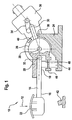
- the pedal 10 according to FIG. 1 is designed as an accelerator pedal of a motor vehicle and to actuate by a force 12, in particular a foot force, of a driver. By actuating the pedal 10, the driver controls the speed of the motor vehicle.
- the driver and the motor vehicle are in the drawing not shown in detail.
- the pedal 10 comprises a pedal arm 14 with a first end region 16 and a second end region 18.
- the first end region 16 of the pedal arm 14 is pivotable about a first pivot axis 20, on which the pedal arm 14 indirectly is arranged.
- the first end region 16 of the pedal arm 14 has a pedal plate 22 on that of the force 12 of the driver of the driver, not shown Motor vehicle is also actuated, not shown.
- the second end region 18 of the pedal arm 14 is in a housing via one 24 mounted two-armed lever 26 arranged on the first pivot axis 20, which is also the pivot axis 20 of the two-armed lever 26.
- the second end region 18 of the pedal arm 14 pivotable about a second pivot axis 32 on a first lever arm 28 of the two-armed lever 26 arranged.
- a second lever arm 30 of the two-armed Lever 26 acts on a lever element 34, which is a sensor unit 36 is assigned.
- the range of motion of the second lever arm 30 of the lever 26 is limited by an idle stop 38 and a full load stop 40.
- Limiting the range of motion of the second lever arm 30 of the two-armed lever 26 also applies to the first lever arm 28 of the two-armed Lever 26, since the first lever arm 28 rotatably with the second lever arm 30 is connected. Since the first lever arm 28 of the two-armed lever 26 is rigidly connected to the second lever arm 30 of the two-armed lever 26 and the range of movement of the second lever arm 30 of the two-armed lever 26 is limited by an idle stop 38, the idle stop limits 38 also the start position of the pedal arm 14. The end position of the pedal arm 14 is limited by an external end stop 42.
- the pedal arm 14 is above the first lever arm 28 of the two-armed lever 26 can be pivoted back into its starting position by a first return spring element 44 applied.
- the first return spring element 44 is on the one hand on the housing 24 and on the other hand on a pedal arm stop 46 supported, the rotationally fixed to the first lever arm 28 of the two-armed lever 26 is connected.
- the first return spring element 44 serves at the same time Generation of a mechanical hysteresis for the pedal 10. This will achieved that the first return spring element 44 when pressing down Pedal arms 14 by the external force 12 of the external force 12 with increasing Pushing down the pedal arm 14 increasing resistance opposes.
- first lever arm 28 of the two-armed lever 26 is immediate acted against the pedal arm 14.
- the first return spring element 44 and the second return spring element 48 are shown only schematically in the drawing.
- the second return spring element 48 is designed so that, in contrast to the first return spring element 44 a greater force is required to the second return spring element 48 push down.
- FIG 1 shows the pedal arm 14 of the pedal 10 in its starting position.
- Figure 2 is the pedal arm 14 is shown in its intermediate position. In the intermediate position the pedal arm 14 is deflected by an angle L1 with respect to the starting position. In this intermediate position, the first lever arm 28 of the two-armed Lever 26 on the pedal arm 14. The second lever arm 30 of the two-armed Lever 26 touches the full load stop in the intermediate position of the pedal arm 14 40.
- the first return spring element 44 is in this position of the pedal arm 14 compressed.
- the second return spring element 48 is only partially or not at all. In other words: The second return spring element 48 is designed so that it is in the range of motion of the pedal arm 14 from the starting position to the intermediate position remains almost unchanged in its shape.
- the second lever arm 30 of the two-armed lever 26 lies during the movement of the pedal arm 14 from the intermediate position to the end position on the Full load stop 40 on. As a result, it follows firmly with the second lever arm 30 of the two-armed lever 26 coupled first lever arm 28 of the two-armed Lever 26 not the movement of the pedal arm 14.
- the first lever arm 28 of the two-armed lever 26 is in the position of the intermediate position of the pedal arm 14 held by the full load stop 40.
- the pedal arm 14 moves upon action the external force 12 on the pedal plate 22 further counterclockwise, since the pedal arm 14 on the second pivot axis 32 on the first Lever arm 28 of the lever 26 is arranged.
- the sensor unit detects 36 not the movement of the pedal arm 14 from the intermediate position to the end position of the pedal arm 14.
- the one detectable by the sensor unit 36 The range of movement of the pedal arm 14 is thus in the range of Starting position of the pedal arm 14 to the intermediate position of the pedal arm 14 established.
- the sensor unit 36 is already before the pedal is installed 10 in, for example, a motor vehicle relative to the range of motion of the pedal arm 14 of the pedal 10 adjustable.
- the sensor unit 36 is thereby of the idle stop 38 and the full load stop 40 relative to the range of motion of the pedal arm 14 adjustable.
- the pedal 10 is almost fully pre-assembled.
- the pedal arm 14 is over the range detectable by the sensor unit 36 movable from the intermediate position to the end position. This is reliably ensures that the pedal arm 14 also particularly strong external Intercept forces 12. If the pedal 10 had no external end stop 42, the housing 24 would have the forces acting on the pedal arm 14 intercept completely. This would make the housing particularly stable 24 require.
- the decoupling of the detection area of the sensor unit 36 and the full range of motion of the pedal arm 14 of the pedal 10 particularly reliably avoids a signal overshoot in the Sensor unit 36. Furthermore, the pedal 10 can be removed almost completely, whereby the sensor unit 36 already in the factory relative to the range of motion the pedal arm 14 is pre-adjustable.
Landscapes
- Engineering & Computer Science (AREA)
- Transportation (AREA)
- Mechanical Engineering (AREA)
- Physics & Mathematics (AREA)
- General Physics & Mathematics (AREA)
- Automation & Control Theory (AREA)
- Chemical & Material Sciences (AREA)
- Combustion & Propulsion (AREA)
- Mechanical Control Devices (AREA)
- Auxiliary Drives, Propulsion Controls, And Safety Devices (AREA)
Abstract
Description
- Fig.: 1
- schematisch ein Pedal in einer Startstellung,
- Fig.: 2
- schematisch das Pedal gemäß Fig. 1 in einer Zwischenstellung und
- Fig.: 3
- schematisch das Pedal gemäß den Fig. 1 u. 2 in einer Endstellung.
Claims (4)
- Pedal (10), insbesondere für ein Kraftfahrzeug, mit einem Pedalarm (14), welcher an seinem ersten Endbereich (16) von einer Kraft (12), insbesondere einer Fußkraft, auslenkbar und an seinem zweiten Endbereich (18) um eine Schwenkachse (20) schwenkbar ist, wobei die Schwenkachse (20) an einem ersten Hebelarm (28) eines in einem Gehäuse (24) angeordneten Hebels (26) gelagert ist und die Schwenkbewegung des Pedalarms (14) über einen zweiten Hebelarm (30) des Hebels (26) von einer Sensoreinheit (36) erfaßbar ist, wobei der Pedalarm (14) von einer Startstellung über eine Zwischenstellung in eine durch einen Endanschlag (42) bestimmte Endstellung verschwenkbar ist, dadurch gekennzeichnet, daß die Verschwenkung des Pedalarms (14) von der Startstellung bis zu der Zwischenstellung mit einer Verschwenkung des Hebels (26) gekoppelt und von der Sensoreinheit (36) erfaßbar ist, wobei die Startstellung des Pedalarms (14) als Anfangsposition und die Zwischenstellung des Pedalarms (14) als Endposition für die Sensoreinheit (36) erfaßbar ist, und daß die Verschwenkung des Pedalarms (14) von der Zwischenstellung bis zu der Endstellung von einer Verschwenkung des Hebels (26) entkoppelt ist.
- Pedal (10) nach Anspruch 1, dadurch gekennzeichnet, daß der Verschwenkungsbereich des Hebels (26) von einem Leerlaufanschlag (38), und einem Vollastanschlag (40), begrenzt ist.
- Pedal (10) nach Anspruch 1 oder 2 dadurch gekennzeichnet, daß der Pedalarm (14) in dem Bewegungsbereich zwischen der Startstellung und der Zwischenstellung über ein an dem Gehäuse (24) abgestütztes erstes Rückstellfederelement (44) mit dem ersten Hebelarm (28) des Hebels (26) gekoppelt ist.
- Pedal (10) nach einem der Ansprüche 1 bis 3 dadurch gekennzeichnet, daß der Pedalarm (14) in dem Bewegungsbereich zwischen der Zwischenstellung und der Endstellung von einem an einem Pedalarmanschlag (46) abgestützten zweiten Rückstellfederelement (48) zurückschwenkbar beaufschlagt ist, wobei der Pedalarmanschlag (46) drehfest mit dem ersten Hebelarm (28) des Hebels (26) verbunden ist.
Applications Claiming Priority (2)
| Application Number | Priority Date | Filing Date | Title |
|---|---|---|---|
| DE10107899 | 2001-02-20 | ||
| DE2001107899 DE10107899A1 (de) | 2001-02-20 | 2001-02-20 | Pedal |
Publications (3)
| Publication Number | Publication Date |
|---|---|
| EP1233322A2 true EP1233322A2 (de) | 2002-08-21 |
| EP1233322A3 EP1233322A3 (de) | 2002-09-11 |
| EP1233322B1 EP1233322B1 (de) | 2007-12-12 |
Family
ID=7674702
Family Applications (1)
| Application Number | Title | Priority Date | Filing Date |
|---|---|---|---|
| EP20020003498 Expired - Lifetime EP1233322B1 (de) | 2001-02-20 | 2002-02-15 | Pedal |
Country Status (2)
| Country | Link |
|---|---|
| EP (1) | EP1233322B1 (de) |
| DE (2) | DE10107899A1 (de) |
Cited By (1)
| Publication number | Priority date | Publication date | Assignee | Title |
|---|---|---|---|---|
| US20140366678A1 (en) * | 2013-06-12 | 2014-12-18 | Cts Corporation | Vehicle Pedal Assembly Including Pedal Arm Stub with Inserts for Actuator Bar |
Family Cites Families (6)
| Publication number | Priority date | Publication date | Assignee | Title |
|---|---|---|---|---|
| IT1031957B (it) * | 1975-02-21 | 1979-05-10 | Ind Napoletana Costpuzione Aut | Pedale comando acceleratore per autoveicoli |
| DE19504971A1 (de) * | 1995-02-15 | 1996-08-22 | Vdo Schindling | Fahrpedal für eine Leistungssteuerung einer Brennkraftmaschine |
| SE505913C2 (sv) * | 1996-01-30 | 1997-10-20 | Scania Cv Ab | Pedalanordning för fordon |
| JPH1159219A (ja) * | 1997-08-21 | 1999-03-02 | Aisan Ind Co Ltd | アクセルペダル装置 |
| DE19813845A1 (de) * | 1998-03-28 | 1999-10-07 | Mannesmann Vdo Ag | Pedalwerk |
| US6186025B1 (en) * | 1999-03-24 | 2001-02-13 | Teleflex, Inc. | Break away pedal |
-
2001
- 2001-02-20 DE DE2001107899 patent/DE10107899A1/de not_active Withdrawn
-
2002
- 2002-02-15 DE DE50211331T patent/DE50211331D1/de not_active Expired - Fee Related
- 2002-02-15 EP EP20020003498 patent/EP1233322B1/de not_active Expired - Lifetime
Non-Patent Citations (1)
| Title |
|---|
| None |
Cited By (3)
| Publication number | Priority date | Publication date | Assignee | Title |
|---|---|---|---|---|
| US20140366678A1 (en) * | 2013-06-12 | 2014-12-18 | Cts Corporation | Vehicle Pedal Assembly Including Pedal Arm Stub with Inserts for Actuator Bar |
| CN105308531A (zh) * | 2013-06-12 | 2016-02-03 | Cts公司 | 包括具有用于致动器杆的衬套的踏板臂轴头的车辆踏板组件 |
| CN105308531B (zh) * | 2013-06-12 | 2017-05-10 | Cts公司 | 包括具有用于致动器杆的衬套的踏板臂轴头的车辆踏板组件 |
Also Published As
| Publication number | Publication date |
|---|---|
| EP1233322B1 (de) | 2007-12-12 |
| DE10107899A1 (de) | 2002-08-22 |
| EP1233322A3 (de) | 2002-09-11 |
| DE50211331D1 (de) | 2008-01-24 |
Similar Documents
| Publication | Publication Date | Title |
|---|---|---|
| DE69920115T2 (de) | Pedalmechanismus | |
| EP1428714B1 (de) | Fahrpedalmodul | |
| DE3641244C2 (de) | ||
| DE10121317B4 (de) | Pedaleinrichtung | |
| DE19536699A1 (de) | Fahrpedalmodul | |
| DE102004025829B4 (de) | Pedaleinheit, Pedalbaugruppe und Kraftfahrzeug | |
| DE102008054625A1 (de) | Fahrpedalmodul | |
| DE10234170A1 (de) | Beschleunigungspedalvorrichtung und Verfahren zum Einstellen einer Beschleunigungspedalvorrichtung | |
| EP0123731B1 (de) | Einrichtung zur Übertragung der Stellposition eines Sollwertgebers | |
| DE19939809A1 (de) | Fahrpedalmodul | |
| DE19939810A1 (de) | Fahrpedalmodul | |
| EP2785555B1 (de) | Pedalwertgeberanordnung | |
| DE10126194A1 (de) | Verstellbares Fußhebelwerk | |
| WO2004108464A1 (de) | Verfahren zur einstellung der auf ein fahrpedal eines kraftfahrzeugs wirkenden rückstellkraft | |
| EP1233322B1 (de) | Pedal | |
| EP1233320B1 (de) | Pedal | |
| EP1233323B1 (de) | Pedal | |
| EP1235133B1 (de) | Pedal | |
| DE10216317A1 (de) | Fahrgeschwindigkeitssteuereinrichtung für ein Kraftfahrzeug | |
| DE3924604A1 (de) | Zugkraftregelanlage | |
| DE102022118394A1 (de) | Reibflächengeometrie für Pedalsensoren | |
| DE102020003809A1 (de) | Zusatzpedalanordnung für einen Kraftwagen | |
| EP0478884B1 (de) | Lastverstelleinrichtung | |
| DE69508900T2 (de) | Pedalbetätigungsvorrichtung zur Steuerung des Bowdenzugs der Drosselklappe einer Brennstoffzufuhrvorrichtung für Brennkraftmaschine | |
| DE4015423A1 (de) | Motorsteuereinrichtung |
Legal Events
| Date | Code | Title | Description |
|---|---|---|---|
| PUAI | Public reference made under article 153(3) epc to a published international application that has entered the european phase |
Free format text: ORIGINAL CODE: 0009012 |
|
| PUAL | Search report despatched |
Free format text: ORIGINAL CODE: 0009013 |
|
| AK | Designated contracting states |
Kind code of ref document: A2 Designated state(s): AT BE CH CY DE DK ES FI FR GB GR IE IT LI LU MC NL PT SE TR |
|
| AX | Request for extension of the european patent |
Free format text: AL;LT;LV;MK;RO;SI |
|
| AK | Designated contracting states |
Kind code of ref document: A3 Designated state(s): AT BE CH CY DE DK ES FI FR GB GR IE IT LI LU MC NL PT SE TR |
|
| AX | Request for extension of the european patent |
Free format text: AL;LT;LV;MK;RO;SI |
|
| RIC1 | Information provided on ipc code assigned before grant |
Free format text: 7G 05G 1/14 A, 7B 60T 7/06 B |
|
| 17P | Request for examination filed |
Effective date: 20021007 |
|
| AKX | Designation fees paid |
Designated state(s): DE FR IT |
|
| R17C | First examination report despatched (corrected) |
Effective date: 20060921 |
|
| GRAP | Despatch of communication of intention to grant a patent |
Free format text: ORIGINAL CODE: EPIDOSNIGR1 |
|
| GRAS | Grant fee paid |
Free format text: ORIGINAL CODE: EPIDOSNIGR3 |
|
| GRAA | (expected) grant |
Free format text: ORIGINAL CODE: 0009210 |
|
| RAP1 | Party data changed (applicant data changed or rights of an application transferred) |
Owner name: SIEMENS VDO AUTOMOTIVE AG |
|
| AK | Designated contracting states |
Kind code of ref document: B1 Designated state(s): DE FR IT |
|
| REF | Corresponds to: |
Ref document number: 50211331 Country of ref document: DE Date of ref document: 20080124 Kind code of ref document: P |
|
| RAP2 | Party data changed (patent owner data changed or rights of a patent transferred) |
Owner name: VDO AUTOMOTIVE AG |
|
| ET | Fr: translation filed | ||
| RAP2 | Party data changed (patent owner data changed or rights of a patent transferred) |
Owner name: CONTINENTAL AUTOMOTIVE GMBH |
|
| PLBE | No opposition filed within time limit |
Free format text: ORIGINAL CODE: 0009261 |
|
| STAA | Information on the status of an ep patent application or granted ep patent |
Free format text: STATUS: NO OPPOSITION FILED WITHIN TIME LIMIT |
|
| 26N | No opposition filed |
Effective date: 20080915 |
|
| PGFP | Annual fee paid to national office [announced via postgrant information from national office to epo] |
Ref country code: DE Payment date: 20090219 Year of fee payment: 8 |
|
| PGFP | Annual fee paid to national office [announced via postgrant information from national office to epo] |
Ref country code: IT Payment date: 20090220 Year of fee payment: 8 |
|
| PGFP | Annual fee paid to national office [announced via postgrant information from national office to epo] |
Ref country code: FR Payment date: 20090213 Year of fee payment: 8 |
|
| REG | Reference to a national code |
Ref country code: FR Ref legal event code: ST Effective date: 20101029 |
|
| PG25 | Lapsed in a contracting state [announced via postgrant information from national office to epo] |
Ref country code: FR Free format text: LAPSE BECAUSE OF NON-PAYMENT OF DUE FEES Effective date: 20100301 |
|
| PG25 | Lapsed in a contracting state [announced via postgrant information from national office to epo] |
Ref country code: DE Free format text: LAPSE BECAUSE OF NON-PAYMENT OF DUE FEES Effective date: 20100901 |
|
| PG25 | Lapsed in a contracting state [announced via postgrant information from national office to epo] |
Ref country code: IT Free format text: LAPSE BECAUSE OF NON-PAYMENT OF DUE FEES Effective date: 20100215 |