EP1233133A2 - Schliessfolgeregler - Google Patents
Schliessfolgeregler Download PDFInfo
- Publication number
- EP1233133A2 EP1233133A2 EP02003533A EP02003533A EP1233133A2 EP 1233133 A2 EP1233133 A2 EP 1233133A2 EP 02003533 A EP02003533 A EP 02003533A EP 02003533 A EP02003533 A EP 02003533A EP 1233133 A2 EP1233133 A2 EP 1233133A2
- Authority
- EP
- European Patent Office
- Prior art keywords
- clamping
- sequence controller
- controller according
- locking
- leaf
- Prior art date
- Legal status (The legal status is an assumption and is not a legal conclusion. Google has not performed a legal analysis and makes no representation as to the accuracy of the status listed.)
- Withdrawn
Links
- 210000003813 thumb Anatomy 0.000 claims description 14
- 238000010276 construction Methods 0.000 description 1
- 238000011161 development Methods 0.000 description 1
- 230000018109 developmental process Effects 0.000 description 1
- 210000003746 feather Anatomy 0.000 description 1
- 210000003127 knee Anatomy 0.000 description 1
- 238000012986 modification Methods 0.000 description 1
- 230000004048 modification Effects 0.000 description 1
- 230000036316 preload Effects 0.000 description 1
- 230000000630 rising effect Effects 0.000 description 1
- 230000007704 transition Effects 0.000 description 1
Images





Classifications
-
- E—FIXED CONSTRUCTIONS
- E05—LOCKS; KEYS; WINDOW OR DOOR FITTINGS; SAFES
- E05F—DEVICES FOR MOVING WINGS INTO OPEN OR CLOSED POSITION; CHECKS FOR WINGS; WING FITTINGS NOT OTHERWISE PROVIDED FOR, CONCERNED WITH THE FUNCTIONING OF THE WING
- E05F5/00—Braking devices, e.g. checks; Stops; Buffers
- E05F5/12—Braking devices, e.g. checks; Stops; Buffers specially for preventing the closing of a wing before another wing has been closed
-
- E—FIXED CONSTRUCTIONS
- E05—LOCKS; KEYS; WINDOW OR DOOR FITTINGS; SAFES
- E05Y—INDEXING SCHEME ASSOCIATED WITH SUBCLASSES E05D AND E05F, RELATING TO CONSTRUCTION ELEMENTS, ELECTRIC CONTROL, POWER SUPPLY, POWER SIGNAL OR TRANSMISSION, USER INTERFACES, MOUNTING OR COUPLING, DETAILS, ACCESSORIES, AUXILIARY OPERATIONS NOT OTHERWISE PROVIDED FOR, APPLICATION THEREOF
- E05Y2201/00—Constructional elements; Accessories therefor
- E05Y2201/60—Suspension or transmission members; Accessories therefor
- E05Y2201/622—Suspension or transmission members elements
- E05Y2201/686—Rods, links
-
- E—FIXED CONSTRUCTIONS
- E05—LOCKS; KEYS; WINDOW OR DOOR FITTINGS; SAFES
- E05Y—INDEXING SCHEME ASSOCIATED WITH SUBCLASSES E05D AND E05F, RELATING TO CONSTRUCTION ELEMENTS, ELECTRIC CONTROL, POWER SUPPLY, POWER SIGNAL OR TRANSMISSION, USER INTERFACES, MOUNTING OR COUPLING, DETAILS, ACCESSORIES, AUXILIARY OPERATIONS NOT OTHERWISE PROVIDED FOR, APPLICATION THEREOF
- E05Y2900/00—Application of doors, windows, wings or fittings thereof
- E05Y2900/10—Application of doors, windows, wings or fittings thereof for buildings or parts thereof
- E05Y2900/13—Type of wing
- E05Y2900/132—Doors
Definitions
- the invention relates to a closing sequence controller for a fixed leaf and a door comprising a moving wing, in particular a fire door, according to the preamble of claim 1.
- closing sequence controllers are used, which are always the order required for the aforementioned proper closing ensure the transitions of the two wings into the closed position.
- There is a certain order of closing movement of both door leaves also necessary for the lock which is usually provided with a lock Only let the active leaf reach the closed position, if the one forming the door stop, usually the striking plate or the same standing leaf is closed.
- a closing sequence controller specified in the preamble of claim 1 Art is known from DE 33 36 739 C2.
- this known closing sequence controller has this Slider of the active leaf and the locking member on their facing sides a saw toothing, the inclined tooth surfaces of which in a Enabling opening of the active leaf with the locking element in the unlocked position Show direction.
- the inactive leaf works with an axially adjustable one Push member together to solve the finding of the Slider acts on the locking member.
- the generic closing sequence controller is a safe closing sequence control even if the door leaves are kept open for a longer time a simplification of the structure of the generic closing sequence controller desirable.
- the closing sequence controller according to the invention is characterized by an uncomplicated one Structure with few components, which nevertheless always ensures that the passive leaf in front of the active leaf is in the closed position is transferred. This is mainly achieved in that the locking member is always biased towards the locked position so that it is one deliberate solution to this locked position needs to move the active leaf into the To be able to move the closed position.
- a locking mechanism has a clamping body that is clamping on a clamping rod that is operatively connected to the active leaf acts. At the same time, the passive leaf stands with a release bar in operative connection, with the help of the clamping between the clamping body and the clamp rod can be lifted.
- FIG. 1 is an example in a wall or a wall-fixed door frame 7 shows a door 2 with two wings, one wing 3 the passive wing and a wing 4 forms the active wing.
- Both the passive leaf 3 and the active leaf 4 are equipped with door closers 19 and 20, the door leaves of the illustrated embodiment each are connected to an overhead door closer, whose not shown Closer shaft each with a swivel arm 5 or 6 rotatably connected is.
- the free end of the swivel arm 5 or 6 is at a Door frame 7 above the wings 3, 4 arranged rail-like sliding guide 10 led.
- Rotary leaf drives can also be used instead of the overhead door closer be used.
- each swivel arm 5 or 6 is on a not shown Pin a slider 9 or 11 arranged in the guide chamber the sliding guide 10 engages longitudinally.
- the closing sequence controller 1 according to the invention, that according to that described in FIG. 1 Door arrangement can be used is described in more detail below described. It is understood that the invention Closing sequence controller 1 in addition to the special features of the present Features making up the invention of course all other features known per se, such as mechanical or electrical drives Type, possibly required sensors and control devices can have.
- the closing sequence controller 1 initially has a first one Slider 9 on that with the door frame side end of the swivel arm 6 of the active leaf 4 is connected. As already explained, this is the first Slider 9 slidable in the slide guide 10 attached in the door frame 7 stored.
- the second slider 11 is with the door frame end of Swivel arm 5 of the passive leaf 3 connected. It is also in the Sliding guide 10 slidably arranged.
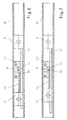
- the slide 9 of the active leaf has 4, a clamping rod 15 which extends through a base body 13 is guided, which is fixed in the sliding guide 10.
- the slider 11 has a thrust member 12, which is shown in the Embodiment is designed as a trigger rod with the slider 11 is firmly connected.
- the trigger rod 12 in turn has one Tip 16 on with a locking member 8 in the base body 13 in and can be disengaged.
- the trigger rod 12 in the Base body 13 inserted and the tip 16 is preferably beveled.
- the locking member 8 is always biased towards its locking position, for which a suitable one not shown in the figures Spring element can be provided.
- This circular Eccentric 8 has a friction surface 14 and is not closer by that Shown spring element, the clamping position shown in Fig. 2, preloaded, which represents the end position of the circular eccentric 8.
- the trigger rod 12 forming the push rod Slider 11 also runs through a suitable recess in the base body 13 and can release the clamping of the clamping rod 15.
- the closed position of the door 2 is shown.
- the release rod 12 pushes the circular Eccentric 8 against the spring force from its clamping position out.
- the trigger rod 12 can have a beveled tip 16 exhibit.
- the slider 9 is the Active leaf 4 of door 2 freely movable. If the active leaf 4 is opened, it can be closed without the closing sequence controller 1.
- the passive leaf 3 is opened, the slider 11 of the passive leaf 3 is removed from a zero position and thus the release rod 12 from the circular eccentric 8th
- the circular eccentric 8 follows due to its spring preload Release rod 12 until it is in its clamping position. In this there is no contact between the trip bar 12 and the circular one Eccentric 8. In this clamping position of the circular eccentric 8 can the active leaf 4 and thus the associated slide 9 only still move in the opening direction. There is a movement in the closing direction not possible because the circular eccentric 8 clamps the clamping rod 15 and thus blocks their movement in the closing direction.
- the holding force can preferably be between the circular eccentric 8 and the clamping rod 15 can be increased by a wedge-shaped engagement.
- the circular eccentric 8 on the one forming the active surface Friction surface 14 have a wedge-shaped contour, while the clamping rod 15 provided with a corresponding wedge-shaped recess can be.
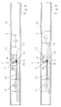
- the locking member 8 as one in the base body 13 rotatably mounted toggle lever.
- the knee lever forms thereby an assembly that a rotatably mounted lever 21 and one Clamping shoe 22 rotatably mounted on the lever 21 with a friction surface 23 having.
- the toggle lever is due to the already mentioned spring element, not shown, preferably in the form of a torsion spring, and is biased thus always in the direction of its end position, which represents the clamping position, pressed.
- Clamping rod 15 can be on one side on the base body 13 support, on the other hand, the clamping rod 15 with the toggle lever 8 form an effective pairing in the clamping position.
- the trigger rod 12 attached to the slider 11 can clamp the clamp rod 15 of the slider 9.
- the active leaf In this position (clamping position) of the locking member 8, the active leaf can be 4 and thus the associated slide 9 only in the opening direction move. A movement in the closing direction is not possible because the locking member 8 clamps the clamping rod 15 and so their movement prevents in the closing direction. If according to Fig. 11 on the trigger rod 12 of the slider 11, the locking member 8 itself from the clamping position triggers, the slider 9 can, however, return to its starting position move, which ensures the desired closing sequence, according to which then first the passive leaf 3 and then the active leaf 4 into the respective Closed position is transferred.
- the holding force of the locking member 8 is in the illustrated embodiment preferably increased in that a wedge-shaped friction surface 23 is provided, which moreover with a wedge-shaped not shown Deepening of the clamping rod 15 can cooperate.
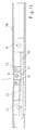
- this is in the Base body 13 rotatably mounted locking member 8 in the manner of a thumb (Lever) trained and thus provides a rotatable thumb
- This friction thumb 8 has a friction surface 14 and is through the spring element, not shown, that shown in FIG. 2 Preloaded clamping position, which represents the end position of the friction thumb 8.
- the clamping rod passed through the recess in the base body 13 15, which in the illustrated embodiment in the position in 12 and 13 also runs through the slider 11, can be supported on one side on the base body 13 and on the on the other hand, in the clamping position, an effective combination with the rubbing thumb 8 form.
- the trigger rod 12 of the slider 11 forming the thrust member extends also through a suitable recess in the base body 13 and can release the clamping of the clamping rod 15.
- the slider 11 of the passive leaf 3 is removed from a zero position and thus the release rod 12 from the rubbing thumb 8.
- the rubbing thumb 8 follows the release rod 12 due to its spring bias until it is in its clamping position. In this there is no contact between the release rod 12 and the friction thumb 8.
- the active leaf 4 and thus the associated one Only move slider 9 in the opening direction. A movement in the closing direction is not possible because the friction thumb 8 Clamping rod 15 clamps and so their movement in the closing direction blocked.
- the holding force between the friction thumb 8 and the Clamping rod 15 can be increased by a wedge-shaped engagement.
- the friction thumb 8 on the friction surface 14 forming the active surface have a wedge-shaped contour, while the clamping rod 15 with a corresponding wedge-shaped recess can be provided.
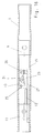
- the closing sequence controller comprises again a base body 13 in the sliding guide 10 between the fixed leaf slider 11 and the active leaf slide 9 is provided.
- the base body 4 is a preferably a wedge-shaped clamping body 23 and a rotatably mounted clamping shoe 24 is arranged. Clamp shoe 24 and clamp body 23 together form the locking member 8.
- the clamp body 23 has an inclined surface 25 with which it on the clamping shoe 24 is present. The inclined surface 25 is arranged so that it is in Direction towards the active leaf slide 9 rises, d. H. to the right in Fig. 1.
- the clamping rod 15 is fixed, which are in a movement of the active leaf slide 9 in the sliding guide 1 moved back and forth with this.
- the clamp rod 15 goes through the base body 13 and preferably also through the fixed leaf slide 11 through. Furthermore, this is on the passive leaf slider 11 Thrust member 12 fixedly attached, which is in a movement of the passive leaf slider 11 also moved.
- the clamping body 23 is under the bias of a spring 26, which the clamping body 23 permanently loaded in its clamping position, so that the clamping body 23 with a horizontal surface 27 on the clamping rod 15 acts to prevent them from moving.
- the clamp bar 15 is based either on the sliding guide 1 or on Base body 13 from. That arranged on the passive leaf slide 11 Push element 12 can move the fixed-wing slide 11 act on the clamping body 23 to this from its clamping position move away.
- the sprag 23 a wedge-shaped contour and the clamping rod 15 and / or the Clamping shoe 24 have a corresponding wedge-shaped recess.
- Fig. 15 the position of the closing sequence controller 1 is in the zero position Door shown, in which both door leaves are closed.
- the passive leaf slide 11 and the active leaf slide 9 are in their starting position and the thrust member arranged on the fixed leaf slide 11 12 pushes the clamping body 23 out of its clamping position and prevents it such a clamping of the clamping rod 15 by the clamping body 23.
- the active leaf slide can 9 and thus the active leaf can be moved freely.
- the passive leaf slide is removed 11 from its zero position and takes the thrust member 12 with it.
- the clamping body 23 follows the thrust member 12 due to the spring 26 until it is in the clamping position and onto the clamping rod 15 acts. In this state there is no longer any contact between the clamping body 23 and the thrust member 12. Due to the in Opening direction of the active leaf rising inclined surface 25 des Clamping body 23 can be in this state of the active leaf and thus the active leaf slide 9 only in the opening direction (to the right in Fig. 16) move. A movement in the closing direction (to the left in Fig. 16) is no longer possible since the clamping body 23 the clamping rod 15 jammed and thus prevents their movement in the closing direction.
Landscapes
- Specific Sealing Or Ventilating Devices For Doors And Windows (AREA)
- Power-Operated Mechanisms For Wings (AREA)
- Closing And Opening Devices For Wings, And Checks For Wings (AREA)
Abstract
Description
- Figur 1:
- Eine zweiflügelige Tür mit einem Schließfolgeregler und jedem Türflügel zugehörigen Obentürschließern, in einer schematischen, perspektivischen Ansicht und
- Figur 2 - 7:
- schematisch stark vereinfachte Darstellungen eines Teiles des erfindungsgemäßen Schließfolgereglers im Bereich einer Gleitschiene mit einem Sperrglied zur Erläuterung des Aufbaues und der Funktionsweise in unterschiedlichen Stellungen des Gang- und Standflügels einer ersten Ausführungsform,
- Figur 8 - 11:
- schematisch stark vereinfachte Darstellungen eines Teiles des erfindungsgemäßen Schließfolgereglers im Bereich einer Gleitschiene mit einem Sperrglied zur Erläuterung des Aufbaues und der Funktionsweise in unterschiedlichen Stellungen des Gang- und Standflügels einer zweiten Ausführungsform,
- Figur 12 - 14:
- schematisch stark vereinfachte Darstellungen eines Teiles des erfindungsgemäßen Schließfolgereglers im Bereich einer Gleitschiene mit einem Sperrglied zur Erläuterung des Aufbaues und der Funktionsweise in unterschiedlichen Stellungen des Gang- und Standflügels einer dritten Ausführungsform,
- Figur 15 - 16:
- schematisch stark vereinfachte Darstellungen eines Teiles des erfindungsgemäßen Schließfolgereglers im Bereich einer Gleitschiene mit einem Sperrglied zur Erläuterung des Aufbaues und der Funktionsweise in unterschiedlichen Stellungen des Gang- und Standflügels einer vierten Ausführungsform.
- 1
- Schließfolgeregler
- 2
- Tür
- 3
- Standflügel
- 4
- Gangflügel
- 5, 6
- Schwenkarm
- 7
- Türrahmen
- 8
- Sperrglied
- 9
- Gleitstück
- 10
- Gleitführung
- 11
- Gleitstück
- 12
- Schubglied
- 13
- Grundkörper
- 14
- Reibfläche
- 15
- Klemmstange
- 16
- Spitze
- 19, 20
- Türschließer
- 21
- Hebel
- 22
- Klemmschuh
- 23
- Klemmkörper
- 24
- Klemmschuh
- 25
- geneigte Fläche
- 26
- Feder
- 27
- horizontale Fläche
Claims (22)
- Schließfolgeregler (1) für eine einen Standflügel (3) und einen Gangflügel (4) umfassende Tür (2), insbesondere Feuerschutztür, die über je einen Schwenkarm (5, 6) mit einem Türrahmen (7) verbunden sind, wobei der Schwenkarm (6) des Gangflügels (4) mittels eines vom Standflügel (3) freigebbaren Sperrglieds (8) feststellbar ist,mit einem ersten Gleitstück (9), das mit dem türrahmenseitigen Ende des Schwenkarmes (6) des Gangflügels (4) verbunden ist und das in einer im Türrahmen (7) angebrachten Gleitführung (10) verschiebbar ist, undmit einem zweiten Gleitstück (11), das mit dem türrahmenseitigen Ende des Schwenkarmes (5) des Standflügels (3) verbunden ist, das in der Gleitführung (10) verschiebbar ist und das ein mit dem Sperrglied (8) in und außer Eingriff bringbares Schubglied (12) aufweist, dadurch gekennzeichet,dass das Sperrglied (8) in Richtung auf seine Sperrstellung vorgespannt ist.
- Schließfolgeregler nach Anspruch 1, dadurch gekennzeichnet, dass das Sperrglied (8) durch ein Federelement vorgespannt ist.
- Schließfolgeregler nach Anspruch 2, dadurch gekennzeichnet, dass das Federelement als Drehfeder ausgebildet ist.
- Schließfolgeregler nach einem der Ansprüche 1 bis 3, dadurch gekennzeichnet, dass das Sperrglied (8) in einem Grundkörper (13) gelagert ist, der in der Gleitführung (10) fixierbar ist.
- Schließfolgeregler nach einem der Ansprüche 1 bis 4, dadurch gekennzeichnet, dass das Sperrglied (8) als kreisförmiger Exzenter ausgebildet ist, der eine Reibfläche (14) aufweist.
- Schließfolgeregler nach einem der Ansprüche 4 oder 5, dadurch gekennzeichnet, dass das Gleitstück (9) des Gangflügels (4) eine Klemmstange (15) aufweist, die durch den Grundkörper (13) hindurch geführt ist und mit der das Sperrglied (8) zusammenwirkt.
- Schließfolgeregler nach einem der Ansprüche 1 bis 6, dadurch gekennzeichnet, dass das Schubglied (12) als Auslösestange ausgebildet ist, deren vorzugsweise angeschrägte Spitze (16) mit dem Sperrglied (8) in und außer Eingriff bringbar ist.
- Schließfolgeregler nach Anspruch 7, dadurch gekennzeichnet, dass die Auslösestange (12) in dem Grundkörper (13) geführt ist.
- Schließfolgeregler nach einem der Ansprüche 5 bis 8, dadurch gekennzeichnet, dass der Exzenter (8) eine kreisförmige Kontur aufweist.
- Schließfolgeregler nach den Ansprüchen 1 bis 4, dadurch gekennzeichnet, dass das Sperrglied (8) einen drehbar gelagerten Hebel (21) aufweist, an dem ein drehbar gelagerter Klemmschuh (22) angeordnet ist.
- Schließfolgeregler nach den Ansprüchen 1 bis 4, dadurch gekennzeichnet, dass das Sperrglied (8) als Reibdaumen (Hebel) ausgebildet ist.
- Schließfolgeregler nach einem oder mehreren der vorhergehenden Ansprüche, dadurch gekennzeichnet, dass das Sperrglied (8) im Bereich einer Reibfläche (14) eine keilförmige Kontur aufweist.
- Schließfolgeregler nach den vorhergehenden Ansprüchen, dadurch gekennzeichnet, dass die Klemmstange (15) mindestens eine keilförmige Vertiefung zum Eingriff mit der keilförmigen Reibfläche (14) aufweist.
- Schließfolgeregler nach den Ansprüchen 1 bis 4, dadurch gekennzeichnet, dass der Sperrmechanismus einen Klemmkörper (23) aufweist, der klemmend auf die mit dem Gangflügel in Wirkverbindung stehende Klemmstange (15) einwirkt.
- Schließfolgeregler nach Anspruch 14, dadurch gekennzeichnet, dass der Klemmkörper (23) keilförmig ausgebildet ist und eine geneigte Fläche (25) aufweist, die in Richtung des Gangflügel-Gleitstückes (9) ansteigt.
- Schließfolgeregler nach einem der vorhergehenden Ansprüche, dadurch gekennzeichnet, dass der Klemmkörper (23) von einem vorzugsweise schwenkbar gelagerten Klemmschuh (24) beaufschlagt ist.
- Schließfolgeregler nach einem der vorhergehenden Ansprüche, dadurch gekennzeichnet, dass der Klemmkörper (23) federbelastet ist und eine Feder (26) den Klemmkörper (23) in seine Klemmposition drängt.
- Schließfolgeregler nach einem der vorhergehenden Ansprüche, dadurch gekennzeichnet, dass der Klemmkörper (23), der Klemmschuh (24) und die Feder (26) in dem Grundkörper (13) gelagert sind, welcher in der Gleitführung (1) zwischen dem Standflügel-Gleitstück (11) und dem Gangflügel-Gleitstück (9) einsetzbar ist.
- Schließfolgeregler nach einem der vorhergehenden Ansprüche, dadurch gekennzeichnet, dass der Klemmkörper (23) mit seiner geneigten Fläche (25) und dem Klemmschuh (24) eine erste Klemmpaarung bildet und mit seiner horizontalen Fläche (27) und der Klemmstange (15) eine zweite Klemmpaarung bildet.
- Schließfolgeregler nach einem der vorhergehenden Ansprüche, dadurch gekennzeichnet, dass sich die Klemmstange (12) mit ihrer dem Klemmkörper (23) gegenüberliegenden Seite an der Gleitführung (10) oder an dem Grundkörper (13) abstützt.
- Schließfolgeregler nach einem der vorhergehenden Ansprüche, dadurch gekennzeichnet, dass zwischen dem Klemmkörper (23) und der Schubstange (12) und/oder zwischen dem Klemmkörper (23) und dem Klemmschuh (24) ein keilförmiger Eingriff erfolgt.
- Schließfolgeregler nach Anspruch 21, dadurch gekennzeichnet, dass der Klemmkörper (23) mit einer keilförmigen Kontur und die Klemmstange (15) bzw. der Klemmschuh (24) mit einer keilförmigen Vertiefung versehen sind.
Applications Claiming Priority (8)
| Application Number | Priority Date | Filing Date | Title |
|---|---|---|---|
| DE10107787 | 2001-02-16 | ||
| DE10107783A DE10107783B4 (de) | 2001-02-16 | 2001-02-16 | Schliessfolgeregler |
| DE10107785 | 2001-02-16 | ||
| DE10107783 | 2001-02-16 | ||
| DE10107787A DE10107787B4 (de) | 2001-02-16 | 2001-02-16 | Schließfolgeregler |
| DE10107884 | 2001-02-16 | ||
| DE10107884A DE10107884B4 (de) | 2001-02-16 | 2001-02-16 | Schließfolgeregler |
| DE10107785A DE10107785B4 (de) | 2001-02-16 | 2001-02-16 | Schließfolgeregeler |
Publications (2)
| Publication Number | Publication Date |
|---|---|
| EP1233133A2 true EP1233133A2 (de) | 2002-08-21 |
| EP1233133A3 EP1233133A3 (de) | 2005-01-19 |
Family
ID=27437934
Family Applications (1)
| Application Number | Title | Priority Date | Filing Date |
|---|---|---|---|
| EP02003533A Withdrawn EP1233133A3 (de) | 2001-02-16 | 2002-02-15 | Schliessfolgeregler |
Country Status (1)
| Country | Link |
|---|---|
| EP (1) | EP1233133A3 (de) |
Cited By (2)
| Publication number | Priority date | Publication date | Assignee | Title |
|---|---|---|---|---|
| AT510683B1 (de) * | 2010-11-23 | 2012-06-15 | Walter Ing Degelsegger | Vorrichtung für das steuern der schliessfolge von zweiflügeligen schwenktüren |
| CN102877728A (zh) * | 2011-07-15 | 2013-01-16 | 台湾福兴工业股份有限公司 | 关门顺序控制器 |
Citations (2)
| Publication number | Priority date | Publication date | Assignee | Title |
|---|---|---|---|---|
| DE3336739C2 (de) | 1983-10-08 | 1988-01-28 | Dorma Gmbh + Co Kg, 5828 Ennepetal, De | |
| EP1111178A2 (de) * | 1999-12-24 | 2001-06-27 | Mektila 2000, S.L. | Schliessfolgeregler für eine zweiflügelige Tür |
Family Cites Families (1)
| Publication number | Priority date | Publication date | Assignee | Title |
|---|---|---|---|---|
| DE19545401A1 (de) * | 1995-12-06 | 1997-06-12 | Geze Gmbh & Co | Schließfolgesteuerung für eine zweiflügelige Tür |
-
2002
- 2002-02-15 EP EP02003533A patent/EP1233133A3/de not_active Withdrawn
Patent Citations (2)
| Publication number | Priority date | Publication date | Assignee | Title |
|---|---|---|---|---|
| DE3336739C2 (de) | 1983-10-08 | 1988-01-28 | Dorma Gmbh + Co Kg, 5828 Ennepetal, De | |
| EP1111178A2 (de) * | 1999-12-24 | 2001-06-27 | Mektila 2000, S.L. | Schliessfolgeregler für eine zweiflügelige Tür |
Cited By (4)
| Publication number | Priority date | Publication date | Assignee | Title |
|---|---|---|---|---|
| AT510683B1 (de) * | 2010-11-23 | 2012-06-15 | Walter Ing Degelsegger | Vorrichtung für das steuern der schliessfolge von zweiflügeligen schwenktüren |
| AT510683A4 (de) * | 2010-11-23 | 2012-06-15 | Walter Ing Degelsegger | Vorrichtung für das steuern der schliessfolge von zweiflügeligen schwenktüren |
| CN102877728A (zh) * | 2011-07-15 | 2013-01-16 | 台湾福兴工业股份有限公司 | 关门顺序控制器 |
| CN102877728B (zh) * | 2011-07-15 | 2015-07-08 | 台湾福兴工业股份有限公司 | 关门顺序控制器 |
Also Published As
| Publication number | Publication date |
|---|---|
| EP1233133A3 (de) | 2005-01-19 |
Similar Documents
| Publication | Publication Date | Title |
|---|---|---|
| DE2920581C2 (de) | Zusatzverriegelung, insbesondere Mittelverriegelung, für Fenster, Türen od.dgl. | |
| DE3336739C2 (de) | ||
| DE10347528B3 (de) | Türöffner | |
| EP0711896B1 (de) | Verschlussvorrichtung für Fenster, Türen od. dgl. | |
| EP1582673B1 (de) | Schliessblech für Fenster oder Fenstertüren | |
| WO2014195474A1 (de) | Türschliesser für einen flügel einer tür oder eines fensters | |
| WO2015003872A1 (de) | Beschlag für ein fenster, eine tür oder dergleichen mit einem kipp- und schiebbaren flügel | |
| EP3034728B1 (de) | Öffnungsbegrenzereinrichtung | |
| DE20219081U1 (de) | Schiebetür oder -tor, welches insbesondere als Brand- und Rauchschutzschiebetor ausgebildet ist | |
| EP0723060A1 (de) | Schliessfolgeregler | |
| DE10107785B4 (de) | Schließfolgeregeler | |
| DE10111732A1 (de) | Schliessfolgeregler für eine zweiflügelige Tür | |
| DE10107886B4 (de) | Schließfolgeregler | |
| EP1247931B1 (de) | Schliessfolgeregler | |
| DE10107888B4 (de) | Schließfolgeregler | |
| DE10107884B4 (de) | Schließfolgeregler | |
| EP1233131B1 (de) | Schliessfolgeregler | |
| EP3299551B1 (de) | Verriegelungsvorrichtung mit ausgleichsschieber und übertragungselement | |
| DE10107787B4 (de) | Schließfolgeregler | |
| DE10107783B4 (de) | Schliessfolgeregler | |
| DE10152676B4 (de) | Schließfolgeregler | |
| AT515398A1 (de) | Vorrichtung für das Steuern der Schließfolge von zweiflügeligen Schwenktüren | |
| DE102004062763A1 (de) | Schließfolgeregelung | |
| DE102007057218A1 (de) | Sicherungsvorrichtung für das Beschlagsystem von parallel abstellbaren Kippschiebetüren | |
| EP1703061A2 (de) | Schliessfolgeregler |
Legal Events
| Date | Code | Title | Description |
|---|---|---|---|
| PUAI | Public reference made under article 153(3) epc to a published international application that has entered the european phase |
Free format text: ORIGINAL CODE: 0009012 |
|
| AK | Designated contracting states |
Kind code of ref document: A2 Designated state(s): AT BE CH CY DE DK ES FI FR GB GR IE IT LI LU MC NL PT SE TR |
|
| AX | Request for extension of the european patent |
Free format text: AL;LT;LV;MK;RO;SI |
|
| PUAL | Search report despatched |
Free format text: ORIGINAL CODE: 0009013 |
|
| AK | Designated contracting states |
Kind code of ref document: A3 Designated state(s): AT BE CH CY DE DK ES FI FR GB GR IE IT LI LU MC NL PT SE TR |
|
| AX | Request for extension of the european patent |
Extension state: AL LT LV MK RO SI |
|
| 17P | Request for examination filed |
Effective date: 20050719 |
|
| AKX | Designation fees paid |
Designated state(s): AT BE CH CY DE DK ES FI FR GB GR IE IT LI LU MC NL PT SE TR |
|
| 17Q | First examination report despatched |
Effective date: 20051220 |
|
| STAA | Information on the status of an ep patent application or granted ep patent |
Free format text: STATUS: THE APPLICATION HAS BEEN WITHDRAWN |
|
| 18W | Application withdrawn |
Effective date: 20070504 |