EP1232719A2 - Auswringvorrichtung für Wischgerät - Google Patents
Auswringvorrichtung für Wischgerät Download PDFInfo
- Publication number
- EP1232719A2 EP1232719A2 EP02001480A EP02001480A EP1232719A2 EP 1232719 A2 EP1232719 A2 EP 1232719A2 EP 02001480 A EP02001480 A EP 02001480A EP 02001480 A EP02001480 A EP 02001480A EP 1232719 A2 EP1232719 A2 EP 1232719A2
- Authority
- EP
- European Patent Office
- Prior art keywords
- wringing
- roller
- mop
- tool
- aforesaid
- Prior art date
- Legal status (The legal status is an assumption and is not a legal conclusion. Google has not performed a legal analysis and makes no representation as to the accuracy of the status listed.)
- Granted
Links
Images


Classifications
-
- A—HUMAN NECESSITIES
- A47—FURNITURE; DOMESTIC ARTICLES OR APPLIANCES; COFFEE MILLS; SPICE MILLS; SUCTION CLEANERS IN GENERAL
- A47L—DOMESTIC WASHING OR CLEANING; SUCTION CLEANERS IN GENERAL
- A47L13/00—Implements for cleaning floors, carpets, furniture, walls, or wall coverings
- A47L13/10—Scrubbing; Scouring; Cleaning; Polishing
- A47L13/50—Auxiliary implements
- A47L13/58—Wringers for scouring pads, mops, or the like, combined with buckets
- A47L13/60—Wringers for scouring pads, mops, or the like, combined with buckets with squeezing rollers
Definitions
- Some of the afore described wringing tools, with the roller working against a bent wringing surface, to improve their functioning, are provided with springs inside each of their oscillating arms; these springs exert a thrust force on the movable roller which presses against the wringing surface.
- the overall dimensions of the box constituting the wringing tool's formwork must be contained both as regards width and as regards length because they do not have to go beyond some fixed and already consolidated values of the structures the wringing tools are to be applied on.
- wringing tools there are the Japanese model 52.347, the wringing tool of the US patent 4,852,207 of Yamane, the wringing tool of the EP 480 327 of VDM s.r.l.
- One of the first problems is caused by the fact that the oscillation angle of the levers supporting the operator roller is identical to the one of the hand lever controlling the movement; so that the roller way against the wringing surface is reduced and is shorter than the extension of the fringes strip to be wrung. For this reason, at least two further wringing operations are needed in order to involve the whole extension of the fringes strip to be wrung.
- Another problem is caused by the fact that in order to increase the oscillation angle of the levers supporting the operator roller in comparison with the oscillating angle of the hand lever controlling the movement, some driving means interpose and force these supporting roller levers' length to be shortened; consequently the bending of the wringing surface, against which the roller works, increases. Since the size of the higher crack of the wringing tool must be kept open enough for the insertion of the mop to be wrung and because of the increased bending of the wringing surface, the opening at the bottom is reduced.
- a further problem is caused by the driving means which transfer the motion of the shaft moved by the control hand lever to the levers supporting the operator roller, if these driving means are constituted of other levers and rods "at sight".
- a wrong insertion of the mop in the wringing tool can damage the moving of the kinematic mechanisms; while the accidental insertion of the hand fingers in the kinematic mechanisms can cause serious damages to the person.
- a further problem comes out with the use of the driving means constituted of levers and rods transferring the motion of the shaft moved by the control hand lever to the levers supporting the operator roller.
- the sequence of the single angular phases (shifts), compared with the control hand lever and the levers supporting the operator roller, is carried out neither with graduality nor according to a logic sequence of the demanded efforts because the moving of the different kinematic elements is dependent from the structure of the progressive taken angles.
- the moving among levers stops where the levers are blocked because they interfere against fixed elements (motion and support primary and secondary axles) and consequently the same extent of the oscillation of the levers supporting the operator roller presents some limits and consequently limits the travel of the operator roller.
- the wringing tool of the present patent provides with a solution for these and other problems not described here.
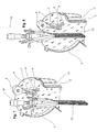
- the oscillating levers can be joined together by a frame forming a support which, on its higher end, terminates in a fork shape for the assembly of the shaft on which the wringing roller idles.
- the box structure of the wringing tool consists of: the front wall which is provided of seats properly shaped for the embossed assembly of the whole box structure so that the lower opening can rise above a basin below: the side walls which contribute to support the kinematic mechanisms for the moving of the pressure roller; the wall opposed to the front bearing wall in curvilinear shape which constitutes the contrast surface where the mops and/or the fringes strips inserted are wrung by the pressure roller.
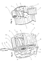
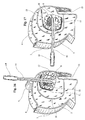
- the oscillating levers supporting the roller are integral with a shaft supported by the side walls; this shaft fits at least with one gear placed outside the aforesaid walls.
- the gear fitted on the shaft which is integral with the roller's oscillating levers is moved by an inner toothing gear fitted on the shaft moved by the control hand lever placed outwards.
- Two helical springs are fixed with one end on the side walls and with the other end on the outside periphery of the inner toothing gear and the same springs bring the kinematic mechanisms system from the end position of the wringing operation to the rest position of the beginning phase.
- the shaft, which the operator roller idles on, is stopped in correspondence to the seats placed on the oscillating levers' ends by screws applied with their heads on the aforesaid levers' ends; they engage it inside proper niches made on its outside surface having a radial placing. This fact establishes the easiness and the functionality of the roller assembly and disassembly (and also of its replacement) by working on the screws engaged on the niches on the ends of the shaft which the roller idles on.
- the higher opening of the wringing tool's box structure is marked with 1;
- the front wall is marked with 2 and it is equipped with the brackets 13; it carries out the proper seats for the embossed support of the whole box structure so that the lower opening can rise above a basin below;
- the wall (opposed to the front bearing wall 2) with a curvilinear shape which constitutes the contrast surface is marked with 3 ; here the mops 12 are inserted and are wrung by the pressure roller 6;
- the side walls which contribute to support the kinematic mechanisms 8, 9 for the moving of the pressure roller are marked with 4 and 5;
- the oscillating levers are marked with 7; they are integral with the shaft 8 and support the pressure roller 6 at its ends;
- the shaft assembled on the side wall 5 is marked with 9 (the side wall 4 can also contribute to the support of the shaft);
- on the side wall 5 is fitted the inner toothing gear 17 and the control hand lever 15 is integrally applied with its end;
- the knob applied on the lever's 15 free end
Applications Claiming Priority (2)
| Application Number | Priority Date | Filing Date | Title |
|---|---|---|---|
| ITPD010038 | 2001-02-20 | ||
| ITPD20010038 ITPD20010038A1 (it) | 2000-09-08 | 2001-02-20 | Strizzatore per mop |
Publications (3)
| Publication Number | Publication Date |
|---|---|
| EP1232719A2 true EP1232719A2 (de) | 2002-08-21 |
| EP1232719A3 EP1232719A3 (de) | 2005-02-16 |
| EP1232719B1 EP1232719B1 (de) | 2007-03-28 |
Family
ID=11452218
Family Applications (1)
| Application Number | Title | Priority Date | Filing Date |
|---|---|---|---|
| EP02001480A Expired - Lifetime EP1232719B1 (de) | 2001-02-20 | 2002-01-22 | Auswringvorrichtung für Wischgerät |
Country Status (5)
| Country | Link |
|---|---|
| US (1) | US6662401B2 (de) |
| EP (1) | EP1232719B1 (de) |
| AT (1) | ATE357872T1 (de) |
| DE (1) | DE60219089T2 (de) |
| ES (1) | ES2284734T3 (de) |
Cited By (3)
| Publication number | Priority date | Publication date | Assignee | Title |
|---|---|---|---|---|
| GB2372437B (en) * | 2001-02-24 | 2004-11-24 | Scot Young Res Ltd | Improvements in or relating to a mop wringer |
| DE102004038244A1 (de) * | 2004-08-05 | 2006-02-23 | Leifheit Ag | Wischtuchpresse |
| CN105496330A (zh) * | 2015-12-31 | 2016-04-20 | 周铭忠 | 一种高效挤水的地拖桶 |
Families Citing this family (8)
| Publication number | Priority date | Publication date | Assignee | Title |
|---|---|---|---|---|
| US7513956B2 (en) | 2004-09-16 | 2009-04-07 | Filmop S.R.L. | Top-down floor cleaning system |
| US8381351B2 (en) * | 2009-01-08 | 2013-02-26 | Shop-Vac | Mop bucket |
| US8505147B2 (en) * | 2009-10-30 | 2013-08-13 | Rubbermaid Commercial Products, Llc | Flat mop |
| US8567087B2 (en) * | 2009-10-30 | 2013-10-29 | Rubbermaid Commercial Products, Llc | Mop wringer |
| US8938848B2 (en) * | 2009-10-30 | 2015-01-27 | Rubbermaid Commerical Products, Llc | Mop agitator |
| US8393047B2 (en) | 2009-10-30 | 2013-03-12 | Rubermaid Commercial Products, LLC | Mop bucket |
| US9009907B2 (en) | 2010-11-08 | 2015-04-21 | Rubbermaid Commercial Products, Llc | Flat mop frame |
| US9474429B2 (en) | 2013-03-15 | 2016-10-25 | Rubbermaid Commercial Products, Llc | Clean water mopping system |
Citations (5)
| Publication number | Priority date | Publication date | Assignee | Title |
|---|---|---|---|---|
| US1922981A (en) * | 1931-12-22 | 1933-08-15 | Arthur Charles Pearce | Bucket or like receptacle |
| US3441973A (en) * | 1967-09-19 | 1969-05-06 | Albert Turk | Mop wringer with gear driven rolls |
| US4852207A (en) * | 1988-02-18 | 1989-08-01 | Izumi Yamane | Mop squeezer |
| EP0480327A1 (de) * | 1990-10-10 | 1992-04-15 | Vdm S.R.L. | Auswringvorrichtung für einen Mop |
| US5274877A (en) * | 1992-09-21 | 1994-01-04 | Worldwide Integrated Resources, Inc. | Semi-automatic mop wringer |
Family Cites Families (1)
| Publication number | Priority date | Publication date | Assignee | Title |
|---|---|---|---|---|
| IT230580Y1 (it) * | 1993-12-22 | 1999-06-07 | V D M Srl | Dispositivo per la raccolta del liquido sporco di lavaggio e per il contenimento del liquido di bagnatura di uno straccio o simile, per il |
-
2002
- 2002-01-22 DE DE60219089T patent/DE60219089T2/de not_active Expired - Lifetime
- 2002-01-22 ES ES02001480T patent/ES2284734T3/es not_active Expired - Lifetime
- 2002-01-22 EP EP02001480A patent/EP1232719B1/de not_active Expired - Lifetime
- 2002-01-22 AT AT02001480T patent/ATE357872T1/de not_active IP Right Cessation
- 2002-01-29 US US10/060,555 patent/US6662401B2/en not_active Expired - Lifetime
Patent Citations (5)
| Publication number | Priority date | Publication date | Assignee | Title |
|---|---|---|---|---|
| US1922981A (en) * | 1931-12-22 | 1933-08-15 | Arthur Charles Pearce | Bucket or like receptacle |
| US3441973A (en) * | 1967-09-19 | 1969-05-06 | Albert Turk | Mop wringer with gear driven rolls |
| US4852207A (en) * | 1988-02-18 | 1989-08-01 | Izumi Yamane | Mop squeezer |
| EP0480327A1 (de) * | 1990-10-10 | 1992-04-15 | Vdm S.R.L. | Auswringvorrichtung für einen Mop |
| US5274877A (en) * | 1992-09-21 | 1994-01-04 | Worldwide Integrated Resources, Inc. | Semi-automatic mop wringer |
Cited By (6)
| Publication number | Priority date | Publication date | Assignee | Title |
|---|---|---|---|---|
| GB2372437B (en) * | 2001-02-24 | 2004-11-24 | Scot Young Res Ltd | Improvements in or relating to a mop wringer |
| US7383604B2 (en) | 2001-02-24 | 2008-06-10 | Scot Young | Mop wringer |
| DE102004038244A1 (de) * | 2004-08-05 | 2006-02-23 | Leifheit Ag | Wischtuchpresse |
| DE102004038244B4 (de) * | 2004-08-05 | 2012-02-16 | Leifheit Ag | Wischtuchpresse |
| CN105496330A (zh) * | 2015-12-31 | 2016-04-20 | 周铭忠 | 一种高效挤水的地拖桶 |
| CN105496330B (zh) * | 2015-12-31 | 2018-02-23 | 周铭忠 | 一种高效挤水的地拖桶 |
Also Published As
| Publication number | Publication date |
|---|---|
| ATE357872T1 (de) | 2007-04-15 |
| ES2284734T3 (es) | 2007-11-16 |
| EP1232719A3 (de) | 2005-02-16 |
| EP1232719B1 (de) | 2007-03-28 |
| DE60219089D1 (de) | 2007-05-10 |
| US6662401B2 (en) | 2003-12-16 |
| US20020112310A1 (en) | 2002-08-22 |
| DE60219089T2 (de) | 2007-12-06 |
Similar Documents
| Publication | Publication Date | Title |
|---|---|---|
| EP1232719B1 (de) | Auswringvorrichtung für Wischgerät | |
| JP6684351B2 (ja) | フラットモップの洗浄及び絞り脱水用モップバケツ | |
| US8978191B2 (en) | Mop structure | |
| CN108814473A (zh) | 平板拖把的使用方法 | |
| JP2003265384A (ja) | 電動床面作業機 | |
| CN111214190A (zh) | 冲洗式净污分离电动拖把清洁工具 | |
| US20070295219A1 (en) | Brewed-Beverage Vending Machine Provided With Means for Cleaning the Brewing Filter | |
| CN112547728A (zh) | 一种药剂科用取样杯清洗设备 | |
| CN201664285U (zh) | 具有自动清洗拖布功能的脱水桶 | |
| CN213665092U (zh) | 拖地装置和具有其的扫地机器人 | |
| IT9021693A1 (it) | Dispositivo per la strizzatura in particolare di strisce a frange per la pulizia di pavimenti | |
| KR20140033983A (ko) | 안정하게 탈부착되는 고무 블레이드를 구비한 유리창 청소기구 | |
| CN213271539U (zh) | 防堵的水利工程用水利管道 | |
| CN211933945U (zh) | 冲洗式净污分离电动拖把清洁工具 | |
| CN114468903A (zh) | 往复式板拖清洁刮干装置及净污分离板拖清洁桶 | |
| CN210277095U (zh) | 拖把擦拭物挤水装置和拖把清洁桶 | |
| CN217365690U (zh) | 一种拖地装置及清洁机器人 | |
| CN108937734B (zh) | 一种智能扫地机器人 | |
| CN110090825A (zh) | 一种光伏建筑模块装置 | |
| CN211749396U (zh) | 一种拖把挤水结构、具有挤水结构的拖把桶及清洁工具 | |
| CN214017445U (zh) | 一种拖把桶及清洁工具套件 | |
| CN109820458A (zh) | 平板拖把挤水使用方法及其平板拖把清洁工具 | |
| CN110786793B (zh) | 一种手压式旋转拖把 | |
| CN218870198U (zh) | 一种拧水省力的拖把 | |
| CN218852636U (zh) | 一种推拉拧水的拖把 |
Legal Events
| Date | Code | Title | Description |
|---|---|---|---|
| PUAI | Public reference made under article 153(3) epc to a published international application that has entered the european phase |
Free format text: ORIGINAL CODE: 0009012 |
|
| AK | Designated contracting states |
Kind code of ref document: A2 Designated state(s): AT BE CH CY DE DK ES FI FR GB GR IE IT LI LU MC NL PT SE TR |
|
| AX | Request for extension of the european patent |
Free format text: AL;LT;LV;MK;RO;SI |
|
| PUAL | Search report despatched |
Free format text: ORIGINAL CODE: 0009013 |
|
| AK | Designated contracting states |
Kind code of ref document: A3 Designated state(s): AT BE CH CY DE DK ES FI FR GB GR IE IT LI LU MC NL PT SE TR |
|
| AX | Request for extension of the european patent |
Extension state: AL LT LV MK RO SI |
|
| 17P | Request for examination filed |
Effective date: 20050413 |
|
| AKX | Designation fees paid |
Designated state(s): AT BE CH CY DE DK ES FI FR GB GR IE IT LI LU MC NL PT SE TR |
|
| DAX | Request for extension of the european patent (deleted) | ||
| GRAP | Despatch of communication of intention to grant a patent |
Free format text: ORIGINAL CODE: EPIDOSNIGR1 |
|
| GRAS | Grant fee paid |
Free format text: ORIGINAL CODE: EPIDOSNIGR3 |
|
| GRAA | (expected) grant |
Free format text: ORIGINAL CODE: 0009210 |
|
| AK | Designated contracting states |
Kind code of ref document: B1 Designated state(s): AT BE CH CY DE DK ES FI FR GB GR IE IT LI LU MC NL PT SE TR |
|
| PG25 | Lapsed in a contracting state [announced via postgrant information from national office to epo] |
Ref country code: NL Free format text: LAPSE BECAUSE OF FAILURE TO SUBMIT A TRANSLATION OF THE DESCRIPTION OR TO PAY THE FEE WITHIN THE PRESCRIBED TIME-LIMIT Effective date: 20070328 Ref country code: FI Free format text: LAPSE BECAUSE OF FAILURE TO SUBMIT A TRANSLATION OF THE DESCRIPTION OR TO PAY THE FEE WITHIN THE PRESCRIBED TIME-LIMIT Effective date: 20070328 Ref country code: AT Free format text: LAPSE BECAUSE OF FAILURE TO SUBMIT A TRANSLATION OF THE DESCRIPTION OR TO PAY THE FEE WITHIN THE PRESCRIBED TIME-LIMIT Effective date: 20070328 |
|
| REG | Reference to a national code |
Ref country code: GB Ref legal event code: FG4D |
|
| REG | Reference to a national code |
Ref country code: CH Ref legal event code: EP |
|
| REF | Corresponds to: |
Ref document number: 60219089 Country of ref document: DE Date of ref document: 20070510 Kind code of ref document: P |
|
| REG | Reference to a national code |
Ref country code: IE Ref legal event code: FG4D |
|
| PG25 | Lapsed in a contracting state [announced via postgrant information from national office to epo] |
Ref country code: SE Free format text: LAPSE BECAUSE OF FAILURE TO SUBMIT A TRANSLATION OF THE DESCRIPTION OR TO PAY THE FEE WITHIN THE PRESCRIBED TIME-LIMIT Effective date: 20070628 |
|
| PG25 | Lapsed in a contracting state [announced via postgrant information from national office to epo] |
Ref country code: PT Free format text: LAPSE BECAUSE OF FAILURE TO SUBMIT A TRANSLATION OF THE DESCRIPTION OR TO PAY THE FEE WITHIN THE PRESCRIBED TIME-LIMIT Effective date: 20070828 |
|
| ET | Fr: translation filed | ||
| NLV1 | Nl: lapsed or annulled due to failure to fulfill the requirements of art. 29p and 29m of the patents act | ||
| REG | Reference to a national code |
Ref country code: ES Ref legal event code: FG2A Ref document number: 2284734 Country of ref document: ES Kind code of ref document: T3 |
|
| PG25 | Lapsed in a contracting state [announced via postgrant information from national office to epo] |
Ref country code: DK Free format text: LAPSE BECAUSE OF FAILURE TO SUBMIT A TRANSLATION OF THE DESCRIPTION OR TO PAY THE FEE WITHIN THE PRESCRIBED TIME-LIMIT Effective date: 20070328 |
|
| PLBE | No opposition filed within time limit |
Free format text: ORIGINAL CODE: 0009261 |
|
| STAA | Information on the status of an ep patent application or granted ep patent |
Free format text: STATUS: NO OPPOSITION FILED WITHIN TIME LIMIT |
|
| 26N | No opposition filed |
Effective date: 20080102 |
|
| PG25 | Lapsed in a contracting state [announced via postgrant information from national office to epo] |
Ref country code: GR Free format text: LAPSE BECAUSE OF FAILURE TO SUBMIT A TRANSLATION OF THE DESCRIPTION OR TO PAY THE FEE WITHIN THE PRESCRIBED TIME-LIMIT Effective date: 20070629 |
|
| PG25 | Lapsed in a contracting state [announced via postgrant information from national office to epo] |
Ref country code: MC Free format text: LAPSE BECAUSE OF NON-PAYMENT OF DUE FEES Effective date: 20080131 |
|
| PG25 | Lapsed in a contracting state [announced via postgrant information from national office to epo] |
Ref country code: IE Free format text: LAPSE BECAUSE OF NON-PAYMENT OF DUE FEES Effective date: 20080122 |
|
| PG25 | Lapsed in a contracting state [announced via postgrant information from national office to epo] |
Ref country code: CY Free format text: LAPSE BECAUSE OF FAILURE TO SUBMIT A TRANSLATION OF THE DESCRIPTION OR TO PAY THE FEE WITHIN THE PRESCRIBED TIME-LIMIT Effective date: 20070328 |
|
| PG25 | Lapsed in a contracting state [announced via postgrant information from national office to epo] |
Ref country code: LU Free format text: LAPSE BECAUSE OF NON-PAYMENT OF DUE FEES Effective date: 20080122 |
|
| PG25 | Lapsed in a contracting state [announced via postgrant information from national office to epo] |
Ref country code: TR Free format text: LAPSE BECAUSE OF FAILURE TO SUBMIT A TRANSLATION OF THE DESCRIPTION OR TO PAY THE FEE WITHIN THE PRESCRIBED TIME-LIMIT Effective date: 20070328 |
|
| REG | Reference to a national code |
Ref country code: FR Ref legal event code: PLFP Year of fee payment: 15 |
|
| REG | Reference to a national code |
Ref country code: FR Ref legal event code: PLFP Year of fee payment: 16 |
|
| REG | Reference to a national code |
Ref country code: FR Ref legal event code: PLFP Year of fee payment: 17 |
|
| PGFP | Annual fee paid to national office [announced via postgrant information from national office to epo] |
Ref country code: FR Payment date: 20191224 Year of fee payment: 19 |
|
| PGFP | Annual fee paid to national office [announced via postgrant information from national office to epo] |
Ref country code: CH Payment date: 20191231 Year of fee payment: 19 |
|
| PGFP | Annual fee paid to national office [announced via postgrant information from national office to epo] |
Ref country code: IT Payment date: 20200102 Year of fee payment: 19 Ref country code: DE Payment date: 20191230 Year of fee payment: 19 Ref country code: GB Payment date: 20191224 Year of fee payment: 19 Ref country code: ES Payment date: 20200217 Year of fee payment: 19 |
|
| PGFP | Annual fee paid to national office [announced via postgrant information from national office to epo] |
Ref country code: BE Payment date: 20191230 Year of fee payment: 19 |
|
| REG | Reference to a national code |
Ref country code: DE Ref legal event code: R119 Ref document number: 60219089 Country of ref document: DE |
|
| REG | Reference to a national code |
Ref country code: CH Ref legal event code: PL |
|
| GBPC | Gb: european patent ceased through non-payment of renewal fee |
Effective date: 20210122 |
|
| REG | Reference to a national code |
Ref country code: BE Ref legal event code: MM Effective date: 20210131 |
|
| PG25 | Lapsed in a contracting state [announced via postgrant information from national office to epo] |
Ref country code: FR Free format text: LAPSE BECAUSE OF NON-PAYMENT OF DUE FEES Effective date: 20210131 |
|
| PG25 | Lapsed in a contracting state [announced via postgrant information from national office to epo] |
Ref country code: LI Free format text: LAPSE BECAUSE OF NON-PAYMENT OF DUE FEES Effective date: 20210131 Ref country code: DE Free format text: LAPSE BECAUSE OF NON-PAYMENT OF DUE FEES Effective date: 20210803 Ref country code: CH Free format text: LAPSE BECAUSE OF NON-PAYMENT OF DUE FEES Effective date: 20210131 Ref country code: GB Free format text: LAPSE BECAUSE OF NON-PAYMENT OF DUE FEES Effective date: 20210122 |
|
| REG | Reference to a national code |
Ref country code: ES Ref legal event code: FD2A Effective date: 20220427 |
|
| PG25 | Lapsed in a contracting state [announced via postgrant information from national office to epo] |
Ref country code: IT Free format text: LAPSE BECAUSE OF NON-PAYMENT OF DUE FEES Effective date: 20210122 |
|
| PG25 | Lapsed in a contracting state [announced via postgrant information from national office to epo] |
Ref country code: ES Free format text: LAPSE BECAUSE OF NON-PAYMENT OF DUE FEES Effective date: 20210123 Ref country code: BE Free format text: LAPSE BECAUSE OF NON-PAYMENT OF DUE FEES Effective date: 20210131 |