EP1231703A2 - Unipolar-Maschine - Google Patents
Unipolar-Maschine Download PDFInfo
- Publication number
- EP1231703A2 EP1231703A2 EP02000570A EP02000570A EP1231703A2 EP 1231703 A2 EP1231703 A2 EP 1231703A2 EP 02000570 A EP02000570 A EP 02000570A EP 02000570 A EP02000570 A EP 02000570A EP 1231703 A2 EP1231703 A2 EP 1231703A2
- Authority
- EP
- European Patent Office
- Prior art keywords
- unipolar
- magnet
- machine according
- magnets
- conductors
- Prior art date
- Legal status (The legal status is an assumption and is not a legal conclusion. Google has not performed a legal analysis and makes no representation as to the accuracy of the status listed.)
- Granted
Links
Images
Classifications
-
- H—ELECTRICITY
- H02—GENERATION; CONVERSION OR DISTRIBUTION OF ELECTRIC POWER
- H02K—DYNAMO-ELECTRIC MACHINES
- H02K31/00—Acyclic motors or generators, i.e. DC machines having drum or disc armatures with continuous current collectors
Definitions
- the invention relates to a unipolar machine according to the preamble of Claim 1.
- Electrical machines usually generate currents with changing Polarity or changing voltage. With three-phase or AC machines generate AC voltages while at DC machines convert the pulsating voltage into a pulsating DC voltage is still converted.
- Unipolar machines are also known which use the principle of unipolar induction use. With unipolar induction, an electrical DC voltage generated with the help of a permanent magnet.
- the advantage of a unipolar machine is that there are none in its armature periodically changing EMF is induced, but an EMF of constant direction and height, so that a constant DC voltage is generated.
- Unipolar machines use moving armature conductors, which are always arranged in a field of the same polarity. Are electricity turners therefore unnecessary to generate a DC voltage. The generated EMF is relatively low, so that the armature conductors are usually connected in series, by placing them between two brushes and these via return conductors must be routed around the outside of the machine in series with one another combines. Because of the double number of brushes opposite DC machines have not prevailed over Unipolar machines. Unipolar machines are only for special applications, where only small currents to be generated have been used more frequently.
- a generator with a rotor which has a pair has firmly connected unipolar magnets that extend around their longitudinal axis rotate, being in the cylindrical air gap between the two unipolar magnets a plurality of resting anchor conductors are arranged on which a consumer is connected so that slip rings for electrical Contacting the anchor conductor is not necessary.
- CH 423 957 discloses a generator for generating Direct current, which has superconducting armature conductors.
- the anchor ladder will be not moved here either, but are stationary. Electrical voltages are said to be in the anchor conductor can be induced by a rotating magnetic field, which with Deliver three-phase-fed coils.
- the invention has for its object an improved unipolar machine to specify for the generation of direct current that no wear parts such as For example, has slip rings, but can still be used for high performance is and has a particularly simple structure.
- the solution of the invention is based on a unipolar machine with one coaxially arranged pair of unipolar magnets, in its cylindrical Air gap a series of dormant, parallel to the longitudinal axis of the unipolar magnet pair anchor conductors distributed around the circumference of the air gap are arranged, the ends of a power supply or a Consumers are connected.
- the solution according to the invention is characterized in that only the first Magnet of the pair of unipolar magnets along a common longitudinal axis is rotating and the second magnet is stationary.
- a unipolar magnet pair is used used that is arranged coaxially to each other and of which only one Unipolar magnet along a common longitudinal axis of the unipolar magnet pair rotates.
- the cylindrical air gap are a number of dormant, distributed parallel to the longitudinal axis on the circumference of the air gap Anchor conductor provided.
- the solution according to the invention is therefore based on the surprising one Realization that it is sufficient to use only one of the two unipolar magnets to drive and thus move relative to the anchor conductor to an electrical Generate tension. So far it was assumed that the two of them Magnetic field forming magnetic poles would have to be moved together.
- the unipolar machine according to the invention therefore has a new one, however particularly simple structure, in which either only the inner Unipolar magnet rotates while the outer unipolar magnet is resting, or the inner unipolar magnet rests while the outer unipolar magnet rotates. Wear parts such as slip rings can therefore be dispensed with Usually serve the electrical contacting rotating armature conductors.
- the unipolar machine according to the invention has only one rotating unipolar magnets reduce the rotating mass so that less vibrations occur.
- Such a unipolar machine can particularly advantageous as a generator in wind turbines and as a hub drive be used in vehicles.
- the anchor conductors at their respective ends are connected in parallel with one another via ring-shaped connections, so that the single anchor conductor a stable cylindrical body for the recording of the inner unipolar magnet and are simultaneously connected in parallel, thus high currents with the unipolar machine according to the invention can be generated.
- the armature conductors over return conductors in series on the outside of the unipolar magnet pair are switched, so that with the unipolar machine according to the invention high voltage can be generated.
- the outer, dormant unipolar magnets no compensating EMF in the return conductor induced when the outer unipolar magnet is at rest and only the inner one Unipolar magnet rotates.
- anchor conductors are used as groups are connected in parallel and several groups are connected in series, so that both the voltage and the current strength through the interconnection the anchor conductor can be increased as desired.
- the armature conductors with are coupled to the stationary unipolar magnet. So the outer forms Unipolar magnet with the armature conductors one unit when the inner unipolar magnet rotates, or the inner unipolar magnet forms with the armature conductors one unit when the outer unipolar magnet rotates.
- the armature conductor and the dormant unipolar magnet are potted together so that the armature conductor are mechanically stabilized by the sealing compound and from damage are protected.
- At least one the unipolar magnet is formed from ring-shaped bar magnets.
- a yoke element is made of Dynamo sheet is provided, which is the size of the rear air gap reduced between the unipolar magnet pair, the yoke element at least one opening for the passage of a shaft and electrical Has connecting lines. Losses caused by the rear air gap between the stationary and rotating unipolar magnet, be significantly reduced.
- one of the unipolar magnets consists of a is made of magnetizable material that is only in the magnetic field of the other unipolar magnet is magnetized. So the inner unipolar magnet only from a particularly easy to manufacture cylindrical body or the outer unipolar magnet from one cylindrical jacket-shaped body exist.
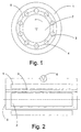
- the invention uses a unipolar pair of magnets with an annular External magnet 1 and an annular inner magnet 2, the two Magnets 1, 2 are unipolar, i.e. they point along their radial Circumferential surface of the same polar magnetic properties.
- 1 is the outer magnet 1 on its inner surface as the north pole and inner magnet 2 formed on its outer surface as a south pole.
- Such unipolar magnets can be formed from known bar magnets by using a plurality of bar magnets with the same direction Pole orientation lying next to each other in a ring, so that they cover the outer surface of a cylindrical base body.
- An air gap is formed between the unipolar magnets 1, 2, in which an Row of annular conductors 3, 4 are located along a connecting line 5 are arranged.
- the outer unipolar magnet 1 is fixed to the conductors 3, 4 connected so that they form a unit.
- the conductors 3, 4 and the outer Unipolar magnet 1 can be encapsulated with a plastic, so one form a compact unit in which the outer unipolar magnet 1 and the Heads 3, 4 are protected by the sealing compound.
- the inner unipolar magnet 2 is used, which is rotatably mounted.
- the inner one the unipolar magnet 2 can consist of a plurality of Bar magnets can be formed or the inner unipolar magnet 2 is a cylindrical body made of a magnetizable material that only after insertion into the outer unipolar magnet 1 by its magnetic field is magnetized.
- the outer unipolar magnet 1 is a tube made of a magnetizable material and the inner unipolar magnet 2 is formed from bar magnets.
- Fig. 2 shows a side view of the basic structure of a unipolar machine according to the invention.
- the annular conductors 3 are arranged, which are connected to one another at their ends an annular connection 5 are coupled to a consumer 6 are connected.
- the armature conductors 3 are parallel to one another interconnected and form together with the outer unipolar magnets 1 a cylindrical body into which the inner unipolar magnet 2 is inserted becomes.
- Anchor conductor 3 can also be connected in series with one another, the return conductor run along the outside of the Unipolar machine so as not to pass through the Magnetic field to be led and cause a reverse EMF there.
- Another alternative is to have multiple anchor conductors in groups in parallel and connect the groups in series.
- a yoke element which is made of dynamo sheet and the unipolar magnet pair 1, 2 to connects a narrow gap that is necessary for one of the two Unipolar magnets 1, 2 can rotate.
- the yoke element points to both End faces of the unipolar machine according to the invention on through the one shaft for the inner unipolar magnet 2 and electrical Cables for the connection of conductors 3, 4 can be carried out.
- the inner unipolar magnet 1 is at rest, while the outer unipolar magnet 2 is rotatably mounted.
- the inner unipolar magnet can 1 and the outer unipolar magnet 2 from a plurality of bar magnets be educated.
- the outer unipolar magnet 2 can be made from a tube be magnetizable material that is made only by the magnetic field of the Bar magnet formed inner unipolar magnet 1 is magnetized, or the outer unipolar magnet 2 is formed from bar magnets, during the inner unipolar magnet 1 a cylindrical body from a is magnetizable material.
Landscapes
- Engineering & Computer Science (AREA)
- Power Engineering (AREA)
- Permanent Field Magnets Of Synchronous Machinery (AREA)
- Permanent Magnet Type Synchronous Machine (AREA)
- Fats And Perfumes (AREA)
- Control Of Motors That Do Not Use Commutators (AREA)
- Control Of Electric Motors In General (AREA)
- Dynamo-Electric Clutches, Dynamo-Electric Brakes (AREA)
- Dc Machiner (AREA)
Abstract
Description
- Fig. 1
- eine Querschnittsansicht des prinzipiellen Aufbaus einer Unipolar-Maschine nach der Erfindung und
- Fig. 2
- eine Seitenansicht eines prinzipiellen Aufbaus einer Unipolar-Maschine.
- 1
- Unipolar-Magnet
- 2
- Unipolar-Magnet
- 3
- Ankerleiter
- 4
- Ankerleiter
- 5
- Verbindung
- 6
- Verbraucher
Claims (9)
- Unipolar-Maschine mit einem koaxial angeordneten Unipolar-Magnetpaar (1, 2), in dessen zylinderförmigen Luftspalt eine Reihe von ruhenden, parallel zur Längsachse des Unipolar-Magnetpaares auf dem Umfang des Luftspalts verteilt verlaufenden Ankerleitern (3, 4) angeordnet sind, deren Enden an eine Stromversorgung bzw. einem Verbraucher angeschlossen sind,
dadurch gekennzeichnet, dass nur der erste Magnet des Unipolar-Magnetpaares (1, 2) entlang einer gemeinsamen Längsachse rotierend ausgebildet ist und der zweite Magnet ruhend ausgebildet ist. - Unipolar-Maschine nach Anspruch 1, dadurch gekennzeichnet, dass die Ankerleiter an ihren jeweiligen Enden über ringförmige Verbindungen (5) miteinander parallel geschaltet sind.
- Unipolar-Maschine nach Anspruch 1, dadurch gekennzeichnet, dass die Ankerleiter (3, 4) über an der Außenseite des Unipolar-Magnetpaars (1, 2) geführte Rückleiter in Reihe geschaltet sind.
- Unipolar-Maschine nach Anspruch 2 und 3, dadurch gekennzeichnet, dass jeweils mehrere Ankerleiter als Gruppen parallel geschaltet sind und mehrere Gruppen in Reihe geschaltet sind.
- Unipolar-Maschine nach einem der vorherigen Ansprüche, dadurch gekennzeichnet, dass die Ankerleiter (3, 4) mit dem ruhenden Unipolar-Magneten (1) gekoppelt sind.
- Unipolar-Maschine nach Anspruch 5, dadurch gekennzeichnet, dass die Ankerleiter (3, 4) und der ruhende Unipolar-Magnet (1) zusammen vergossen sind.
- Unipolar-Maschine nach einem der vorherigen Ansprüche, dadurch gekennzeichnet, dass wenigstens einer der Unipolar-Magneten (1, 2) aus ringförmig angeordneten Stabmagneten gebildet ist.
- Unipolar-Maschine nach einem der vorherigen Ansprüche, dadurch gekennzeichnet, dass ein Jochelement aus Dynamoblech vorgesehen ist, das die Größe des rückseitigen Luftspalts zwischen dem Unipolar-Magnetpaar (1, 2) reduziert, wobei das Jochelement wenigstens eine Öffnung für die Durchführung einer Welle und elektrischer Anschlussleitungen aufweist.
- Unipolar-Maschine nach einem der vorherigen Ansprüche, dadurch gekennzeichnet, dass einer der Unipolar-Magneten (1, 2) aus einem magnetisierbaren Werkstoff gefertigt ist, der erst in dem Magnetfeld des anderen Unipolar-Magneten magnetisiert wird.
Applications Claiming Priority (2)
| Application Number | Priority Date | Filing Date | Title |
|---|---|---|---|
| DE10101785A DE10101785B8 (de) | 2001-01-17 | 2001-01-17 | Unipolar-Maschine |
| DE10101785 | 2001-01-17 |
Publications (3)
| Publication Number | Publication Date |
|---|---|
| EP1231703A2 true EP1231703A2 (de) | 2002-08-14 |
| EP1231703A3 EP1231703A3 (de) | 2003-11-19 |
| EP1231703B1 EP1231703B1 (de) | 2007-01-03 |
Family
ID=7670735
Family Applications (1)
| Application Number | Title | Priority Date | Filing Date |
|---|---|---|---|
| EP02000570A Expired - Lifetime EP1231703B1 (de) | 2001-01-17 | 2002-01-10 | Unipolar-Maschine |
Country Status (4)
| Country | Link |
|---|---|
| EP (1) | EP1231703B1 (de) |
| AT (1) | ATE350803T1 (de) |
| DE (2) | DE10101785B8 (de) |
| ES (1) | ES2280438T3 (de) |
Families Citing this family (4)
| Publication number | Priority date | Publication date | Assignee | Title |
|---|---|---|---|---|
| EP1742329A1 (de) * | 2005-07-08 | 2007-01-10 | Siemens Aktiengesellschaft | Ständerteil eines Turbogenerators und Turbogenerator |
| DE102006060194B4 (de) * | 2006-12-20 | 2011-04-28 | Werth, Vladimir, Dipl.-Ing. | Gleichstromgenerator oder -motor |
| DE102009013660A1 (de) * | 2008-03-11 | 2009-12-10 | Schlüter, Gerd | Homopolare-Maschine |
| DE102016204667A1 (de) * | 2016-03-22 | 2017-09-28 | Bayerische Motoren Werke Aktiengesellschaft | Elektrische Maschine |
Family Cites Families (9)
| Publication number | Priority date | Publication date | Assignee | Title |
|---|---|---|---|---|
| CH423957A (de) * | 1965-08-12 | 1966-11-15 | Bbc Brown Boveri & Cie | Gleichstromgenerator |
| DE1563003A1 (de) * | 1966-07-29 | 1970-01-15 | Soltau Dietrich Carsten | Neuer Generator zur Erzeugung von Gleich- und Wechselstrom |
| FR1586421A (de) * | 1968-08-07 | 1970-02-20 | ||
| DE2823313A1 (de) * | 1978-05-29 | 1979-12-06 | Siemens Ag | Homopolar erregter ein- oder mehrphasiger wechselstromgenerator |
| JPS5899255A (ja) * | 1981-12-09 | 1983-06-13 | Takashi Suzuki | 回転電気機械 |
| DE3509906A1 (de) * | 1984-10-15 | 1986-04-17 | M. Fahrettin Dipl.-Ing. Kadiköy-Istanbul Ergüvenc | Dauermagnetmotor |
| JPS61280752A (ja) * | 1985-06-05 | 1986-12-11 | Oopack Kk | 無刷子直流回転電機 |
| JPH01270759A (ja) * | 1988-04-11 | 1989-10-30 | Daigen Kin | 多相対称単極性無整流子直流電動機 |
| JPH0993996A (ja) * | 1995-09-28 | 1997-04-04 | Yoshiaki Takahashi | 発電電動機 |
-
2001
- 2001-01-17 DE DE10101785A patent/DE10101785B8/de not_active Expired - Fee Related
-
2002
- 2002-01-10 DE DE50209116T patent/DE50209116D1/de not_active Expired - Lifetime
- 2002-01-10 ES ES02000570T patent/ES2280438T3/es not_active Expired - Lifetime
- 2002-01-10 AT AT02000570T patent/ATE350803T1/de not_active IP Right Cessation
- 2002-01-10 EP EP02000570A patent/EP1231703B1/de not_active Expired - Lifetime
Also Published As
| Publication number | Publication date |
|---|---|
| EP1231703A3 (de) | 2003-11-19 |
| DE10101785B8 (de) | 2004-08-05 |
| DE10101785A1 (de) | 2002-07-25 |
| ES2280438T3 (es) | 2007-09-16 |
| EP1231703B1 (de) | 2007-01-03 |
| DE50209116D1 (de) | 2007-02-15 |
| ATE350803T1 (de) | 2007-01-15 |
| DE10101785B4 (de) | 2004-04-29 |
Similar Documents
| Publication | Publication Date | Title |
|---|---|---|
| DE2417818C2 (de) | Elektrische Maschine | |
| DE2445765A1 (de) | Elektrischer generator | |
| EP1362404B1 (de) | Elektrische maschine | |
| DE3737603C2 (de) | ||
| DE2225442A1 (de) | Kollektorloser gleichstrom-motor | |
| DE2800886A1 (de) | Gleichstrommotor | |
| DE3917343A1 (de) | Schleifringloser klauenpol-generator | |
| DE3927454C2 (de) | ||
| DE1230486B (de) | Elektrische Maschine, die mit zwei beiderseits des Rotors angeordneten Magneten versehen ist | |
| DE3933790C2 (de) | Elektrische Maschine mit einem Rotor und einem Stator | |
| DE1940128A1 (de) | Synchrone elektrische Maschine mit einem gleichfelderregten Rotor | |
| EP1231703A2 (de) | Unipolar-Maschine | |
| DE69821041T2 (de) | Modularer elektrischer Motor | |
| DE102020203945A1 (de) | Statorwicklungssystem mit serieller Spulenwicklung | |
| DE102015013662A1 (de) | Elektromotor | |
| CH686159A5 (de) | Buerstenloser motor | |
| DE102018112186A1 (de) | Rotor oder Stator eines Elektromotors | |
| DE1488053B2 (de) | Rotierende elektrische gleichstrommaschine fuer niedrige spannungen und grosse stromstaerken | |
| DE29613756U1 (de) | Generator | |
| CH670535A5 (de) | ||
| DE1638569A1 (de) | Kollektorloser Gleichstrom-Kleinstmotor mit permanentmagneterregtem Laeufer | |
| DE8905353U1 (de) | Synchronmaschine | |
| DE68911905T2 (de) | Elektrischer Motor ohne Stromwenderteile mit in der Richtung der Achse aufgestellten Polen und auf demselben Prinzip basierender magnetischer Motor. | |
| EP0543031A1 (de) | Permanentmagnetmotoren | |
| DE102019208364B4 (de) | Reluktanzmaschine, Antriebseinrichtung und Verfahren zum Betrieb einer Reluktanzmaschine |
Legal Events
| Date | Code | Title | Description |
|---|---|---|---|
| PUAI | Public reference made under article 153(3) epc to a published international application that has entered the european phase |
Free format text: ORIGINAL CODE: 0009012 |
|
| AK | Designated contracting states |
Kind code of ref document: A2 Designated state(s): AT BE CH CY DE DK ES FI FR GB GR IE IT LI LU MC NL PT SE TR |
|
| AX | Request for extension of the european patent |
Free format text: AL;LT;LV;MK;RO;SI |
|
| PUAL | Search report despatched |
Free format text: ORIGINAL CODE: 0009013 |
|
| AK | Designated contracting states |
Kind code of ref document: A3 Designated state(s): AT BE CH CY DE DK ES FI FR GB GR IE IT LI LU MC NL PT SE TR |
|
| AX | Request for extension of the european patent |
Extension state: AL LT LV MK RO SI |
|
| RIC1 | Information provided on ipc code assigned before grant |
Ipc: 7H 02K 31/00 A Ipc: 7H 02K 53/00 B |
|
| RIN1 | Information on inventor provided before grant (corrected) |
Inventor name: LIPSKI, HANS-JUERGEN |
|
| 17P | Request for examination filed |
Effective date: 20040514 |
|
| AKX | Designation fees paid |
Designated state(s): AT BE CH CY DE DK ES FI FR GB GR IE IT LI LU MC NL PT SE TR |
|
| 17Q | First examination report despatched |
Effective date: 20040706 |
|
| GRAP | Despatch of communication of intention to grant a patent |
Free format text: ORIGINAL CODE: EPIDOSNIGR1 |
|
| GRAS | Grant fee paid |
Free format text: ORIGINAL CODE: EPIDOSNIGR3 |
|
| GRAA | (expected) grant |
Free format text: ORIGINAL CODE: 0009210 |
|
| AK | Designated contracting states |
Kind code of ref document: B1 Designated state(s): AT BE CH CY DE DK ES FI FR GB GR IE IT LI LU MC NL PT SE TR |
|
| PG25 | Lapsed in a contracting state [announced via postgrant information from national office to epo] |
Ref country code: NL Free format text: LAPSE BECAUSE OF FAILURE TO SUBMIT A TRANSLATION OF THE DESCRIPTION OR TO PAY THE FEE WITHIN THE PRESCRIBED TIME-LIMIT Effective date: 20070103 Ref country code: DK Free format text: LAPSE BECAUSE OF FAILURE TO SUBMIT A TRANSLATION OF THE DESCRIPTION OR TO PAY THE FEE WITHIN THE PRESCRIBED TIME-LIMIT Effective date: 20070103 Ref country code: FI Free format text: LAPSE BECAUSE OF FAILURE TO SUBMIT A TRANSLATION OF THE DESCRIPTION OR TO PAY THE FEE WITHIN THE PRESCRIBED TIME-LIMIT Effective date: 20070103 Ref country code: IE Free format text: LAPSE BECAUSE OF FAILURE TO SUBMIT A TRANSLATION OF THE DESCRIPTION OR TO PAY THE FEE WITHIN THE PRESCRIBED TIME-LIMIT Effective date: 20070103 |
|
| REG | Reference to a national code |
Ref country code: GB Ref legal event code: FG4D Free format text: NOT ENGLISH |
|
| PG25 | Lapsed in a contracting state [announced via postgrant information from national office to epo] |
Ref country code: LI Free format text: LAPSE BECAUSE OF NON-PAYMENT OF DUE FEES Effective date: 20070131 Ref country code: CH Free format text: LAPSE BECAUSE OF NON-PAYMENT OF DUE FEES Effective date: 20070131 Ref country code: MC Free format text: LAPSE BECAUSE OF NON-PAYMENT OF DUE FEES Effective date: 20070131 |
|
| REF | Corresponds to: |
Ref document number: 50209116 Country of ref document: DE Date of ref document: 20070215 Kind code of ref document: P |
|
| REG | Reference to a national code |
Ref country code: IE Ref legal event code: FG4D Free format text: LANGUAGE OF EP DOCUMENT: GERMAN |
|
| PG25 | Lapsed in a contracting state [announced via postgrant information from national office to epo] |
Ref country code: SE Free format text: LAPSE BECAUSE OF FAILURE TO SUBMIT A TRANSLATION OF THE DESCRIPTION OR TO PAY THE FEE WITHIN THE PRESCRIBED TIME-LIMIT Effective date: 20070403 |
|
| GBT | Gb: translation of ep patent filed (gb section 77(6)(a)/1977) |
Effective date: 20070404 |
|
| PG25 | Lapsed in a contracting state [announced via postgrant information from national office to epo] |
Ref country code: PT Free format text: LAPSE BECAUSE OF FAILURE TO SUBMIT A TRANSLATION OF THE DESCRIPTION OR TO PAY THE FEE WITHIN THE PRESCRIBED TIME-LIMIT Effective date: 20070604 |
|
| NLV1 | Nl: lapsed or annulled due to failure to fulfill the requirements of art. 29p and 29m of the patents act | ||
| ET | Fr: translation filed | ||
| REG | Reference to a national code |
Ref country code: IE Ref legal event code: FD4D |
|
| REG | Reference to a national code |
Ref country code: CH Ref legal event code: PL |
|
| REG | Reference to a national code |
Ref country code: ES Ref legal event code: FG2A Ref document number: 2280438 Country of ref document: ES Kind code of ref document: T3 |
|
| PLBE | No opposition filed within time limit |
Free format text: ORIGINAL CODE: 0009261 |
|
| STAA | Information on the status of an ep patent application or granted ep patent |
Free format text: STATUS: NO OPPOSITION FILED WITHIN TIME LIMIT |
|
| 26N | No opposition filed |
Effective date: 20071005 |
|
| BERE | Be: lapsed |
Owner name: LIPSKI, HANS-JURGEN Effective date: 20070131 Owner name: SCHLUTER, GERD Effective date: 20070131 |
|
| PG25 | Lapsed in a contracting state [announced via postgrant information from national office to epo] |
Ref country code: BE Free format text: LAPSE BECAUSE OF NON-PAYMENT OF DUE FEES Effective date: 20070131 |
|
| PG25 | Lapsed in a contracting state [announced via postgrant information from national office to epo] |
Ref country code: GR Free format text: LAPSE BECAUSE OF FAILURE TO SUBMIT A TRANSLATION OF THE DESCRIPTION OR TO PAY THE FEE WITHIN THE PRESCRIBED TIME-LIMIT Effective date: 20070404 |
|
| PG25 | Lapsed in a contracting state [announced via postgrant information from national office to epo] |
Ref country code: AT Free format text: LAPSE BECAUSE OF NON-PAYMENT OF DUE FEES Effective date: 20070110 |
|
| PGFP | Annual fee paid to national office [announced via postgrant information from national office to epo] |
Ref country code: TR Payment date: 20080109 Year of fee payment: 7 |
|
| PG25 | Lapsed in a contracting state [announced via postgrant information from national office to epo] |
Ref country code: CY Free format text: LAPSE BECAUSE OF FAILURE TO SUBMIT A TRANSLATION OF THE DESCRIPTION OR TO PAY THE FEE WITHIN THE PRESCRIBED TIME-LIMIT Effective date: 20070103 |
|
| PG25 | Lapsed in a contracting state [announced via postgrant information from national office to epo] |
Ref country code: LU Free format text: LAPSE BECAUSE OF NON-PAYMENT OF DUE FEES Effective date: 20070110 |
|
| PGFP | Annual fee paid to national office [announced via postgrant information from national office to epo] |
Ref country code: FR Payment date: 20110317 Year of fee payment: 10 Ref country code: IT Payment date: 20110228 Year of fee payment: 10 |
|
| PGFP | Annual fee paid to national office [announced via postgrant information from national office to epo] |
Ref country code: GB Payment date: 20110228 Year of fee payment: 10 Ref country code: ES Payment date: 20110228 Year of fee payment: 10 |
|
| GBPC | Gb: european patent ceased through non-payment of renewal fee |
Effective date: 20120110 |
|
| REG | Reference to a national code |
Ref country code: FR Ref legal event code: ST Effective date: 20120928 |
|
| PG25 | Lapsed in a contracting state [announced via postgrant information from national office to epo] |
Ref country code: GB Free format text: LAPSE BECAUSE OF NON-PAYMENT OF DUE FEES Effective date: 20120110 |
|
| PG25 | Lapsed in a contracting state [announced via postgrant information from national office to epo] |
Ref country code: IT Free format text: LAPSE BECAUSE OF NON-PAYMENT OF DUE FEES Effective date: 20120110 |
|
| PG25 | Lapsed in a contracting state [announced via postgrant information from national office to epo] |
Ref country code: FR Free format text: LAPSE BECAUSE OF NON-PAYMENT OF DUE FEES Effective date: 20120131 |
|
| PG25 | Lapsed in a contracting state [announced via postgrant information from national office to epo] |
Ref country code: TR Free format text: LAPSE BECAUSE OF NON-PAYMENT OF DUE FEES Effective date: 20090110 |
|
| PGFP | Annual fee paid to national office [announced via postgrant information from national office to epo] |
Ref country code: DE Payment date: 20130227 Year of fee payment: 12 |
|
| REG | Reference to a national code |
Ref country code: ES Ref legal event code: FD2A Effective date: 20130705 |
|
| PG25 | Lapsed in a contracting state [announced via postgrant information from national office to epo] |
Ref country code: ES Free format text: LAPSE BECAUSE OF NON-PAYMENT OF DUE FEES Effective date: 20120111 |
|
| REG | Reference to a national code |
Ref country code: DE Ref legal event code: R119 Ref document number: 50209116 Country of ref document: DE |
|
| PG25 | Lapsed in a contracting state [announced via postgrant information from national office to epo] |
Ref country code: DE Free format text: LAPSE BECAUSE OF NON-PAYMENT OF DUE FEES Effective date: 20140801 |
|
| REG | Reference to a national code |
Ref country code: DE Ref legal event code: R119 Ref document number: 50209116 Country of ref document: DE Effective date: 20140801 |