EP1231474A2 - Verfahren und Vorrichtung zum Lokalisieren von möglicherweise fehlerhaften Stiften in einem Prüfadapter sowie Stiftziehwerkzeug - Google Patents
Verfahren und Vorrichtung zum Lokalisieren von möglicherweise fehlerhaften Stiften in einem Prüfadapter sowie Stiftziehwerkzeug Download PDFInfo
- Publication number
- EP1231474A2 EP1231474A2 EP02450025A EP02450025A EP1231474A2 EP 1231474 A2 EP1231474 A2 EP 1231474A2 EP 02450025 A EP02450025 A EP 02450025A EP 02450025 A EP02450025 A EP 02450025A EP 1231474 A2 EP1231474 A2 EP 1231474A2
- Authority
- EP
- European Patent Office
- Prior art keywords
- pin
- test adapter
- pen
- sleeve
- drawing tool
- Prior art date
- Legal status (The legal status is an assumption and is not a legal conclusion. Google has not performed a legal analysis and makes no representation as to the accuracy of the status listed.)
- Granted
Links
Images



Classifications
-
- G—PHYSICS
- G01—MEASURING; TESTING
- G01R—MEASURING ELECTRIC VARIABLES; MEASURING MAGNETIC VARIABLES
- G01R3/00—Apparatus or processes specially adapted for the manufacture or maintenance of measuring instruments, e.g. of probe tips
-
- G—PHYSICS
- G01—MEASURING; TESTING
- G01R—MEASURING ELECTRIC VARIABLES; MEASURING MAGNETIC VARIABLES
- G01R35/00—Testing or calibrating of apparatus covered by the other groups of this subclass
-
- G—PHYSICS
- G01—MEASURING; TESTING
- G01R—MEASURING ELECTRIC VARIABLES; MEASURING MAGNETIC VARIABLES
- G01R1/00—Details of instruments or arrangements of the types included in groups G01R5/00 - G01R13/00 and G01R31/00
- G01R1/02—General constructional details
- G01R1/06—Measuring leads; Measuring probes
- G01R1/067—Measuring probes
- G01R1/073—Multiple probes
- G01R1/07307—Multiple probes with individual probe elements, e.g. needles, cantilever beams or bump contacts, fixed in relation to each other, e.g. bed of nails fixture or probe card
- G01R1/07314—Multiple probes with individual probe elements, e.g. needles, cantilever beams or bump contacts, fixed in relation to each other, e.g. bed of nails fixture or probe card the body of the probe being perpendicular to test object, e.g. bed of nails or probe with bump contacts on a rigid support
Definitions
- the invention relates to a method and an apparatus for locating possibly faulty pens in one Test adapter that is used to test printed circuit boards in a tester is used.
- the invention relates to a pen tool for Pull a pin located in this way from a test adapter.
- Test adapters for testing printed circuit boards are known, cf. for example EP 994 359 A2. It is also known that Equip test adapter with pins or needles that are used during testing electrical circuit boards in a tester Establish test points on the respective printed circuit board. Will in the course this check of the printed circuit board an error related with the establishment of contact and the resultant Circuit behavior determined, it must be checked whether there is actually a fault in the circuit board, or whether the corresponding pin of the test adapter is not faulty. It is difficult and time-consuming to find the respective test pin to look in the equipped test adapter, whereby it comes to a machine standstill comes, which takes accordingly long and too Delays in testing the printed circuit boards.
- the respective test pin provided it has been determined in its position can be, even with complex manipulations To deceive. It should be borne in mind that the pens, for example at intervals of less than 2 mm or - on the contacting side - can even be as small as approx. 0.5 mm. So it is understandable that with such a narrow pin arrangement Finding a pen and changing the pens is extraordinary is difficult.
- the inventive method of the type mentioned is characterized by the coordinates given by the tester of fault locations of an X-Y control of a drive device are supplied with a corresponding X-Y relative movement between a light transmitter and the test adapter brought about, with the help of the so in through the coordinates given position in alignment with the respective pin Light transmitter the pen is indicated by lighting.
- the device according to the invention is correspondingly characterized by a support for the test adapter with which a drive device for a light source is connected, which is an X-Y controller with coordinate data supply unit assigned.
- the invention takes advantage of the fact that when testing Printed circuit boards in the event of the discovery of a fault which in addition to the printed circuit board also assigned to the pin in the test adapter the coordinates of the fault location in the tester could be known are.
- a tester usually shows the faulty one Place on the circuit board - and accordingly, of course also the corresponding position on the test adapter - in coordinates and exactly this coordinate information can subsequently - at Disconnect the test adapter from the circuit board - to display the pin in the respective position in the test adapter be used.
- the coordinates of the Defect the X-Y coordinates for a light transmitter (preferably receive a laser pointer), and this light transmitter will according to the X or Y coordinates in the respective position controlled relative to the test adapter so that after moving in this position with a narrow beam of light the pen on that Illuminated spot that corresponds to the identified fault position.
- the pen indicated by lighting can then be removed from the Test adapter are pulled so that it can be checked or, in In case of a defective pen, replace it with another pen becomes. This will save a considerable amount of time achieved, and moreover, the adapter plates and Protected adapter frame.
- test adapter - as is preferably provided - to locate the respective pin from the printed circuit board tester removed and in a separate device that the aforementioned Has support for a test adapter is arranged.
- the test adapter - not only the pen you are looking for can help of the X-Y controlled light transmitter can be found quickly and visually appear, it is also the pen then without any disabilities freely accessible through other components so that it can be quickly pulled can be.
- the drive device two linear drives arranged at right angles to one another, in particular Spindle drives with stepper motors, contains that to the X-Y control are connected. If necessary, the linear drives but also realized with chains or ropes (without stretching) become.
- test adapter For an exact alignment of the test adapter to the light transmitter device it is beneficial if the edition System and / or centering elements for automatic alignment and Centering the test adapter. Because the test adapter itself furthermore have different sizes and in different positions (e.g. bottom side up) and alignments (left / right swapped) it can also be attached to the pad favorable if the edition has at least one sensor for detecting the Adapter format and / or the location and / or orientation of the Adapters is assigned relative to the edition.
- a particularly sharp and bright point of light on the head to bring about the respective pen it has as before mentioned as found to be advantageous when the light source is formed by a laser pointer.
- the X-Y control can be supplied with its own keyboard be provided with the X-Y controller for the light transmitter drive device connected is. To such a separate manual input can also be omitted that the X-Y coordinate data of the X-Y control directly via a computer, namely the computer that the printed circuit board tester is assigned. Furthermore, the coordinate data but also entered using a barcode scanner become.
- the pen-drawing tool according to the invention is characterized by a simple construction with a sleeve that has a handle part and has internal dimensions adapted to the inside of the pin head, to grasp the pin head frictionally, so that the Can be pulled out of the test adapter.
- the sleeve is preferably in one piece.
- the sleeve made of a metal, e.g. Titanium or steel.
- the handle part compared to the rest of the sleeve has a larger external dimension. It is also advantageous here if there is a plastic or rubber pad on the handle is applied.
- a Error when testing a circuit board using a Pen test adapter proceeded in such a way that the test adapter is off taken from the circuit board tester and in the finder device is placed on the edition provided there.
- All steps in the Pen searches are performed outside and separately from the circuit board tester.
- the coordinates provided by the tester are, for example via the input keyboard, via the scanner or also automatically on command from a computer belonging to the tester entered and the X-Y controller for the light source drive device fed.
- the light transmitter is then moved to the corresponding X-Y location moved by driving the two drive devices or activated, and the light transmitter marks the pin located at this point with a sharp point of light.
- the pen can now be removed using the pen tool or be exchanged. Then the test adapter can be put back into the Printed circuit board testers are used.
- Test fields 1, 2 are an upper and lower test field, respectively a testing machine, also called a tester.
- a testing machine also called a tester.
- Test fields 1, 2 are used for checking a printed circuit board provided on both sides with conductor tracks 3
- Test fields 1, 2 have contact zones 4 which end with one end of Pins 5 come into contact, the other ends of the conductor tracks 6 contact the printed circuit board 3 at the desired points.
- To align metal surfaces of the printed circuit board 3 is a top Test adapter 7 and an underside test adapter 8 are provided.
- Each test adapter 7, 8 consists, for example, of several by spacers 9 spaced plates, e.g. 10, 11 to align the pins 5 in the desired manner.
- the pins On the pin exit side, adjacent to the PCB 3, the pins at intervals of just 0.4 mm available.
- the pin positions are at greater intervals (in practice it must PCB not always all positions with one Pen)), in a predetermined grid, like this will be explained below with reference to FIG. 3A.
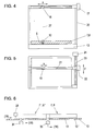
- test adapter 7 is shown schematically in FIG. 2 or 8 on a support 13 of a localization device illustrated by pins 5. As can be seen, the respective Test adapter 7 or 8 attached to the pad 13 such that the pins 5 with the heads 12 upwards, away from the support 13, are directed.
- FIG. 3 schematically illustrates how above one Test adapter 7 or 8, with on its top according to a predetermined grid 14 arranged pin heads 12 (see also Fig. 3A), in one with the support 13 not shown in FIG. 3 a drive for the test adapter 7 or 8 permanently connected frame and control device 17 for an X-Y movement of an as Light transmitter provided laser pointer 16 is attached.
- the X-Y control 17 are via a computer unit 18, the coordinates of the desired pin 5 are fed or entered, corresponding control signals for those not shown in FIG. 3 actual drive device for the laser pointer 16 fed.
- the coordinate data can be from the tester 1, 2 of the computer unit 18 can be fed directly, or else it can Coordinate data manually or using a barcode can be entered.
- the laser pointer 16 is in the X direction along a cross-section e.g. C-shaped guide rail 21 (s. Fig. 7) driven by a stepper motor, which in turn along a corresponding Y-guide rail A stepper motor 24 can be driven (see FIG. 5) the X guide rail 21 together with the laser pointer 16 in the Y direction is moved together with the stepper motor 22.
- a cross-section e.g. C-shaped guide rail 21 (s. Fig. 7) driven by a stepper motor, which in turn along a corresponding Y-guide rail
- a stepper motor 24 can be driven (see FIG. 5) the X guide rail 21 together with the laser pointer 16 in the Y direction is moved together with the stepper motor 22.
- FIG. 7 is a bearing slide within the guide rail 21 25 slidably mounted, and this bearing slide 25th carries a mounting plate 26 to which the laser pointer 16 is attached is.
- FIG. 7 also illustrates how the laser pointer 16 the head 12 of a pin 5 in a test adapter 7 or 8 with a light beam 27 illuminated.
- Slip contacts are used to power the laser pointer 16 28, 29 and busbars 30, 31 along the guide rail 21 provided.
- a very schematic indicated driver 32 can be seen, here it for example around a spindle nut of a spindle drive, such as well known per se, or also about a driver, connected with a cable can act.
- a spindle or a rope is indicated in FIG. 7 at 32 '.
- stepper motors 22, 24 mentioned X-Y control 17 or drive device (21 to 25) for Realizes the laser pointer 16, as mentioned by the computer unit 18 the corresponding control signals to the stepper motors 22, 24 are applied to the laser pointer 16 in the each given X-Y position, to illuminate the possibly defective pin 5 or its head 12 to move.
- table-shaped Pad 13 assigned a plurality of sensors 33, 34, 35, and pad 13 can be sized to accommodate test adapters in different sizes, with system and / or centering elements 13 'can be provided.
- sensors 33, 35 can therefore the given adapter format can be recognized.
- sensor 34 it can also be recognized whether an upper-side test adapter 7 in its normal orientation or a test adapter 8 on the underside, turned by 180 ° is present. In the latter case, for example, in the shown Embodiment mirrored the coordinates in the Y direction before the X-Y control for moving the laser pointer 16 is controlled in the desired position.
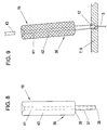
- This is the pen drawing tool 19 forming sleeve 36 is, for example, in one piece from metal, especially titanium or steel, and it has a front shaft part 37 with a small cross section, in particular in the order of 2 mm outside diameter.
- This Shaft part 37 is conically tapered towards the free tip 38, and at its rear end it goes over a shoulder 39 in a widened handle portion 40.
- Through the entire sleeve 36 extends a bore 41, for example with a Diameter of 1.4 mm.
- the outer diameter at the tip 38 is of the shaft part 37, for example 1.6 mm, so that there results in a wall thickness of 0.1 mm.
- the handle part 40 can have an outer diameter of 6 mm.
- the handle part 40 can further, as illustrated in Figure 9, with a plastic or Rubber pad 42 may be provided to grip and hold by hand.
- the sleeve 36 becomes to pull one - illuminated - pin 5 simply pushed over its head 12, the head 12 being held in the sleeve 36 by friction becomes. This can be done by slightly tilting it the sleeve 36 are reinforced when pulling the pin 5.
Landscapes
- Physics & Mathematics (AREA)
- General Physics & Mathematics (AREA)
- Tests Of Electronic Circuits (AREA)
- Testing Of Short-Circuits, Discontinuities, Leakage, Or Incorrect Line Connections (AREA)
Abstract
Description
Claims (19)
- Verfahren zum Lokalisieren von möglicherweise fehlerhaften Stiften (5) in einem Prüfadapter (7;8), der zum Testen von Leiterplatinen (3) in einen Tester (1;2) eingesetzt wird, dadurch gekennzeichnet, dass vom Tester ausgegebene Koordinaten von Fehlerstellen einer X-Y-Steuerung (17) einer Antriebseinrichtung (21-25) zugeführt werden, die eine entsprechende X-Y-Relativbewegung zwischen einem Lichtsender (16) und dem Prüfadapter (7;8) herbeiführt, wobei mit Hilfe des so in die durch die Koordinaten gegebene Position in Ausrichtung zum jeweiligen Stift (5) gebrachten Lichtsenders (16) der Stift (5) durch Beleuchten angezeigt wird.
- Verfahren nach Anspruch 1, dadurch gekennzeichnet, dass der Prüfadapter (7;8) zum Lokalisieren der Stifte (5) aus dem Leiterplatinen-Tester entfernt wird, um die Stift-Lokalisierung durch Beleuchten vorzunehmen.
- Verfahren nach Anspruch 1 oder 2, dadurch gekennzeichnet, dass der durch das Beleuchten mit dem Lichtsender (16) angezeigte Stift (5) aus dem Prüfadapter (7;8) außerhalb des Leiterplatinen-Testers entfernt und ersetzt wird.
- Vorrichtung zum Lokalisieren von möglicherweise fehlerhaften Stiften in einem Prüfadapter (7;8) , der zum Testen von Leiterplatinen (3) in einen Tester (1;2) eingesetzt wird, gekennzeichnet durch eine Auflage (13) für den Prüfadapter (7;8), mit der eine Antriebseinrichtung (21-25) für einen Lichtsender (16) verbunden ist, welcher eine X-Y-Steuerung (17) mit Koordinatendaten-Zuführeinheit (18) zugeordnet ist.
- Vorrichtung nach Anspruch 4, dadurch gekennzeichnet, dass die Antriebseinrichtung (21-25) zwei zueinander rechtwinkelig angeordnete Linearantriebe enthält, die an die X-Y-Steuerung (17) angeschlossen sind.
- Vorrichtung nach Anspruch 5, dadurch gekennzeichnet, dass die Linearantriebe durch Spindeltriebe mit Schrittmotoren (22, 24) gebildet sind.
- Vorrichtung nach einem der Ansprüche 4 bis 6, dadurch gekennzeichnet, dass die Auflage (13) Anlage- und/oder Zentrierelemente (13') für eine automatische Ausrichtung und Zentrierung des Prüfadapters (7;8) aufweist.
- Vorrichtung nach einem der Ansprüche 4 bis 7, dadurch gekennzeichnet, dass der Auflage (13) zumindest ein Sensor (33, 34, 35) zur Erkennung des Adapter-Formats und/oder der Lage und/oder der Ausrichtung des Prüfadapters (7;8) relativ zur Auflage (13) zugeordnet ist.
- Vorrichtung nach einem der Ansprüche 4 bis 8, dadurch gekennzeichnet, dass der Lichtsender (16) durch einen Laserpointer gebildet ist.
- Vorrichtung nach einem der Ansprüche 4 bis 9, dadurch gekennzeichnet, dass als Koordinatendaten-Zuführeinheit eine eigene Tastatur vorgesehen ist.
- Vorrichtung nach einem der Ansprüche 4 bis 10, dadurch gekennzeichnet, dass als Koordinatendaten-Zuführeinheit ein der X-Y-Steuerung (17) zugeordneter Rechner (18) mit Tastatur vorgesehen ist.
- Vorrichtung nach einem der Ansprüche 4 bis 9, dadurch gekennzeichnet, dass als Koordinatendaten-Zuführeinheit ein Barcode-Scanner vorgesehen ist.
- Stiftziehwerkzeug zum Ziehen eines gemäß dem Verfahren nach einem der Ansprüche 1 bis 3 lokalisierten Stiftes aus einem Prüfadapter (7;8), gekennzeichnet durch eine mit einem Griffteil (40) versehene Hülse (36) mit an den Stiftkopf (12) angepassten Innenabmessungen, um den Stiftkopf (12) reibungsschlüssig zu erfassen.
- Stiftziehwerkzeug nach Anspruch 13, dadurch gekennzeichnet, dass die Hülse (36) außen sich zum freien Ende hin verjüngend ausgeführt ist.
- Stiftziehwerkzeug nach Anspruch 13 oder 14, dadurch gekennzeichnet, dass die Hülse (36) einstückig ist.
- Stiftziehwerkzeug nach einem der Ansprüche 13 bis 15, dadurch gekennzeichnet, dass die Hülse (36) aus einem Metall, z.B. Titan oder Stahl, besteht.
- Stiftziehwerkzeug nach einem der Ansprüche 13 bis 16, dadurch gekennzeichnet, dass der Griffteil (40) gegenüber der übrigen Hülse (36) ein größeres Außenmaß aufweist.
- Stiftziehwerkzeug, nach einem der Ansprüche 13 bis 17, dadurch gekennzeichnet, dass auf dem Griffteil (40) eine Auflage (42) aus Kunststoff oder Gummi aufgebracht ist.
- Stiftziehwerkzeug nach einem der Ansprüche 13 bis 18, dadurch gekennzeichnet, dass die Hülse (36) eine sich über ihre gesamte axiale Länge erstreckende, hindurchgehende Bohrung (41) hat.
Applications Claiming Priority (2)
| Application Number | Priority Date | Filing Date | Title |
|---|---|---|---|
| AT2062001 | 2001-02-12 | ||
| AT0020601A AT412027B (de) | 2001-02-12 | 2001-02-12 | Verfahren und vorrichtung zum lokalisieren von möglicherweise fehlerhaften stiften in einem prüfadapter sowie stiftziehwerkzeug |
Publications (3)
| Publication Number | Publication Date |
|---|---|
| EP1231474A2 true EP1231474A2 (de) | 2002-08-14 |
| EP1231474A3 EP1231474A3 (de) | 2004-08-04 |
| EP1231474B1 EP1231474B1 (de) | 2010-06-02 |
Family
ID=3669607
Family Applications (1)
| Application Number | Title | Priority Date | Filing Date |
|---|---|---|---|
| EP02450025A Expired - Lifetime EP1231474B1 (de) | 2001-02-12 | 2002-02-06 | Verfahren und Vorrichtung zum Lokalisieren von möglicherweise fehlerhaften Stiften in einem Prüfadapter |
Country Status (3)
| Country | Link |
|---|---|
| EP (1) | EP1231474B1 (de) |
| AT (2) | AT412027B (de) |
| DE (1) | DE50214458D1 (de) |
Cited By (6)
| Publication number | Priority date | Publication date | Assignee | Title |
|---|---|---|---|---|
| CN105397711A (zh) * | 2015-12-18 | 2016-03-16 | 东风汽车电子有限公司 | 步进电机组合仪表指针压配设备 |
| CN107855980A (zh) * | 2017-10-10 | 2018-03-30 | 中国空气动力研究与发展中心高速空气动力研究所 | 一种拔销和拉紧装置 |
| CN113043195A (zh) * | 2021-04-30 | 2021-06-29 | 武汉飞恩微电子有限公司 | 一种夹具及调理设备 |
| DE102018202745B4 (de) | 2018-02-23 | 2023-06-01 | Zf Friedrichshafen Ag | Verschleißerkennung bei Kontaktnadeln |
| DE102018202744B4 (de) | 2018-02-23 | 2023-06-01 | Zf Friedrichshafen Ag | Verschleißerkennung bei Kontaktnadeln |
| US12064804B2 (en) | 2022-03-07 | 2024-08-20 | TRUMPF Werkzeugmaschinen SE + Co. KG | Machine handling device and method for handling an electrically conductive sheet-metal workpiece and also machine arrangement for machining sheet metal |
Family Cites Families (20)
| Publication number | Priority date | Publication date | Assignee | Title |
|---|---|---|---|---|
| US3654824A (en) * | 1970-03-11 | 1972-04-11 | Littelfuse Inc | Fuse extractor unit |
| US4050148A (en) * | 1976-06-14 | 1977-09-27 | Cutler-Hammer, Inc. | Snap-in bushing switch removal tool |
| US4052788A (en) * | 1976-07-06 | 1977-10-11 | Cutler-Hammer, Inc. | Tool for removing a snap-in bushing from a mounting panel hole |
| DE3312436A1 (de) * | 1982-10-29 | 1984-05-03 | Feinmetall Gmbh, 7033 Herrenberg | Kontaktiervorrichtung |
| EP0194695A1 (de) * | 1985-03-15 | 1986-09-17 | Feinmetall Gesellschaft mit beschrÀ¤nkter Haftung | Verfahren und Prüfadapter zum Kontaktieren von Bauelementen für Prüfzwecke |
| US4620366A (en) * | 1985-07-17 | 1986-11-04 | Rca Corporation | Automatic pin extraction apparatus for integrated circuit tube |
| DE3722485A1 (de) * | 1987-07-03 | 1989-01-12 | Deutsche Telephonwerk Kabel | Federnde kontaktnadel und kontaktiereinrichtung |
| EP0331163A1 (de) * | 1988-03-04 | 1989-09-06 | Manfred Prokopp | Kontaktiervorrichtung für Prüfvorrichtungen zum Prüfen von Leiterplatten oder dgl. |
| US4963822A (en) * | 1988-06-01 | 1990-10-16 | Manfred Prokopp | Method of testing circuit boards and the like |
| JPH0210271A (ja) * | 1988-06-29 | 1990-01-16 | Fujitsu General Ltd | プリント基板のチェック装置 |
| DE8907245U1 (de) * | 1989-06-14 | 1989-08-10 | Agfa-Gevaert Ag, 5090 Leverkusen | Selbstkontrollierende Prüfvorrichtung für Bauteile |
| US5408189A (en) * | 1990-05-25 | 1995-04-18 | Everett Charles Technologies, Inc. | Test fixture alignment system for printed circuit boards |
| DE4242837A1 (de) * | 1992-12-17 | 1994-06-23 | Siemens Ag | Verfahren und Vorrichtung zum Einpressen von metallischen Elementen in Trägerteile |
| US5537736A (en) * | 1994-11-08 | 1996-07-23 | Higa; Lawrence R. | Tool for removing microchip modules from their sockets |
| NL1004510C2 (nl) * | 1996-11-12 | 1998-05-14 | Charmant Beheer B V | Werkwijze voor het vervaardigen van een test-adapter alsmede test-adapter en een werkwijze voor het testen van printplaten. |
| IT1290345B1 (it) * | 1997-02-18 | 1998-10-22 | Circuit Line Spa | Metodo e dispositivo per la correzione dell'errore di allineamento fra aghi di test e punti di test nella fase di test elettrico di |
| DE19716945C2 (de) * | 1997-04-22 | 1999-07-29 | Siemens Ag | Prüfadapter für elektrische Flachbaugruppen |
| JP3028095B2 (ja) * | 1998-03-04 | 2000-04-04 | 日本電気株式会社 | プロービング装置および方法 |
| DE19847146A1 (de) * | 1998-10-13 | 2000-05-04 | Test Plus Electronic Gmbh | Testadapter |
| JP3332001B2 (ja) * | 1999-02-26 | 2002-10-07 | 三菱マテリアル株式会社 | コンタクトプローブの針先認識方法 |
-
2001
- 2001-02-12 AT AT0020601A patent/AT412027B/de not_active IP Right Cessation
-
2002
- 2002-02-06 DE DE50214458T patent/DE50214458D1/de not_active Expired - Lifetime
- 2002-02-06 AT AT02450025T patent/ATE470157T1/de active
- 2002-02-06 EP EP02450025A patent/EP1231474B1/de not_active Expired - Lifetime
Cited By (7)
| Publication number | Priority date | Publication date | Assignee | Title |
|---|---|---|---|---|
| CN105397711A (zh) * | 2015-12-18 | 2016-03-16 | 东风汽车电子有限公司 | 步进电机组合仪表指针压配设备 |
| CN107855980A (zh) * | 2017-10-10 | 2018-03-30 | 中国空气动力研究与发展中心高速空气动力研究所 | 一种拔销和拉紧装置 |
| CN107855980B (zh) * | 2017-10-10 | 2023-10-20 | 中国空气动力研究与发展中心高速空气动力研究所 | 一种拔销和拉紧装置 |
| DE102018202745B4 (de) | 2018-02-23 | 2023-06-01 | Zf Friedrichshafen Ag | Verschleißerkennung bei Kontaktnadeln |
| DE102018202744B4 (de) | 2018-02-23 | 2023-06-01 | Zf Friedrichshafen Ag | Verschleißerkennung bei Kontaktnadeln |
| CN113043195A (zh) * | 2021-04-30 | 2021-06-29 | 武汉飞恩微电子有限公司 | 一种夹具及调理设备 |
| US12064804B2 (en) | 2022-03-07 | 2024-08-20 | TRUMPF Werkzeugmaschinen SE + Co. KG | Machine handling device and method for handling an electrically conductive sheet-metal workpiece and also machine arrangement for machining sheet metal |
Also Published As
| Publication number | Publication date |
|---|---|
| DE50214458D1 (de) | 2010-07-15 |
| AT412027B (de) | 2004-08-26 |
| EP1231474B1 (de) | 2010-06-02 |
| ATE470157T1 (de) | 2010-06-15 |
| EP1231474A3 (de) | 2004-08-04 |
| ATA2062001A (de) | 2004-01-15 |
Similar Documents
| Publication | Publication Date | Title |
|---|---|---|
| DE3808531C1 (de) | ||
| EP3687934B1 (de) | Ausrichtvorrichtung und verfahren zur montage einer führungsschiene in einem aufzugschacht einer aufzuganlage | |
| EP3826814A2 (de) | Plattensäge | |
| EP2922652A1 (de) | Gerätesystem mit einer positioniervorrichtung zum bestimmen eines bohrlochmittelpunktes | |
| EP1656230B1 (de) | Kameraunterstützte justage von bondkopfelementen | |
| EP3028796A1 (de) | Positionierhilfe für eine kernbohrmaschine | |
| EP0222345B1 (de) | Verfahren zur Prüfung einer Leiterplatte | |
| EP1231474B1 (de) | Verfahren und Vorrichtung zum Lokalisieren von möglicherweise fehlerhaften Stiften in einem Prüfadapter | |
| EP0268969A1 (de) | Adapter für ein Leiterplattenprüfgerät | |
| EP2350676B1 (de) | Automatisierte analysevorrichtung mit einer automatischen pipettiervorrichtung und mit einem pipettierarm mit einem crash-sensor | |
| EP0877259A2 (de) | Vorrichtung zum Prüfen einer Kontaktinsel und Leiterbahnen aufweisenden elektrischen Leiterplatte | |
| DE60015309T2 (de) | Fachwerksetzsystem | |
| EP0760104B1 (de) | System und verfahren zum prüfen der korrekten position einer kontaktinseln und leiterbahnen aufweisenden leiterplatte in einer prüfvorrichtung | |
| DE3615888A1 (de) | Vorrichtung zur bearbeitung von werkstuecken | |
| DE4438316A1 (de) | System und Verfahren zum Prüfen der korrekten Position einer Kontaktinseln und Leiterbahnen aufweisenden Leiterplatte in einer Prüfvorrichtung | |
| DE10106130C1 (de) | Verfahren zur Durchgangs- und/oder Reinheitsprüfung von Bohrungen und Vorrichtung zur Durchführung des Verfahrens | |
| DE3722485C2 (de) | ||
| DE4000803A1 (de) | Transportable bohrmaschine mit messung der grade in horizontaler und vertikaler richtung | |
| DE69828280T2 (de) | Verfahren zum positionieren mindestens eines bauteils auf einer leiterplatte und vorrichtung um dieses verfahren durchzuführen | |
| EP1814700B1 (de) | Vorrichtung zum ankoppeln einer zusatzeinrichtung | |
| DE3045882A1 (de) | Vorrichtung zum pruefen einer elektronischen leiterplatte oder einer entsprechenden elektronischen baugruppe mit kontaktstiften sowie kontaktstift dafuer | |
| DE29710997U1 (de) | Variable Kreisfrässchablone für Handoberfräse | |
| DE102007019801B4 (de) | Verfahren und Maschine zum Bohren von Paneelen aus Holz oder ähnlichem | |
| DE202008004506U1 (de) | Reihenschraubvorrichtung | |
| EP0145930A1 (de) | Andruckeinheit für ein Leiterplattenprüfgerät, insbesondere für Keramikleiterplatten |
Legal Events
| Date | Code | Title | Description |
|---|---|---|---|
| PUAI | Public reference made under article 153(3) epc to a published international application that has entered the european phase |
Free format text: ORIGINAL CODE: 0009012 |
|
| AK | Designated contracting states |
Kind code of ref document: A2 Designated state(s): AT BE CH CY DE DK ES FI FR GB GR IE IT LI LU MC NL PT SE TR |
|
| AX | Request for extension of the european patent |
Free format text: AL;LT;LV;MK;RO;SI |
|
| RIC1 | Information provided on ipc code assigned before grant |
Ipc: 7G 01R 1/073 A Ipc: 7G 01R 35/00 B Ipc: 7G 01R 3/00 B |
|
| PUAL | Search report despatched |
Free format text: ORIGINAL CODE: 0009013 |
|
| RIC1 | Information provided on ipc code assigned before grant |
Ipc: 7B 25B 27/20 B Ipc: 7B 23P 19/00 B Ipc: 7G 01R 35/00 B Ipc: 7G 01R 1/073 A Ipc: 7G 01R 3/00 B Ipc: 7B 25B 27/14 B Ipc: 7B 25B 27/00 B Ipc: 7B 23P 19/02 B |
|
| AK | Designated contracting states |
Kind code of ref document: A3 Designated state(s): AT BE CH CY DE DK ES FI FR GB GR IE IT LI LU MC NL PT SE TR |
|
| AX | Request for extension of the european patent |
Extension state: AL LT LV MK RO SI |
|
| 17P | Request for examination filed |
Effective date: 20050204 |
|
| AKX | Designation fees paid |
Designated state(s): AT BE CH CY DE DK ES FI FR GB GR IE IT LI LU MC NL PT SE TR |
|
| 17Q | First examination report despatched |
Effective date: 20081216 |
|
| GRAP | Despatch of communication of intention to grant a patent |
Free format text: ORIGINAL CODE: EPIDOSNIGR1 |
|
| RTI1 | Title (correction) |
Free format text: METHOD AND APPARATUS FOR LOCATING FAULTY PINS IN A TEST ADAPTER |
|
| GRAS | Grant fee paid |
Free format text: ORIGINAL CODE: EPIDOSNIGR3 |
|
| GRAA | (expected) grant |
Free format text: ORIGINAL CODE: 0009210 |
|
| AK | Designated contracting states |
Kind code of ref document: B1 Designated state(s): AT BE CH CY DE DK ES FI FR GB GR IE IT LI LU MC NL PT SE TR |
|
| REG | Reference to a national code |
Ref country code: GB Ref legal event code: FG4D Free format text: NOT ENGLISH |
|
| REG | Reference to a national code |
Ref country code: CH Ref legal event code: EP |
|
| REG | Reference to a national code |
Ref country code: IE Ref legal event code: FG4D Free format text: LANGUAGE OF EP DOCUMENT: GERMAN |
|
| REF | Corresponds to: |
Ref document number: 50214458 Country of ref document: DE Date of ref document: 20100715 Kind code of ref document: P |
|
| REG | Reference to a national code |
Ref country code: NL Ref legal event code: VDEP Effective date: 20100602 |
|
| PG25 | Lapsed in a contracting state [announced via postgrant information from national office to epo] |
Ref country code: SE Free format text: LAPSE BECAUSE OF FAILURE TO SUBMIT A TRANSLATION OF THE DESCRIPTION OR TO PAY THE FEE WITHIN THE PRESCRIBED TIME-LIMIT Effective date: 20100602 |
|
| PG25 | Lapsed in a contracting state [announced via postgrant information from national office to epo] |
Ref country code: FI Free format text: LAPSE BECAUSE OF FAILURE TO SUBMIT A TRANSLATION OF THE DESCRIPTION OR TO PAY THE FEE WITHIN THE PRESCRIBED TIME-LIMIT Effective date: 20100602 |
|
| PG25 | Lapsed in a contracting state [announced via postgrant information from national office to epo] |
Ref country code: CY Free format text: LAPSE BECAUSE OF FAILURE TO SUBMIT A TRANSLATION OF THE DESCRIPTION OR TO PAY THE FEE WITHIN THE PRESCRIBED TIME-LIMIT Effective date: 20100602 Ref country code: GR Free format text: LAPSE BECAUSE OF FAILURE TO SUBMIT A TRANSLATION OF THE DESCRIPTION OR TO PAY THE FEE WITHIN THE PRESCRIBED TIME-LIMIT Effective date: 20100903 |
|
| REG | Reference to a national code |
Ref country code: IE Ref legal event code: FD4D |
|
| PG25 | Lapsed in a contracting state [announced via postgrant information from national office to epo] |
Ref country code: NL Free format text: LAPSE BECAUSE OF FAILURE TO SUBMIT A TRANSLATION OF THE DESCRIPTION OR TO PAY THE FEE WITHIN THE PRESCRIBED TIME-LIMIT Effective date: 20100602 Ref country code: IE Free format text: LAPSE BECAUSE OF FAILURE TO SUBMIT A TRANSLATION OF THE DESCRIPTION OR TO PAY THE FEE WITHIN THE PRESCRIBED TIME-LIMIT Effective date: 20100602 |
|
| PG25 | Lapsed in a contracting state [announced via postgrant information from national office to epo] |
Ref country code: PT Free format text: LAPSE BECAUSE OF FAILURE TO SUBMIT A TRANSLATION OF THE DESCRIPTION OR TO PAY THE FEE WITHIN THE PRESCRIBED TIME-LIMIT Effective date: 20101004 |
|
| PG25 | Lapsed in a contracting state [announced via postgrant information from national office to epo] |
Ref country code: IT Free format text: LAPSE BECAUSE OF FAILURE TO SUBMIT A TRANSLATION OF THE DESCRIPTION OR TO PAY THE FEE WITHIN THE PRESCRIBED TIME-LIMIT Effective date: 20100602 |
|
| PLBE | No opposition filed within time limit |
Free format text: ORIGINAL CODE: 0009261 |
|
| STAA | Information on the status of an ep patent application or granted ep patent |
Free format text: STATUS: NO OPPOSITION FILED WITHIN TIME LIMIT |
|
| PG25 | Lapsed in a contracting state [announced via postgrant information from national office to epo] |
Ref country code: DK Free format text: LAPSE BECAUSE OF FAILURE TO SUBMIT A TRANSLATION OF THE DESCRIPTION OR TO PAY THE FEE WITHIN THE PRESCRIBED TIME-LIMIT Effective date: 20100602 |
|
| 26N | No opposition filed |
Effective date: 20110303 |
|
| REG | Reference to a national code |
Ref country code: DE Ref legal event code: R097 Ref document number: 50214458 Country of ref document: DE Effective date: 20110302 |
|
| BERE | Be: lapsed |
Owner name: AT & S AUSTRIA TECHNOLOGIE & SYSTEMTECHNIK A.G. Effective date: 20110228 |
|
| PG25 | Lapsed in a contracting state [announced via postgrant information from national office to epo] |
Ref country code: MC Free format text: LAPSE BECAUSE OF NON-PAYMENT OF DUE FEES Effective date: 20110228 |
|
| REG | Reference to a national code |
Ref country code: CH Ref legal event code: PL |
|
| PG25 | Lapsed in a contracting state [announced via postgrant information from national office to epo] |
Ref country code: LI Free format text: LAPSE BECAUSE OF NON-PAYMENT OF DUE FEES Effective date: 20110228 Ref country code: CH Free format text: LAPSE BECAUSE OF NON-PAYMENT OF DUE FEES Effective date: 20110228 |
|
| PG25 | Lapsed in a contracting state [announced via postgrant information from national office to epo] |
Ref country code: BE Free format text: LAPSE BECAUSE OF NON-PAYMENT OF DUE FEES Effective date: 20110228 |
|
| REG | Reference to a national code |
Ref country code: AT Ref legal event code: MM01 Ref document number: 470157 Country of ref document: AT Kind code of ref document: T Effective date: 20110206 |
|
| PG25 | Lapsed in a contracting state [announced via postgrant information from national office to epo] |
Ref country code: AT Free format text: LAPSE BECAUSE OF NON-PAYMENT OF DUE FEES Effective date: 20110206 |
|
| PG25 | Lapsed in a contracting state [announced via postgrant information from national office to epo] |
Ref country code: LU Free format text: LAPSE BECAUSE OF NON-PAYMENT OF DUE FEES Effective date: 20110206 |
|
| PG25 | Lapsed in a contracting state [announced via postgrant information from national office to epo] |
Ref country code: TR Free format text: LAPSE BECAUSE OF FAILURE TO SUBMIT A TRANSLATION OF THE DESCRIPTION OR TO PAY THE FEE WITHIN THE PRESCRIBED TIME-LIMIT Effective date: 20100602 |
|
| PG25 | Lapsed in a contracting state [announced via postgrant information from national office to epo] |
Ref country code: ES Free format text: LAPSE BECAUSE OF FAILURE TO SUBMIT A TRANSLATION OF THE DESCRIPTION OR TO PAY THE FEE WITHIN THE PRESCRIBED TIME-LIMIT Effective date: 20100913 |
|
| PGFP | Annual fee paid to national office [announced via postgrant information from national office to epo] |
Ref country code: GB Payment date: 20140224 Year of fee payment: 13 |
|
| GBPC | Gb: european patent ceased through non-payment of renewal fee |
Effective date: 20150206 |
|
| PG25 | Lapsed in a contracting state [announced via postgrant information from national office to epo] |
Ref country code: GB Free format text: LAPSE BECAUSE OF NON-PAYMENT OF DUE FEES Effective date: 20150206 |
|
| REG | Reference to a national code |
Ref country code: FR Ref legal event code: PLFP Year of fee payment: 15 |
|
| PGFP | Annual fee paid to national office [announced via postgrant information from national office to epo] |
Ref country code: DE Payment date: 20160229 Year of fee payment: 15 |
|
| PGFP | Annual fee paid to national office [announced via postgrant information from national office to epo] |
Ref country code: FR Payment date: 20160201 Year of fee payment: 15 |
|
| REG | Reference to a national code |
Ref country code: DE Ref legal event code: R119 Ref document number: 50214458 Country of ref document: DE |
|
| REG | Reference to a national code |
Ref country code: FR Ref legal event code: ST Effective date: 20171031 |
|
| PG25 | Lapsed in a contracting state [announced via postgrant information from national office to epo] |
Ref country code: FR Free format text: LAPSE BECAUSE OF NON-PAYMENT OF DUE FEES Effective date: 20170228 Ref country code: DE Free format text: LAPSE BECAUSE OF NON-PAYMENT OF DUE FEES Effective date: 20170901 |