EP1229295A2 - Heat exchanger core with several slotted headers - Google Patents
Heat exchanger core with several slotted headers Download PDFInfo
- Publication number
- EP1229295A2 EP1229295A2 EP01130534A EP01130534A EP1229295A2 EP 1229295 A2 EP1229295 A2 EP 1229295A2 EP 01130534 A EP01130534 A EP 01130534A EP 01130534 A EP01130534 A EP 01130534A EP 1229295 A2 EP1229295 A2 EP 1229295A2
- Authority
- EP
- European Patent Office
- Prior art keywords
- tube
- openings
- manifolds
- header
- block
- Prior art date
- Legal status (The legal status is an assumption and is not a legal conclusion. Google has not performed a legal analysis and makes no representation as to the accuracy of the status listed.)
- Granted
Links
Images

Classifications
-
- F—MECHANICAL ENGINEERING; LIGHTING; HEATING; WEAPONS; BLASTING
- F28—HEAT EXCHANGE IN GENERAL
- F28F—DETAILS OF HEAT-EXCHANGE AND HEAT-TRANSFER APPARATUS, OF GENERAL APPLICATION
- F28F9/00—Casings; Header boxes; Auxiliary supports for elements; Auxiliary members within casings
- F28F9/02—Header boxes; End plates
- F28F9/04—Arrangements for sealing elements into header boxes or end plates
- F28F9/16—Arrangements for sealing elements into header boxes or end plates by permanent joints, e.g. by rolling
- F28F9/18—Arrangements for sealing elements into header boxes or end plates by permanent joints, e.g. by rolling by welding
-
- F—MECHANICAL ENGINEERING; LIGHTING; HEATING; WEAPONS; BLASTING
- F28—HEAT EXCHANGE IN GENERAL
- F28D—HEAT-EXCHANGE APPARATUS, NOT PROVIDED FOR IN ANOTHER SUBCLASS, IN WHICH THE HEAT-EXCHANGE MEDIA DO NOT COME INTO DIRECT CONTACT
- F28D1/00—Heat-exchange apparatus having stationary conduit assemblies for one heat-exchange medium only, the media being in contact with different sides of the conduit wall, in which the other heat-exchange medium is a large body of fluid, e.g. domestic or motor car radiators
- F28D1/02—Heat-exchange apparatus having stationary conduit assemblies for one heat-exchange medium only, the media being in contact with different sides of the conduit wall, in which the other heat-exchange medium is a large body of fluid, e.g. domestic or motor car radiators with heat-exchange conduits immersed in the body of fluid
- F28D1/04—Heat-exchange apparatus having stationary conduit assemblies for one heat-exchange medium only, the media being in contact with different sides of the conduit wall, in which the other heat-exchange medium is a large body of fluid, e.g. domestic or motor car radiators with heat-exchange conduits immersed in the body of fluid with tubular conduits
- F28D1/047—Heat-exchange apparatus having stationary conduit assemblies for one heat-exchange medium only, the media being in contact with different sides of the conduit wall, in which the other heat-exchange medium is a large body of fluid, e.g. domestic or motor car radiators with heat-exchange conduits immersed in the body of fluid with tubular conduits the conduits being bent, e.g. in a serpentine or zig-zag
- F28D1/0477—Heat-exchange apparatus having stationary conduit assemblies for one heat-exchange medium only, the media being in contact with different sides of the conduit wall, in which the other heat-exchange medium is a large body of fluid, e.g. domestic or motor car radiators with heat-exchange conduits immersed in the body of fluid with tubular conduits the conduits being bent, e.g. in a serpentine or zig-zag the conduits being bent in a serpentine or zig-zag
- F28D1/0478—Heat-exchange apparatus having stationary conduit assemblies for one heat-exchange medium only, the media being in contact with different sides of the conduit wall, in which the other heat-exchange medium is a large body of fluid, e.g. domestic or motor car radiators with heat-exchange conduits immersed in the body of fluid with tubular conduits the conduits being bent, e.g. in a serpentine or zig-zag the conduits being bent in a serpentine or zig-zag the conduits having a non-circular cross-section
-
- F—MECHANICAL ENGINEERING; LIGHTING; HEATING; WEAPONS; BLASTING
- F28—HEAT EXCHANGE IN GENERAL
- F28F—DETAILS OF HEAT-EXCHANGE AND HEAT-TRANSFER APPARATUS, OF GENERAL APPLICATION
- F28F9/00—Casings; Header boxes; Auxiliary supports for elements; Auxiliary members within casings
- F28F9/02—Header boxes; End plates
- F28F9/0202—Header boxes having their inner space divided by partitions
- F28F9/0204—Header boxes having their inner space divided by partitions for elongated header box, e.g. with transversal and longitudinal partitions
- F28F9/0214—Header boxes having their inner space divided by partitions for elongated header box, e.g. with transversal and longitudinal partitions having only longitudinal partitions
-
- F—MECHANICAL ENGINEERING; LIGHTING; HEATING; WEAPONS; BLASTING
- F28—HEAT EXCHANGE IN GENERAL
- F28F—DETAILS OF HEAT-EXCHANGE AND HEAT-TRANSFER APPARATUS, OF GENERAL APPLICATION
- F28F9/00—Casings; Header boxes; Auxiliary supports for elements; Auxiliary members within casings
- F28F9/02—Header boxes; End plates
- F28F9/0243—Header boxes having a circular cross-section
-
- F—MECHANICAL ENGINEERING; LIGHTING; HEATING; WEAPONS; BLASTING
- F28—HEAT EXCHANGE IN GENERAL
- F28F—DETAILS OF HEAT-EXCHANGE AND HEAT-TRANSFER APPARATUS, OF GENERAL APPLICATION
- F28F2220/00—Closure means, e.g. end caps on header boxes or plugs on conduits
Abstract
Description
Die Erfindung bezieht sich auf einen Wärmeübertrager-Rohrblock mit wenigstens zwei im Querschnitt C-förmigen Sammelrohren, die jeweils einen durchgehenden Längsschlitz aufweisen, und mit in die Sammelrohrlängsschlitze eingesteckten Flachrohren. Rohrblöcke dieser Art werden beispielsweise für Wärmeübertrager in Kraftfahrzeug-Klimaanlagen eingesetzt.The invention relates to a heat exchanger tube block with at least two collector tubes with a C-shaped cross section, which each have a continuous longitudinal slot, and with flat tubes inserted into the longitudinal tube slots. Pipe blocks of this type are used, for example, for heat exchangers used in automotive air conditioning systems.
In der Offenlegungsschrift DE 198 46 267 A1 ist ein derartiger Wärmeübertrager-Rohrblock beschrieben, der einen Stapel geradliniger Flachrohre beinhaltet, die endseitig in je einen Längsschlitz zweier Sammelrohre eingesteckt sind, welche parallel entlang zweier sich gegenüberliegender Blockseiten angeordnet sind. Die Sammelrohre können aus einem jeweiligen Rohrrohling, in den der durchgehende Längsschlitz durch Fräsen oder dergleichen eingebracht wird, oder durch Rundbiegen eines jeweiligen Blechstreifens in die gewünschte C-Querschnittsform gefertigt sein. Als stirnseitiger Abschluss ist auf die betreffende Stirnseite des Sammelrohrs eine becherförmige Hülse aufgeschoben, die zum einen mit ihrem Boden das Sammelrohr axial abdeckt und zum anderen mit einem entsprechenden Seitenwandbereich einen gegebenenfalls noch frei gebliebenen, nicht von den eingesteckten Flachrohrenden ausgefüllten Teil des Längsschlitzes radial abdeckt.One such is in the published patent application DE 198 46 267 A1 Heat exchanger tube block described which is a stack of rectilinear Includes flat tubes, each end in one Longitudinal slot of two header pipes are inserted, which are parallel arranged along two opposing sides of the block are. The header pipes can be made from a respective Tube blank into which the continuous longitudinal slot is cut by milling or the like is introduced, or by bending one each sheet metal strip in the desired C-cross-sectional shape be made. As a frontal conclusion is on the relevant end face of the collecting tube a cup-shaped sleeve pushed on, the one with its bottom the manifold covers axially and on the other hand with a corresponding side wall area one that may still be free, not part of the Longitudinal slot covers radially.
In bestimmten Anwendungsfällen werden mehrere Sammelrohre nah beieinander angeordnet. So offenbart die Offenlegungsschrift DE 197 29 497 A1 einen Verdampfer-Rohrblock mit serpentinenförmigen Flachrohren, die mit ihren Enden in ein gemeinsames Anschlussrohr eingefügt sind, das zwei parallele, aneinandergrenzende Sammelrohre als integrierte Bestandteile enthält, von denen wie üblich das eine als eigentlicher Sammelrohrkanal und das andere als Verteilerrohrkanal fungiert.In certain applications, several manifolds are close arranged together. So the published disclosure DE 197 29 497 A1 an evaporator tube block with serpentine Flat tubes with their ends in a common Connection tube are inserted, the two parallel, adjacent Contains manifolds as integrated components, of which, as usual, the one as the actual manifold duct and the other acts as a manifold duct.
Der Erfindung liegt als technisches Problem die Bereitstellung eines neuartigen Wärmeübertrager-Rohrblocks der eingangs genannten Art zugrunde, der sich mit verhältnismäßig geringem Aufwand mit der geforderten Fluiddichtheit und Druckfestigkeit herstellen lässt.The invention is a technical problem of providing a new type of heat exchanger tube block of the type mentioned Type based on which is relatively small Effort with the required fluid tightness and pressure resistance can be made.
Die Erfindung löst dieses Problem durch die Bereitstellung eines
Wärmeübertrager-Rohrblocks mit den Merkmalen des Anspruchs
1. Der erfindungsgemäße Rohrblock beinhaltet ein Abschlussplattenelement,
das mehrere C-förmige Öffnungen aufweist und
auf eine Endseite der wenigstens zwei Sammelrohre aufgesteckt
ist, wobei jedes dieser Sammelrohre fluiddicht in jeweils eine
der Öffnungen eingefügt ist. Die zum C-förmigen Sammelrohrquerschnitt
passende C-Kontur der Öffnungen ermöglicht problemlos
das fluiddichte Einfügen der Sammelrohre in die Öffnungen,
indem das Abschlussplattenelement auf die Sammelrohre
aufgeschoben wird und dabei das jeweilige Sammelrohr durch die
zugehörige Öffnung hindurchtritt, wonach der verbleibende
Spalt zwischen Sammelrohr und Öffnungsrand beispielsweise mittels
Löten fluiddicht verschlossen wird.The invention solves this problem by providing a
Heat exchanger tube blocks with the features of the
Da die Sammelrohre einen durchgehenden Längsschlitz aufweisen, können sie, wenn gewünscht, ohne spanende Rohrbearbeitung allein durch einen Biegevorgang aus einem planen Rohling gefertigt werden.Since the header pipes have a continuous longitudinal slot, you can, if required, without machining the pipe alone made from a flat blank by a bending process become.
Ein nach Anspruch 2 weitergebildeter Wärmeübertrager-Rohrblock beinhaltet ein weiteres Abschlussplattenelement, das mehrere Öffnungen zum Einfügen eines jeweiligen Sammelrohres aufweist und auf die andere Endseite der wenigstens zwei Sammelrohre aufgesteckt ist, wobei die Öffnungen so gestaltet sind, dass sie den inneren Strömungsquerschnitt der durchgesteckten Sammelrohre wenigstens teilweise frei lassen.A further developed according to claim 2 heat exchanger tube block includes another end plate element, the several Has openings for inserting a respective manifold and on the other end side of the at least two manifolds is plugged in, the openings being designed such that the internal flow cross-section of the push-through manifolds at least partially leave blank.
Eine vorteilhafte Ausführungsform der Erfindung ist in den Zeichnungen dargestellt und wird nachfolgend beschrieben. Hierbei zeigen:
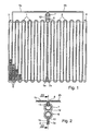
- Fig. 1
- eine Draufsicht auf einen Verdampfer-Rohrblock in Flachrohr-Serpentinenbauweise mit zwei benachbarten Sammelrohren,
- Fig. 2
- eine Detailschnittansicht eines Ausschnitts von Fig. 1 im Bereich der Sammelrohre,
- Fig. 3
- eine Schnittansicht längs der Linie III-III von Fig. 2,
- Fig. 4
- eine Draufsicht auf ein erstes, im Rohrblock der Fig. 1 bis 3 verwendetes Abschlussplattenelement und
- Fig. 5
- eine Draufsicht auf ein zweites, im Rohrblock der Fig. 1 bis 3 verwendetes Abschlussplattenelement.
- Fig. 1
- a plan view of an evaporator tube block in flat tube serpentine construction with two adjacent manifolds,
- Fig. 2
- 1 in the area of the header pipes,
- Fig. 3
- 3 shows a sectional view along the line III-III of FIG. 2,
- Fig. 4
- a plan view of a first, used in the tube block of FIGS. 1 to 3, and
- Fig. 5
- a plan view of a second end plate element used in the tube block of FIGS. 1 to 3.
Der in Fig. 1 dargestellte Rohr-/Rippenblock ist beispielsweise
für einen Verdampfer einer Kraftfahrzeug-Klimaanlage verwendbar,
wobei er problemlos mit einer Druckfestigkeit ausgelegt
werden kann, die für Anlagen benötigt wird, welche mit
dem Kältemittel CO2 arbeiten. Der Rohr-/Rippenblock ist vom
Flachrohr-Serpentinentyp und beinhaltet zwei serpentinenförmige
Mehrkammer-Flachrohre 1, 2, die nebeneinanderliegend zwischen
zwei seitlichen Abschlussplatten 3, 4 angeordnet sind.
Zwischen die einzelnen Serpentinenwindungen der Flachrohre 1,
2 sind in üblicher Weise wärmeleitende Wellrippen 5 eingebracht.The tube / fin block shown in FIG. 1 can be used, for example, for an evaporator of a motor vehicle air conditioning system, and it can be designed without any problems with a pressure resistance which is required for systems which work with the refrigerant CO 2 . The tube / fin block is of the flat tube serpentine type and contains two serpentine multi-chamber
Im Blocklängsmittenbereich grenzen die beiden Serpentinenflachrohre
1, 2 mit ihren inneren Endabschnitten 1a, 2a mit
Berührkontakt aneinander. Die beiden aneinandergrenzenden
Flachrohrendabschnitte 1a, 2a münden an der in Fig. 1 oberen
Blockseite in ein erstes Sammelrohr 6 mit C-förmigem Querschnitt.
Die anderen, äußeren Endabschnitte 1b, 2b der beiden
Serpentinenflachrohre 1, 2 sind an der oberen Blockseite herausgeführt,
durch eine erste rechtwinklige Abwinklung aufeinander
zu nach innen und im Blocklängsmittenbereich durch eine
zweite Abwinklung nach unten geführt und in ein zweites Sammelrohr
7 mit C-förmigem Querschnitt eingefügt, das mit geringem
Abstand über dem ersten Sammelrohr 6 parallel zu diesem
angeordnet ist.The two serpentine flat tubes border in the center of the
Wie insbesondere aus Fig. 2 ersichtlich, sind die beiden äußeren
Endabschnitte 1b, 2b der Serpentinenflachrohre 1, 2 in der
gleichen Weise, wie die beiden inneren Endabschnitte 1a, 2a
mit Berührkontakt aneinanderliegend von unten in das untere
Sammelrohr 6 eingefügt sind, mit ihren abgewinkelten Enden mit
Berührkontakt von oben in das obere Sammelrohr 7 eingefügt.
Zwecks Dichtlötung ist zwischen die in die Sammelrohre 6, 7
eingesteckten, aneinandergrenzenden Flachrohrenden jeweils
Lotfolie 8, 9 eingelegt.As can be seen in particular from FIG. 2, the two outer
Zur Aufnahme der Flachrohrenden weisen die Sammelrohre 6, 7
jeweils einen durchgehenden Längsschlitz 10, 11 auf. Letztere
können fertigungstechnisch sehr einfach ohne spanende Bearbeitung
dadurch realisiert werden, dass die beiden Sammelrohre 6,
7 durch einen umformenden Rundwalzprozess aus jeweils einem
planen Blechstreifen gefertigt werden, der zu der gewünschten
C-Querschnittsform unter Belassung des jeweiligen durchgehenden
Längsschlitzes 10, 11 gebogen wird. Dies bringt eine Ersparnis
an Arbeitsabläufen und vermeidet zudem die Gefahr,
dass Späne in das Sammelrohrinnere gelangen und im späteren
Betrieb zu Verstopfungen des Kältemittelkreislaufs führen können.
Bevorzugt wird lotplattiertes Material für die Sammelrohre
6, 7 verwendet.The
Wie insbesondere aus der Schnittdarstellung von Fig. 3 erkennbar,
ist an jeder der beiden Sammelrohrstirnseiten je ein Abschlussplattenelement
12, 13 vorgesehen, die im gezeigten Beispiel
als 8-förmige, gelochte Plättchen realisiert sind. Die
Fig. 4 und 5 zeigen die beiden Abschlussplättchen 12, 13 in
Einzeldarstellung. Daraus ist erkennbar, dass sie zur Erfüllung
unterschiedlicher Zwecke verschieden gelocht sind.As can be seen in particular from the sectional illustration in FIG. 3,
is an end plate element on each of the two
Das eine, in Fig. 4 gezeigte Abschlussplättchen 12 ist mit
zwei C-förmigen Durchstecköffnungen 14, 15 versehen, die der
C-förmigen Querschnittskontur der Sammelrohre 6, 7 und in ihrer
gegenseitigen Lage der relativen Lage der beiden Sammelrohre
6, 7 zueinander entsprechen. Dieses erste Abschlussplättchen
12 dient auf diese Weise als axial fluiddicht abschließendes
Element. Dazu wird es auf die in Fig. 3 rechte
Stirnseite der beiden parallel untereinanderliegenden Sammelrohre
6, 7 aufgeschoben, bis es seitlich gegen die in die Sammelrohre
6, 7 eingesteckten Flachrohrenden anliegt, wobei die
Sammelrohre 6, 7 durch die querschnittskonturgleichen Durchstecköffnungen
14, 15 hindurchtreten.The one
Auf der gegenüberliegenden Seite wird in analoger Weise das
andere Abschlussplättchen 13 auf die beiden Sammelrohre 6, 7
aufgesteckt, bis es seitlich gegen die in die Sammelrohre 6, 7
eingefügten Flachrohrenden anliegt, wie wiederum in Fig. 3 zu
erkennen. Dieses zweite Abschlussplättchen 13 weist, wie aus
Fig. 5 zu erkennen, im Unterschied zu den C-förmigen Durchstecköffnungen
14, 15 des ersten Abschlussplättchens 12 für
jedes der beiden benachbarten Sammelrohre 6, 7 je eine kreisrunde
Durchstecköffnung 16, 17 auf, deren Durchmesser in etwa
dem Außendurchmesser der Sammelrohre 6, 7 entspricht. Dadurch
treten die Sammelrohre 6, 7 beim Aufschieben des Abschlussplättchens
13 durch die jeweils zugehörige kreisrunde Durchstecköffnung
16, 17 hindurch.On the opposite side, this is done in an analogous manner
Auf die durch diese Durchstecköffnungen 16, 17 durchgeschobenen
Stirnenden der beiden Sammelrohre 6, 7 ist, wie in Fig. 3
dargestellt, je ein endseitig aufgeweitetes Anschlussrohr 18,
19 axial aufgeschoben. Dabei stoßen die Anschlussrohre 18, 19
mit ihrem Stirnende stumpf gegen das Abschlussplättchen 13 an,
das seinerseits mit Stumpfstoß gegen die in die Sammelrohre 6,
7 eingefügten Flachrohrenden anliegt. Diese Stumpfstoßverbindungen
füllen sich beim Lötprozess, in welchem der gesamte
Rohrblockkomplex dichtgelötet wird, fluiddicht mit Lot. Dasselbe
gilt für die fluiddichte Verbindung des anderen Abschlussplättchens
12 einerseits mit den Sammelrohren 6, 7 und
andererseits mit den in diese eingesteckten Flachrohrenden.
Dazu bestehen auch die Abschlussplättchen 12, 13 vorzugsweise
aus lotplattiertem Material.On the pushed through these through
Die der C-Querschnittskontur der Sammelrohre 6, 7 entsprechende
Lochung des in Fig. 4 gezeigten Abschlussplättchens 12 hat
zur Folge, dass dieses mit seinen beiden, von den C-förmigen
Durchstecköffnungen 14, 15 umgebenen Innenbereichen 12a, 12b
den inneren Strömungsquerschnitt der Sammelrohre 6, 7 vollständig
verschließt, d.h. dieses Abschlussplättchen dient als
axiales Verschlusselement, welches die beiden Sammelrohre 6, 7
auf der in Fig. 3 rechten Stirnseite fluiddicht abschließt.That corresponding to the C cross-sectional contour of the
Im Gegensatz dazu lässt das andere Abschlussplättchen 13 mit
seinen kreisrunden Durchstecköffnungen 16, 17 den inneren
Strömungsquerschnitt der beiden Sammelrohre 6, 7 frei, so dass
auf der entsprechenden, in Fig. 3 linken Anschlussseite eine
ungestörte Fluidverbindung jedes der beiden Anschlussrohre 18,
19 mit dem zugehörigen Sammelrohr 6, 7 gegeben ist. Mit dem
jeweiligen Sammelrohr 6,7 stehen andererseits die parallelen
Kammern der beiden Serpentinenflachrohre 1, 2 in Fluidverbindung.
Auf diese Weise kann das verwendete Kältemittel über das
eine Anschlussrohr und das zugehörige Sammelrohr parallel in
die beiden Serpentinenflachrohre 1, 2 verteilt werden, wo es
im Rohrblock je nach gewählter Anschlussrichtung von innen
nach außen oder von außen nach innen strömt, um anschließend
im anderen Sammelrohr wieder gesammelt und über das andere Anschlussrohr
abgeführt zu werden.In contrast, the
Die obige Erläuterung eines bevorzugten Ausführungsbeispiels macht deutlich, dass sich der erfindungsgemäße Wärmeübertrager-Rohrblock mit relativ geringem Aufwand fertigen lässt. Dazu trägt insbesondere bei, dass die Sammelrohre einen durchgehenden Längsschlitz aufweisen, was fertigungstechnisch einfach realisierbar ist und das Einfügen der Flachrohrenden sehr einfach macht, da keine Toleranzen in Axialrichtung beachtet werden müssen. Der axiale Abschluss wird vorteilhafterweise durch die beiden Abschlussplattenelemente bewirkt, die nach dem Einsetzen der Flachrohrenden in die Sammelrohrlängsschlitze auf die Sammelrohre aufgeschoben werden können.The above explanation of a preferred embodiment makes it clear that the heat exchanger tube block according to the invention can be manufactured with relatively little effort. To contributes in particular that the collecting pipes have a continuous Have longitudinal slots, which is technically simple is feasible and the insertion of the flat tube ends is very simple makes, since no tolerances in the axial direction are observed have to. The axial termination is advantageously by causes the two end plate elements after insertion of the flat tube ends in the longitudinal tube slots the manifolds can be pushed on.
Es versteht sich, dass sich der erfindungsgemäße Wärmeübertrager-Rohrblock
nicht nur für Verdampfer von Kraftfahrzeug-Klimaanlagen
eignet, sondern für beliebige andere Wärmeübertrager
mit einem Rohrblockaufbau mit mehreren Sammelrohren
und darin eingesteckten Flachrohren. In weiteren, nicht gezeigten
Realisierungen der Erfindung kann ein Rohrblock mit
geradlinigen Flachrohren vorgesehen sein, und/oder es können
mehr als zwei parallele Sammelrohre vorgesehen sein, wobei wenigstens
ein axial abdichtendes Abschlussplattenelement, das
funktionell dem Abschlussplättchen 12 von Fig. 4 entspricht,
auf zwei oder gegebenenfalls auch mehr dieser Sammelrohre
zwecks axialer Abdichtung aufgesteckt ist. In einer weiteren
alternativen Ausführungsform kann das Abschlussplattenelement
des Typs, bei dem der innere Strömungsquerschnitt der Sammelrohre
wenigstens teilweise frei gelassen wird, wie dies beim
Abschlussplättchen 13 von Fig. 5 der Fall ist, entfallen, wenn
auf der Sammelrohranschlussseite eine entsprechend andere,
herkömmliche Anschlussstruktur gewählt wird. Weiter versteht
sich, dass die Abschlussplattenelemente je nach Anzahl aufzunehmender
Sammelrohre mit einer entsprechenden Anzahl von
Durchstecköffnungen des den Sammelrohr-Strömungsquerschnitt
verschließenden oder frei lassenden Typs versehen sind. Eine
weitere erfindungsgemäße Ausführungsform beinhaltet mehrere in
einer Blocktiefenrichtung senkrecht zur Zeichenebene von Fig.
1 hintereinander angeordnete Rohrblockeinheiten der in Fig. 1
gezeigten Art, wobei sich die beiden Sammelrohre über die gesamte
Blocktiefe erstrecken und gemeinsam von den hintereinanderliegenden
Rohrblockeinheiten genutzt werden können.It is understood that the heat exchanger tube block according to the invention
not only for evaporators of automotive air conditioning systems
suitable, but for any other heat exchanger
with a tube block structure with several manifolds
and flat tubes inserted into it. In other, not shown
A pipe block can be used to implement the invention
rectilinear flat tubes can be provided, and / or it can
more than two parallel manifolds may be provided, at least
an axially sealing end plate element, the
corresponds functionally to the
Claims (2)
Applications Claiming Priority (2)
| Application Number | Priority Date | Filing Date | Title |
|---|---|---|---|
| DE10105202 | 2001-01-31 | ||
| DE10105202A DE10105202A1 (en) | 2001-01-31 | 2001-01-31 | Heat exchanger tube block with several slotted header tubes |
Publications (3)
| Publication Number | Publication Date |
|---|---|
| EP1229295A2 true EP1229295A2 (en) | 2002-08-07 |
| EP1229295A3 EP1229295A3 (en) | 2003-06-04 |
| EP1229295B1 EP1229295B1 (en) | 2006-10-04 |
Family
ID=7672945
Family Applications (1)
| Application Number | Title | Priority Date | Filing Date |
|---|---|---|---|
| EP01130534A Expired - Lifetime EP1229295B1 (en) | 2001-01-31 | 2001-12-21 | Heat exchanger core with several slotted headers |
Country Status (5)
| Country | Link |
|---|---|
| US (1) | US6484796B2 (en) |
| EP (1) | EP1229295B1 (en) |
| JP (1) | JP3974406B2 (en) |
| AT (1) | ATE341744T1 (en) |
| DE (2) | DE10105202A1 (en) |
Families Citing this family (5)
| Publication number | Priority date | Publication date | Assignee | Title |
|---|---|---|---|---|
| US7121364B2 (en) | 2003-02-10 | 2006-10-17 | Western Well Tool, Inc. | Tractor with improved valve system |
| JP4121085B2 (en) * | 2001-12-21 | 2008-07-16 | ベール ゲーエムベーハー ウント コー カーゲー | Especially heat exchanger for automobile |
| US20070039723A1 (en) * | 2005-08-18 | 2007-02-22 | Alex Latcau | Header extension to retain core cover and maintain constant compression on outer fins |
| US11569001B2 (en) | 2008-04-29 | 2023-01-31 | Holtec International | Autonomous self-powered system for removing thermal energy from pools of liquid heated by radioactive materials |
| US10190828B2 (en) * | 2015-10-22 | 2019-01-29 | Hamilton Sundstrand Corporation | Heat exchangers |
Citations (1)
| Publication number | Priority date | Publication date | Assignee | Title |
|---|---|---|---|---|
| DE19846267A1 (en) | 1998-10-08 | 2000-04-13 | Behr Gmbh & Co | Collector tube unit for a heat exchanger |
Family Cites Families (23)
| Publication number | Priority date | Publication date | Assignee | Title |
|---|---|---|---|---|
| CA1117520A (en) * | 1980-06-27 | 1982-02-02 | Bozo Dragojevic | Heat exchange assembly |
| JPS6082790A (en) * | 1983-10-13 | 1985-05-10 | Nippon Denso Co Ltd | Heat exchanger |
| DE3443305A1 (en) | 1984-11-28 | 1986-05-28 | Hoechst Ag, 6230 Frankfurt | METHOD FOR PRODUCING LITHIUM SALTS FROM ANIONIC DYES WITH PREFERRED FIBER REACTIVE GROUPS |
| GB2167699B (en) * | 1984-12-04 | 1988-04-27 | Sanden Corp | A method for producing a heat exchanger |
| SE455727B (en) * | 1984-12-04 | 1988-08-01 | Sanden Corp | HEAT EXCHANGER WITH INLET PIPE AND OUTPUT TUBE, WHICH ONE OF THESE PIPES IS SOME AXIAL CUT FOR CUT TO THE HEAT EXCHANGER |
| USD304855S (en) * | 1985-08-19 | 1989-11-28 | Sanden Corporation | Heat exchanger |
| JPH01144659U (en) * | 1988-03-25 | 1989-10-04 | ||
| DE3843305A1 (en) * | 1988-12-22 | 1990-06-28 | Thermal Waerme Kaelte Klima | CONDENSER FOR A VEHICLE AIR CONDITIONING REFRIGERANT |
| US5036909A (en) * | 1989-06-22 | 1991-08-06 | General Motors Corporation | Multiple serpentine tube heat exchanger |
| JP3043050B2 (en) * | 1990-11-22 | 2000-05-22 | 昭和アルミニウム株式会社 | Heat exchanger |
| US5314013A (en) * | 1991-03-15 | 1994-05-24 | Sanden Corporation | Heat exchanger |
| JPH0754237B2 (en) * | 1992-02-20 | 1995-06-07 | 日本電装株式会社 | Air conditioner condenser |
| US5682944A (en) * | 1992-11-25 | 1997-11-04 | Nippondenso Co., Ltd. | Refrigerant condenser |
| GB2291178A (en) * | 1994-07-09 | 1996-01-17 | Ford Motor Co | Securing cooling tubes to headers |
| FR2748316B1 (en) | 1996-05-03 | 1998-06-26 | Valeo Thermique Moteur Sa | HEAT EXCHANGER WITH TUBULAR COLLECTOR BOX AND FIXING LEG |
| JPH10197190A (en) * | 1997-01-14 | 1998-07-31 | Zexel Corp | Header pipe for heat exchanger |
| DE19729497A1 (en) * | 1997-07-10 | 1999-01-14 | Behr Gmbh & Co | Flat tube heat exchanger for car air-conditioning plant |
| JPH11226685A (en) | 1998-02-16 | 1999-08-24 | Denso Corp | Manufacture of heat exchanger and header tank |
| JP4109746B2 (en) * | 1998-05-20 | 2008-07-02 | 昭和電工株式会社 | Integrated heat exchanger |
| DE19826881B4 (en) * | 1998-06-17 | 2008-01-03 | Behr Gmbh & Co. Kg | Heat exchanger, in particular evaporator |
| DE19911334A1 (en) * | 1999-03-15 | 2000-09-21 | Behr Gmbh & Co | Collecting tube for a heat exchanger and manufacturing process therefor |
| FR2793013B1 (en) * | 1999-04-28 | 2001-07-27 | Valeo Thermique Moteur Sa | BRAZED HEAT EXCHANGER, PARTICULARLY FOR A MOTOR VEHICLE |
| US6185957B1 (en) * | 1999-09-07 | 2001-02-13 | Modine Manufacturing Company | Combined evaporator/accumulator/suctionline heat exchanger |
-
2001
- 2001-01-31 DE DE10105202A patent/DE10105202A1/en not_active Withdrawn
- 2001-12-21 AT AT01130534T patent/ATE341744T1/en not_active IP Right Cessation
- 2001-12-21 EP EP01130534A patent/EP1229295B1/en not_active Expired - Lifetime
- 2001-12-21 DE DE50111146T patent/DE50111146D1/en not_active Expired - Lifetime
-
2002
- 2002-01-18 JP JP2002009661A patent/JP3974406B2/en not_active Expired - Fee Related
- 2002-01-31 US US10/060,085 patent/US6484796B2/en not_active Expired - Fee Related
Patent Citations (1)
| Publication number | Priority date | Publication date | Assignee | Title |
|---|---|---|---|---|
| DE19846267A1 (en) | 1998-10-08 | 2000-04-13 | Behr Gmbh & Co | Collector tube unit for a heat exchanger |
Also Published As
| Publication number | Publication date |
|---|---|
| DE50111146D1 (en) | 2006-11-16 |
| US20020112849A1 (en) | 2002-08-22 |
| JP2002228388A (en) | 2002-08-14 |
| ATE341744T1 (en) | 2006-10-15 |
| JP3974406B2 (en) | 2007-09-12 |
| US6484796B2 (en) | 2002-11-26 |
| DE10105202A1 (en) | 2002-08-01 |
| EP1229295A3 (en) | 2003-06-04 |
| EP1229295B1 (en) | 2006-10-04 |
Similar Documents
| Publication | Publication Date | Title |
|---|---|---|
| DE102005015799B4 (en) | Refrigerant evaporator | |
| EP0632245B1 (en) | Water-air heat exchanger of aluminium for motor vehicles | |
| DE19883002B4 (en) | Heat exchanger line and heat exchanger with such a heat exchanger line | |
| EP0964218B1 (en) | Heat exchanger with flat finned tubes, more particularly radiator,cooler,condenser or evaporator for automotive vehicle | |
| EP1613916B1 (en) | Heat exchanger | |
| EP0374896A2 (en) | Flat tube condenser, manufacturing method and uses | |
| DE102007051194A1 (en) | Cooling heat exchanger | |
| EP1840494A2 (en) | Heat exchanger profile | |
| EP0566899B1 (en) | Heat exchanger, particularly evaporator | |
| DE4305060C2 (en) | Soldered heat exchanger, especially evaporator | |
| EP0912869B1 (en) | Flat tube heat exchanger with more than two flows and a deflecting bottom for motor vehicles, and process for manufacturing the same | |
| EP0929784B1 (en) | Motor vehicle flat tube heat exchanger with flat tubes retained on collars of a tube bottom | |
| DE19933913C2 (en) | Evaporator of an automotive air conditioning system | |
| DE102006002932B4 (en) | Heat exchangers and manufacturing processes for heat exchangers | |
| DE102004002252B4 (en) | Heat exchanger for vehicles | |
| EP1411310B1 (en) | Heat exhanger with serpentine structure | |
| EP2798299B1 (en) | Heat exchanger | |
| EP2710318A1 (en) | Multiplate heat exchanger | |
| DE4330214B4 (en) | heat exchangers | |
| EP1229295B1 (en) | Heat exchanger core with several slotted headers | |
| EP1926961B1 (en) | Heat exchanger, in particular gas cooler | |
| EP3491323B1 (en) | Heat exchanger having a micro-channel structure or wing tube structure | |
| EP0268831B1 (en) | Plate fin | |
| DE10241635A1 (en) | Flat pipe heat exchanger for a heating or air-conditioning system of a motor vehicle comprises a collecting tube, and flat pipe elements connected to the collecting tube and having a torsion region | |
| EP2994712B1 (en) | Heat exchanger |
Legal Events
| Date | Code | Title | Description |
|---|---|---|---|
| PUAI | Public reference made under article 153(3) epc to a published international application that has entered the european phase |
Free format text: ORIGINAL CODE: 0009012 |
|
| AK | Designated contracting states |
Kind code of ref document: A2 Designated state(s): AT BE CH CY DE DK ES FI FR GB GR IE IT LI LU MC NL PT SE TR |
|
| AX | Request for extension of the european patent |
Free format text: AL;LT;LV;MK;RO;SI |
|
| PUAL | Search report despatched |
Free format text: ORIGINAL CODE: 0009013 |
|
| AK | Designated contracting states |
Designated state(s): AT BE CH CY DE DK ES FI FR GB GR IE IT LI LU MC NL PT SE TR |
|
| AX | Request for extension of the european patent |
Extension state: AL LT LV MK RO SI |
|
| 17P | Request for examination filed |
Effective date: 20031118 |
|
| AKX | Designation fees paid |
Designated state(s): AT BE CH CY DE DK ES FI FR GB GR IE IT LI LU MC NL PT SE TR |
|
| RAP1 | Party data changed (applicant data changed or rights of an application transferred) |
Owner name: BEHR GMBH & CO. KG |
|
| GRAP | Despatch of communication of intention to grant a patent |
Free format text: ORIGINAL CODE: EPIDOSNIGR1 |
|
| GRAS | Grant fee paid |
Free format text: ORIGINAL CODE: EPIDOSNIGR3 |
|
| GRAA | (expected) grant |
Free format text: ORIGINAL CODE: 0009210 |
|
| AK | Designated contracting states |
Kind code of ref document: B1 Designated state(s): AT BE CH CY DE DK ES FI FR GB GR IE IT LI LU MC NL PT SE TR |
|
| PG25 | Lapsed in a contracting state [announced via postgrant information from national office to epo] |
Ref country code: IT Free format text: LAPSE BECAUSE OF FAILURE TO SUBMIT A TRANSLATION OF THE DESCRIPTION OR TO PAY THE FEE WITHIN THE PRESCRIBED TIME-LIMIT;WARNING: LAPSES OF ITALIAN PATENTS WITH EFFECTIVE DATE BEFORE 2007 MAY HAVE OCCURRED AT ANY TIME BEFORE 2007. THE CORRECT EFFECTIVE DATE MAY BE DIFFERENT FROM THE ONE RECORDED. Effective date: 20061004 Ref country code: NL Free format text: LAPSE BECAUSE OF FAILURE TO SUBMIT A TRANSLATION OF THE DESCRIPTION OR TO PAY THE FEE WITHIN THE PRESCRIBED TIME-LIMIT Effective date: 20061004 Ref country code: IE Free format text: LAPSE BECAUSE OF FAILURE TO SUBMIT A TRANSLATION OF THE DESCRIPTION OR TO PAY THE FEE WITHIN THE PRESCRIBED TIME-LIMIT Effective date: 20061004 Ref country code: FI Free format text: LAPSE BECAUSE OF FAILURE TO SUBMIT A TRANSLATION OF THE DESCRIPTION OR TO PAY THE FEE WITHIN THE PRESCRIBED TIME-LIMIT Effective date: 20061004 |
|
| REG | Reference to a national code |
Ref country code: GB Ref legal event code: FG4D Free format text: NOT ENGLISH |
|
| REG | Reference to a national code |
Ref country code: CH Ref legal event code: EP |
|
| REG | Reference to a national code |
Ref country code: IE Ref legal event code: FG4D Free format text: LANGUAGE OF EP DOCUMENT: GERMAN |
|
| REF | Corresponds to: |
Ref document number: 50111146 Country of ref document: DE Date of ref document: 20061116 Kind code of ref document: P |
|
| PG25 | Lapsed in a contracting state [announced via postgrant information from national office to epo] |
Ref country code: LI Free format text: LAPSE BECAUSE OF NON-PAYMENT OF DUE FEES Effective date: 20061231 Ref country code: CH Free format text: LAPSE BECAUSE OF NON-PAYMENT OF DUE FEES Effective date: 20061231 Ref country code: MC Free format text: LAPSE BECAUSE OF NON-PAYMENT OF DUE FEES Effective date: 20061231 Ref country code: BE Free format text: LAPSE BECAUSE OF NON-PAYMENT OF DUE FEES Effective date: 20061231 |
|
| PG25 | Lapsed in a contracting state [announced via postgrant information from national office to epo] |
Ref country code: DK Free format text: LAPSE BECAUSE OF FAILURE TO SUBMIT A TRANSLATION OF THE DESCRIPTION OR TO PAY THE FEE WITHIN THE PRESCRIBED TIME-LIMIT Effective date: 20070104 Ref country code: SE Free format text: LAPSE BECAUSE OF FAILURE TO SUBMIT A TRANSLATION OF THE DESCRIPTION OR TO PAY THE FEE WITHIN THE PRESCRIBED TIME-LIMIT Effective date: 20070104 |
|
| PG25 | Lapsed in a contracting state [announced via postgrant information from national office to epo] |
Ref country code: ES Free format text: LAPSE BECAUSE OF FAILURE TO SUBMIT A TRANSLATION OF THE DESCRIPTION OR TO PAY THE FEE WITHIN THE PRESCRIBED TIME-LIMIT Effective date: 20070115 |
|
| PG25 | Lapsed in a contracting state [announced via postgrant information from national office to epo] |
Ref country code: PT Free format text: LAPSE BECAUSE OF FAILURE TO SUBMIT A TRANSLATION OF THE DESCRIPTION OR TO PAY THE FEE WITHIN THE PRESCRIBED TIME-LIMIT Effective date: 20070316 |
|
| NLV1 | Nl: lapsed or annulled due to failure to fulfill the requirements of art. 29p and 29m of the patents act | ||
| ET | Fr: translation filed | ||
| GBV | Gb: ep patent (uk) treated as always having been void in accordance with gb section 77(7)/1977 [no translation filed] |
Effective date: 20061004 |
|
| REG | Reference to a national code |
Ref country code: IE Ref legal event code: FD4D |
|
| PLBE | No opposition filed within time limit |
Free format text: ORIGINAL CODE: 0009261 |
|
| STAA | Information on the status of an ep patent application or granted ep patent |
Free format text: STATUS: NO OPPOSITION FILED WITHIN TIME LIMIT |
|
| REG | Reference to a national code |
Ref country code: CH Ref legal event code: PL |
|
| 26N | No opposition filed |
Effective date: 20070705 |
|
| PG25 | Lapsed in a contracting state [announced via postgrant information from national office to epo] |
Ref country code: GB Free format text: LAPSE BECAUSE OF FAILURE TO SUBMIT A TRANSLATION OF THE DESCRIPTION OR TO PAY THE FEE WITHIN THE PRESCRIBED TIME-LIMIT Effective date: 20061004 |
|
| BERE | Be: lapsed |
Owner name: BEHR G.M.B.H. & CO. KG Effective date: 20061231 |
|
| PG25 | Lapsed in a contracting state [announced via postgrant information from national office to epo] |
Ref country code: AT Free format text: LAPSE BECAUSE OF NON-PAYMENT OF DUE FEES Effective date: 20061221 |
|
| PG25 | Lapsed in a contracting state [announced via postgrant information from national office to epo] |
Ref country code: GR Free format text: LAPSE BECAUSE OF FAILURE TO SUBMIT A TRANSLATION OF THE DESCRIPTION OR TO PAY THE FEE WITHIN THE PRESCRIBED TIME-LIMIT Effective date: 20070105 |
|
| PG25 | Lapsed in a contracting state [announced via postgrant information from national office to epo] |
Ref country code: TR Free format text: LAPSE BECAUSE OF FAILURE TO SUBMIT A TRANSLATION OF THE DESCRIPTION OR TO PAY THE FEE WITHIN THE PRESCRIBED TIME-LIMIT Effective date: 20061004 Ref country code: LU Free format text: LAPSE BECAUSE OF NON-PAYMENT OF DUE FEES Effective date: 20061221 |
|
| PG25 | Lapsed in a contracting state [announced via postgrant information from national office to epo] |
Ref country code: CY Free format text: LAPSE BECAUSE OF FAILURE TO SUBMIT A TRANSLATION OF THE DESCRIPTION OR TO PAY THE FEE WITHIN THE PRESCRIBED TIME-LIMIT Effective date: 20061004 |
|
| PGFP | Annual fee paid to national office [announced via postgrant information from national office to epo] |
Ref country code: FR Payment date: 20100106 Year of fee payment: 9 |
|
| PGFP | Annual fee paid to national office [announced via postgrant information from national office to epo] |
Ref country code: DE Payment date: 20091229 Year of fee payment: 9 |
|
| REG | Reference to a national code |
Ref country code: FR Ref legal event code: ST Effective date: 20110831 |
|
| PG25 | Lapsed in a contracting state [announced via postgrant information from national office to epo] |
Ref country code: FR Free format text: LAPSE BECAUSE OF NON-PAYMENT OF DUE FEES Effective date: 20110103 |
|
| REG | Reference to a national code |
Ref country code: DE Ref legal event code: R119 Ref document number: 50111146 Country of ref document: DE Effective date: 20110701 |
|
| PG25 | Lapsed in a contracting state [announced via postgrant information from national office to epo] |
Ref country code: DE Free format text: LAPSE BECAUSE OF NON-PAYMENT OF DUE FEES Effective date: 20110701 |