EP0632245B1 - Water-air heat exchanger of aluminium for motor vehicles - Google Patents
Water-air heat exchanger of aluminium for motor vehicles Download PDFInfo
- Publication number
- EP0632245B1 EP0632245B1 EP94110227A EP94110227A EP0632245B1 EP 0632245 B1 EP0632245 B1 EP 0632245B1 EP 94110227 A EP94110227 A EP 94110227A EP 94110227 A EP94110227 A EP 94110227A EP 0632245 B1 EP0632245 B1 EP 0632245B1
- Authority
- EP
- European Patent Office
- Prior art keywords
- flat
- heat exchanger
- partition
- tube
- exchanger according
- Prior art date
- Legal status (The legal status is an assumption and is not a legal conclusion. Google has not performed a legal analysis and makes no representation as to the accuracy of the status listed.)
- Expired - Lifetime
Links
Images

Classifications
-
- F—MECHANICAL ENGINEERING; LIGHTING; HEATING; WEAPONS; BLASTING
- F28—HEAT EXCHANGE IN GENERAL
- F28F—DETAILS OF HEAT-EXCHANGE AND HEAT-TRANSFER APPARATUS, OF GENERAL APPLICATION
- F28F3/00—Plate-like or laminated elements; Assemblies of plate-like or laminated elements
- F28F3/02—Elements or assemblies thereof with means for increasing heat-transfer area, e.g. with fins, with recesses, with corrugations
- F28F3/04—Elements or assemblies thereof with means for increasing heat-transfer area, e.g. with fins, with recesses, with corrugations the means being integral with the element
- F28F3/042—Elements or assemblies thereof with means for increasing heat-transfer area, e.g. with fins, with recesses, with corrugations the means being integral with the element in the form of local deformations of the element
- F28F3/044—Elements or assemblies thereof with means for increasing heat-transfer area, e.g. with fins, with recesses, with corrugations the means being integral with the element in the form of local deformations of the element the deformations being pontual, e.g. dimples
-
- B—PERFORMING OPERATIONS; TRANSPORTING
- B60—VEHICLES IN GENERAL
- B60H—ARRANGEMENTS OF HEATING, COOLING, VENTILATING OR OTHER AIR-TREATING DEVICES SPECIALLY ADAPTED FOR PASSENGER OR GOODS SPACES OF VEHICLES
- B60H1/00—Heating, cooling or ventilating [HVAC] devices
- B60H1/00321—Heat exchangers for air-conditioning devices
- B60H1/00328—Heat exchangers for air-conditioning devices of the liquid-air type
-
- F—MECHANICAL ENGINEERING; LIGHTING; HEATING; WEAPONS; BLASTING
- F28—HEAT EXCHANGE IN GENERAL
- F28D—HEAT-EXCHANGE APPARATUS, NOT PROVIDED FOR IN ANOTHER SUBCLASS, IN WHICH THE HEAT-EXCHANGE MEDIA DO NOT COME INTO DIRECT CONTACT
- F28D1/00—Heat-exchange apparatus having stationary conduit assemblies for one heat-exchange medium only, the media being in contact with different sides of the conduit wall, in which the other heat-exchange medium is a large body of fluid, e.g. domestic or motor car radiators
- F28D1/02—Heat-exchange apparatus having stationary conduit assemblies for one heat-exchange medium only, the media being in contact with different sides of the conduit wall, in which the other heat-exchange medium is a large body of fluid, e.g. domestic or motor car radiators with heat-exchange conduits immersed in the body of fluid
- F28D1/03—Heat-exchange apparatus having stationary conduit assemblies for one heat-exchange medium only, the media being in contact with different sides of the conduit wall, in which the other heat-exchange medium is a large body of fluid, e.g. domestic or motor car radiators with heat-exchange conduits immersed in the body of fluid with plate-like or laminated conduits
- F28D1/0308—Heat-exchange apparatus having stationary conduit assemblies for one heat-exchange medium only, the media being in contact with different sides of the conduit wall, in which the other heat-exchange medium is a large body of fluid, e.g. domestic or motor car radiators with heat-exchange conduits immersed in the body of fluid with plate-like or laminated conduits the conduits being formed by paired plates touching each other
- F28D1/035—Heat-exchange apparatus having stationary conduit assemblies for one heat-exchange medium only, the media being in contact with different sides of the conduit wall, in which the other heat-exchange medium is a large body of fluid, e.g. domestic or motor car radiators with heat-exchange conduits immersed in the body of fluid with plate-like or laminated conduits the conduits being formed by paired plates touching each other with U-flow or serpentine-flow inside the conduits
-
- F—MECHANICAL ENGINEERING; LIGHTING; HEATING; WEAPONS; BLASTING
- F28—HEAT EXCHANGE IN GENERAL
- F28D—HEAT-EXCHANGE APPARATUS, NOT PROVIDED FOR IN ANOTHER SUBCLASS, IN WHICH THE HEAT-EXCHANGE MEDIA DO NOT COME INTO DIRECT CONTACT
- F28D1/00—Heat-exchange apparatus having stationary conduit assemblies for one heat-exchange medium only, the media being in contact with different sides of the conduit wall, in which the other heat-exchange medium is a large body of fluid, e.g. domestic or motor car radiators
- F28D1/02—Heat-exchange apparatus having stationary conduit assemblies for one heat-exchange medium only, the media being in contact with different sides of the conduit wall, in which the other heat-exchange medium is a large body of fluid, e.g. domestic or motor car radiators with heat-exchange conduits immersed in the body of fluid
- F28D1/03—Heat-exchange apparatus having stationary conduit assemblies for one heat-exchange medium only, the media being in contact with different sides of the conduit wall, in which the other heat-exchange medium is a large body of fluid, e.g. domestic or motor car radiators with heat-exchange conduits immersed in the body of fluid with plate-like or laminated conduits
- F28D1/0391—Heat-exchange apparatus having stationary conduit assemblies for one heat-exchange medium only, the media being in contact with different sides of the conduit wall, in which the other heat-exchange medium is a large body of fluid, e.g. domestic or motor car radiators with heat-exchange conduits immersed in the body of fluid with plate-like or laminated conduits a single plate being bent to form one or more conduits
-
- F—MECHANICAL ENGINEERING; LIGHTING; HEATING; WEAPONS; BLASTING
- F28—HEAT EXCHANGE IN GENERAL
- F28F—DETAILS OF HEAT-EXCHANGE AND HEAT-TRANSFER APPARATUS, OF GENERAL APPLICATION
- F28F9/00—Casings; Header boxes; Auxiliary supports for elements; Auxiliary members within casings
- F28F9/02—Header boxes; End plates
- F28F9/04—Arrangements for sealing elements into header boxes or end plates
- F28F9/16—Arrangements for sealing elements into header boxes or end plates by permanent joints, e.g. by rolling
- F28F9/18—Arrangements for sealing elements into header boxes or end plates by permanent joints, e.g. by rolling by welding
- F28F9/182—Arrangements for sealing elements into header boxes or end plates by permanent joints, e.g. by rolling by welding the heat-exchange conduits having ends with a particular shape, e.g. deformed; the heat-exchange conduits or end plates having supplementary joining means, e.g. abutments
-
- F—MECHANICAL ENGINEERING; LIGHTING; HEATING; WEAPONS; BLASTING
- F28—HEAT EXCHANGE IN GENERAL
- F28F—DETAILS OF HEAT-EXCHANGE AND HEAT-TRANSFER APPARATUS, OF GENERAL APPLICATION
- F28F9/00—Casings; Header boxes; Auxiliary supports for elements; Auxiliary members within casings
- F28F9/26—Arrangements for connecting different sections of heat-exchange elements, e.g. of radiators
- F28F9/262—Arrangements for connecting different sections of heat-exchange elements, e.g. of radiators for radiators
-
- F—MECHANICAL ENGINEERING; LIGHTING; HEATING; WEAPONS; BLASTING
- F28—HEAT EXCHANGE IN GENERAL
- F28D—HEAT-EXCHANGE APPARATUS, NOT PROVIDED FOR IN ANOTHER SUBCLASS, IN WHICH THE HEAT-EXCHANGE MEDIA DO NOT COME INTO DIRECT CONTACT
- F28D1/00—Heat-exchange apparatus having stationary conduit assemblies for one heat-exchange medium only, the media being in contact with different sides of the conduit wall, in which the other heat-exchange medium is a large body of fluid, e.g. domestic or motor car radiators
- F28D1/02—Heat-exchange apparatus having stationary conduit assemblies for one heat-exchange medium only, the media being in contact with different sides of the conduit wall, in which the other heat-exchange medium is a large body of fluid, e.g. domestic or motor car radiators with heat-exchange conduits immersed in the body of fluid
- F28D1/04—Heat-exchange apparatus having stationary conduit assemblies for one heat-exchange medium only, the media being in contact with different sides of the conduit wall, in which the other heat-exchange medium is a large body of fluid, e.g. domestic or motor car radiators with heat-exchange conduits immersed in the body of fluid with tubular conduits
- F28D1/053—Heat-exchange apparatus having stationary conduit assemblies for one heat-exchange medium only, the media being in contact with different sides of the conduit wall, in which the other heat-exchange medium is a large body of fluid, e.g. domestic or motor car radiators with heat-exchange conduits immersed in the body of fluid with tubular conduits the conduits being straight
- F28D1/0535—Heat-exchange apparatus having stationary conduit assemblies for one heat-exchange medium only, the media being in contact with different sides of the conduit wall, in which the other heat-exchange medium is a large body of fluid, e.g. domestic or motor car radiators with heat-exchange conduits immersed in the body of fluid with tubular conduits the conduits being straight the conduits having a non-circular cross-section
- F28D1/05366—Assemblies of conduits connected to common headers, e.g. core type radiators
- F28D1/05391—Assemblies of conduits connected to common headers, e.g. core type radiators with multiple rows of conduits or with multi-channel conduits combined with a particular flow pattern, e.g. multi-row multi-stage radiators
-
- F—MECHANICAL ENGINEERING; LIGHTING; HEATING; WEAPONS; BLASTING
- F28—HEAT EXCHANGE IN GENERAL
- F28D—HEAT-EXCHANGE APPARATUS, NOT PROVIDED FOR IN ANOTHER SUBCLASS, IN WHICH THE HEAT-EXCHANGE MEDIA DO NOT COME INTO DIRECT CONTACT
- F28D21/00—Heat-exchange apparatus not covered by any of the groups F28D1/00 - F28D20/00
- F28D2021/0019—Other heat exchangers for particular applications; Heat exchange systems not otherwise provided for
- F28D2021/008—Other heat exchangers for particular applications; Heat exchange systems not otherwise provided for for vehicles
- F28D2021/0091—Radiators
- F28D2021/0094—Radiators for recooling the engine coolant
-
- F—MECHANICAL ENGINEERING; LIGHTING; HEATING; WEAPONS; BLASTING
- F28—HEAT EXCHANGE IN GENERAL
- F28D—HEAT-EXCHANGE APPARATUS, NOT PROVIDED FOR IN ANOTHER SUBCLASS, IN WHICH THE HEAT-EXCHANGE MEDIA DO NOT COME INTO DIRECT CONTACT
- F28D21/00—Heat-exchange apparatus not covered by any of the groups F28D1/00 - F28D20/00
- F28D2021/0019—Other heat exchangers for particular applications; Heat exchange systems not otherwise provided for
- F28D2021/008—Other heat exchangers for particular applications; Heat exchange systems not otherwise provided for for vehicles
- F28D2021/0091—Radiators
- F28D2021/0096—Radiators for space heating
-
- F—MECHANICAL ENGINEERING; LIGHTING; HEATING; WEAPONS; BLASTING
- F28—HEAT EXCHANGE IN GENERAL
- F28F—DETAILS OF HEAT-EXCHANGE AND HEAT-TRANSFER APPARATUS, OF GENERAL APPLICATION
- F28F1/00—Tubular elements; Assemblies of tubular elements
- F28F1/02—Tubular elements of cross-section which is non-circular
- F28F2001/027—Tubular elements of cross-section which is non-circular with dimples
Definitions
- the invention relates to a water / air heat exchanger made of aluminum or an aluminum alloy for motor vehicles, in particular to a heating heat exchanger or engine cooler, according to the preamble of claim 1.
- a heat exchanger is known from JP-A-32 38 165.
- the alloys AlMnl or AlMgSi or A199.5 are particularly suitable as aluminum alloys for such heat exchangers, the former two alloys preferably being used for pipes, water boxes and plates and the latter alloy preferably being used for zigzag fins.
- Pipes and water boxes are appropriately pre-coated on both sides with hard solder AlSi7.
- This solder coating is applied with flux, e.g. sprayed a sodium fluoride and potassium aluminum fluoride.
- the soldering to the end product, which is protected according to the invention, is then carried out in a soldering furnace under protective gas without the addition of further solder to the precoating.
- Water / air heat exchangers such as engine coolers or in particular heating heat exchangers, to which the invention is based in particular, are also heat exchangers which, in contrast to evaporators or condensers in a cooling circuit be arranged within a motor vehicle.
- a cooling circuit uses water or water with an anti-freeze additive such as glycol as the internal heat exchange medium.
- the ambient air serves as the external heat exchange medium.
- Such water / air heat exchangers for motor vehicles are thus operated at a relatively low internal pressure, specifically at an operating pressure of approximately 1.5 to at most 2 bar and an inlet pressure of in particular 4 bar.
- evaporators and condensers of air conditioning systems in motor vehicles have a non-water-based coolant, for example the fluorochlorohydrocarbons now now considered to be environmentally harmful or now fluorocarbons, and must be designed for high internal operating pressures, such as typically operating pressures of about 25 bar and burst pressures of over 100 bar (e.g. 105 bar).
- the design criteria of heat exchangers according to the invention and of evaporators and condensers in motor vehicles are therefore fundamentally different from the outset because of the different strength requirements.
- water / air heat exchangers for motor vehicles are large-scale products, although a large motor vehicle manufacturer can already produce quantities of around half a million to well over one million per year in a single type of car. Large-scale products of this type therefore have the character of mass-produced items, in which small cost savings are of great importance in the context of the cost optimization that is always demanded from the motor vehicle manufacturers, especially since, within the scope of such optimization work, no compromises should be made with regard to the optimal functionality at the same time.
- heat exchangers for motor vehicles put together from aluminum pipes and water boxes made of plastic have been preferred for cost reasons, since the known heat exchangers made of all-aluminum, ie including the aluminum water box, because of the various complex ones Steps in soldering were more expensive to manufacture, although the additional cost was only justifiable due to the recyclability.
- the material of the lid of the water tank should initially remain open in a heat exchanger which is referred to as consisting of aluminum (or an aluminum alloy), so that this lid may continue to be made of plastic and can be dismantled before the recycling process .
- the tube sheet is made of aluminum or an aluminum alloy.
- the possibility known per se in heat exchangers on the market is also included, also to manufacture the water tank completely from aluminum, so that its tube sheet and its Lids are both made of aluminum or an aluminum alloy and are brazed together.
- the water / air heat exchangers to which the invention relates are operated in cross-countercurrent. At least double-flow heat exchangers are required for such operation in cross-counterflow. In this case, however, it is also possible to connect two-row and multi-row or in particular two-port and multiple-flow heat exchangers in parallel with lower flow requirements and then operate them only in a single cross flow. In the context of the invention, such a structure, which would also be included in the borderline case, would then strictly speaking not be multi-flow, but only multi-row. As mentioned, however, reference is made in the context of the invention in particular to real multi-flow.
- the flat tubes themselves with at least one partition wall running in the longitudinal direction, the partition wall in each case between adjacent opposing floods in a connection area at the Water tank distant ends of the flat tubes is recessed over a length, along which the neighboring opposing floods communicate.
- the partition wall which only extends over a limited length of the flat tube, is subsequently inserted into the flat tube body, be it as a simple partition wall fixed by retaining knobs, or as a partition wall in combination with turbulence-generating arms, which at the same time serve for centering in the flat tubes.
- This method of production is also cumbersome and expensive in view of the narrow clear widths of the flat tubes.
- the partition wall is formed by deforming the sheet metal part forming the flat tube, by forming a bead up to the opposite wall.
- the entire flat tube is already formed from a single sheet metal part, the partition wall itself being formed by deforming this sheet metal part .
- both ends of the sheet metal part are bent so that together they produce a double-walled form of the partition.
- the connection area of the opposing floods is created by a cutout in the sheet metal part.
- the solder gap length is practically zero. But if the cut in the connection area is chosen so that there is still some soldering gap, it is inevitably very small in the context of this known construction.
- turbulence can occur in the connection area due to the construction of the double-walled partition and its connection to the inner wall surfaces of the flat sides of the flat tube.
- the invention is therefore based on the object of further optimizing a heat exchanger of the generic type, both in terms of cost and function, with minimal use of material, special emphasis being placed on the lowest possible resistance on the heating medium with the highest possible internal heat transfer coefficient and neither during the soldering process nor during operation by the Construction faults should occur.
- the supporting indentations provided according to the invention according to the second characteristic feature not only have the usual function as turbulators, but also complement the support of the two flat sides against one another in such a way that the single wall of the partition wall no longer plays a role with regard to the dimensional stability, but the support function is even overcompensated .
- the type of formation of the partition wall with a flush overlap with the areas of the flat sides of the flat tubes that continue in the region of the partition wall also offers the advantage that, even in the area of the connection area where the two flows of the flat tube adjoin one another, soldering can take place over a sufficiently long soldering path, which can be freely selected by choosing the length of the overlap area.
- the indentations act as such turbulators, which are specifically designed for the narrow flat tubes that occur in practice, while turbulence inserts, such as those used in DE-C2- 3 440 489, hardly even with narrow flat tubes, even according to their own statements in this prior publication have a turbulent meaning.
- the high pressure stability of the heat exchanger according to the invention is particularly important, particularly in the case of heating heat exchangers for motor vehicles, which are positioned in the vehicle interior and which are supposed to be more stable against internal burst pressure than an engine cooler which is switched on in the same circuit.
- an external flux access for soldering the partition of the respective flat tube is then expediently provided to enable the soldering, which is closed after the soldering by the solder, wherein this external flux access can be provided in the area of an overlap in the area of the flush connections on both sides, without having to form a separate flux window in certain applications.
- such a window is preferably additionally created by forming guide channels for flux in the sheet metal part in the overlap region along the overlap distance.
- a cutout can be formed, for example punched out, in the connection area of the communication between the two floods, which is exact there corresponds to the clear internal cross section of the flat tube. Since the flat tube is flush on the outside in this area, but is double-walled due to the overlap, a throttling restriction of one wall thickness of the flat tube is obtained on each side of the flat tube. Because of the way of production, bent back beads do not have to be reverted to, as was the case in DE-C2-3 440 489. One can also avoid the asymmetry of the known case due to the bending only in one direction.
- a further development according to claim 11 is preferred, in which, in the connection area for communicating the opposing floods, the sheet metal part is cut out not only as a continuation of the partition, but also subsequently, preferably on both sides, along a partial section of its overlap.
- the influence of double wall thickness in the overlap area on the resistance coefficient can be made less effective in the connection area, so that there is practically only a reduction in communication by one wall thickness of the flat tube.
- the upper limit of the narrowing of the communication in the connection area of the opposing floods can preferably also be reduced to approximately a wall thickness of the flat tube.
- the boundary of the cut-out then runs obliquely, preferably at an angle ⁇ of 30 ° to 60 ° with respect to the planes of the flat sides of the flat tube, a further reduction in the drag coefficient is obtained by good flow transitions on the inner wall surface of the flat tube.
- the bundle of flat tubes and zigzag fins is held in the base plate of the water box at one end of the flat tubes.
- the ends of the flat tubes remote from the water box are soldered into grooves in an end plate.
- the end of the flat tubes is brought about at the end of their connection area for the communication of the opposing floods.
- the end plate can also be used as a flange for receiving the heat exchanger in a holding housing in the motor vehicle.
- the package of flat tubes and zigzag fins is expediently held between side plates and soldered to them.
- the side plates then engage in a form-fitting manner in holding recesses in the tube sheet of the water tank and the end plate soldered.
- the package of flat tubes and zigzag fins is edged between the two side plates. Then the side plates are moved towards each other until the arrangement of the flat tubes corresponds to the division in the tube sheet. Then, on one side of the water box and on the other side, the end plate can be pressed on and latched in, the side plates serving as an axial spacer between the water box and the end plate. After such a latching process, the package that has not yet been soldered can be transferred to the soldering furnace in the correct mutual position without the need for other holding aids and soldered there.
- the wall indentations are preferably provided in a grid of points, even in order to dent the solder connection points on the zigzag fins as little as possible on the outside and thus to create the largest possible contact surface of the outside of the flat tube with the zigzag fins.
- This effect can be improved if the grid, be it only a point grid or another, is oriented at an angle deviating from 90 °, preferably from 3 ° to 20 °, with respect to the axis of the respective flat tube. This makes it possible to ensure that the flat individual slats do not match the continuation direction of the grid.
- the flat tube in which the flat tube is formed from a sheet metal part by folding, it makes sense to precoat the sheet metal part on both sides with solder.
- This two-sided pre-coating also serves, for example, to solder the indentations to one another on the inside and to the outside to solder the zigzag lamellae and in the slot in the tube sheet.
- An aluminum hard solder as in general is also possible as a solder.
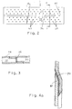
- the double-flow heat exchanger according to FIG. 1 has a series of parallel, in turn double-flow, flat tubes 2, the parallel flat sides of which lie opposite one another and nest zigzag fins 4 between them, which are also arranged on the outer flat sides of the outer flat tubes.
- the zigzag fins 4 and the flat tubes 2 are soldered together to form a block in the finished heat exchanger by means of aluminum brazing solder, not shown.
- the wall thickness of the flat tubes 2 is in particular 0.2 to 0.6 mm, preferably 0.3 to 0.4 mm.
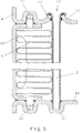
- a water tank 6 is connected in communication with the flat tubes 2.
- the water box 6 consists of a tube sheet 8 and a cover 10, which in turn are soldered together by aluminum brazing.
- the zigzag fins 4 and the other components described below consist of aluminum or an aluminum alloy, so that the entire heat exchanger consists essentially of aluminum.
- only one water tank 6 is provided.
- Its tube sheet 8, as shown in FIG. 1, has parallel slots (12 in FIG. 5) into which one end of the flat tube 2 is inserted.
- the tube sheet consists of an aluminum sheet with a thickness of, for example, 1.2 mm. This sheet is cut at the locations of the slots. The edges of the cuts then become too Collar (14 in Fig. 5) bent.
- the ends of the double-flow flat tubes 2 are inserted into their respective slots 12 to such an extent that free ends 16 of the flat tubes protrude beyond the collars.
- the free ends 16 are sculpted.
- the tulips are placed on the two long sides of the respective slot around the respective collar so far that the respective collar is gripped by more than 90 ° so that an undercut effect is achieved and a defined, extended soldering gap is formed between the bent-back tulip and the collar becomes.
- the tube sheet 8 is box-shaped with a circumferential side wall 24 and has a circumferential outer flange 26 which has a circumferential outer collar 28.
- the flat cover 10 of the water tank 6 is inserted between the outer flange 26 and the outer collar 28 and is soldered to the aluminum braze in a manner not shown.
- the lid 10 carries a partition 30 which divides the water tank 6 into two sections. One communicates with the inlet 32 and the other with the outlet 34 of the water as an internal heat exchange fluid.
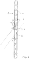
- the flat tubes 2 are in the middle provided with a partition 36, which is arranged in the same plane as the partition 30 in the water tank.
- the partition walls 36 divide the respective flat tube 2 into two parallel channels 38, in which the inner heat exchanger fluid flows in countercurrent in accordance with the direction of flow indicated by arrows at the connections 32 and 34.
- This connection in counterflow is a double-flow flat tube 2.
- the flow is diverted at the ends of the flat tubes 2 facing away from the water tank 6 in that the two channels and thus the adjacent floods communicate as little throttled as possible.
- the partition 36 is omitted in this connection area 40 over such a length that the cross section of one channel 38 is completely or almost unthrottled in that of the other Channel 38 is transferred.
- the length over which the partition 36 is omitted in the connection area 40 of the communication is half to three times the distance between the outer wall and the partition 36 of the respective flat tube 2. In practical embodiments, this distance is in particular 0.5 to 2 mm.
- the other ends of the flat tubes 2 facing away from the water box 6 openly engage in grooves 42 of an end plate 44 parallel to the tube plate 8, where they are also soldered in by means of aluminum hard solder.
- the end plate 44 therefore forms the flow closure of these ends of the flat tubes 2.
- the end plate 44 holds the flat tubes 2 in the same manner as the slots 12 make on the tube plate 8, in the prescribed, generally equidistant, division.
- the end plate 44 can also serve to mount the entire heat exchanger on a supporting part of the motor vehicle.
- a side plate 46 which in turn runs parallel to the flat tubes 2, adjoins the outer zigzag fins 4.
- Each of these two side plates 46 has pawls 48 and 50 which engage in the water tank 6 and in the end plate 44.
- the extensions 48 and 50 can be tab-like extensions as shown in FIG. 1 or alternatively as shown in FIG. 5, exhibitors made from side flanges of the side plates 46, these side flanges being oriented parallel to the tube plate 8 or the end plate 44 and the exhibitors in each case engage in corresponding recesses 52 (see FIG. 5) in the tube sheet 8 or the end plate 44.
- the holding recesses 52 in which the extensions 48 and 50 engage in a pawl-like manner in both embodiments, can be obtained by appropriate profiling of the sheet metal respectively forming the tube plate or the end plate without having to mill out own recesses .
- the side plates 46 are in their central area clamped by at least one cross strut 54 on both sides of the narrow end faces of the flat tubes 2 so that the cross struts 54 and the side plates 46 produce a mechanical ring closure around the flat tubes 2 and the zigzag fins 4.
- the connection is again made using aluminum hard solder.
- the cross struts 54 are used both for fixing before soldering and later as additional reinforcement against burst pressure.
- the housing for the flat tubes 2 and the zigzag fins 4 formed by the tube sheet 8, the end plate 44, the side plates 46 and the cross struts 54 also fixes the entire unit mechanically before the soldering and then simultaneously forms the housing of the heat exchanger.
- the entire housing is suitably made of aluminum or an aluminum alloy. All connection points, in particular those between the flat tubes 2 and the zigzag fins 4, the ends of the flat tubes 2 in the slots in the tube sheet 8, if appropriate its connection to the cover 10 of the water tank 6 and the connections of the other housing are expediently produced in a single soldering process, in which the pre-coated solder, in particular hard solder, is heated.
- An arrow 56 in FIG. 1 shows the direction of flow of the air, to which the water in the two channels 38 inside the flat tubes 2 is double-flow and thus in countercurrent flow.
- a pattern of punctiform wall indentations 60 is distributed over both flat sides of the flat tubes 2 in the area of both channels 38 according to a grid that is inclined to the axis of the respective flat tube 2 according to the angle a (see FIG. 2), and which acts as a spacer for the opposite flat sides of the Flat tubes 2 serve.
- This arrangement of the indentations 60 is provided in addition to the construction of the partition 36, regardless of its design in detail, as described in several alternatives, for example below.
- there may be indentations 60 which are one from both flat sides Go out flat tube 2, support each other at the end. Variants of mutual nesting and support of indentations on one flat side on a flat opposite side of the flat tube are possible. Under certain circumstances, one can provide all the indentations on one side of the flat tube or else, according to a predetermined pattern, provide the indentations on both flat tubes with a mutual offset.
- the two flat sides of a flat tube 2 are not only supported with respect to one another by the respective indentations, but are even soldered to one another with aluminum hard solder, as a result of which the bursting pressure of the tube can be increased significantly.
- the indentations 60 also have a function as turbulence-generating means for the water in the flat tube 2 and are no longer required where the flow no longer takes place, i.e. in the engagement area in the end plate 44.
- the closed circumference of the flat tube is formed by an overlap in the area of the central partition 36. Due to this overlap of the sheet metal part, the external flux access occurs at the same time.
- the partition 36 is recessed so that both flow channels 38 can communicate.
- the communication connection between the two floods with the maximum opening cross section shown is still two wall thicknesses of the flat tube narrower than in subsequent channels 38.
- the sharp-edged wall ends in addition to the communication opening result in a relatively high drag coefficient.
- the sheet metal part, from which the flat tube 2 is bent is not only cut out in the region of the partition wall 36, but additionally cut out there on both sides along a section 90 which extends along the overlap of the sheet metal part.
- the two overlap points of the area of the sheet metal part which has not been cut out are thus offset from one another in the transverse direction of the flat tube and each form a throttle opening with constriction in each case only by one wall thickness.
- the resistance coefficient in the area 40 of the communication opening is additionally reduced by the fact that the boundary of the cutout no longer runs bluntly as in FIG. 3, but at an acute angle ⁇ of preferably 30 ° to 60 ° with respect to the planes of the flat sides of the flat tube 2 .
- the acute angle ⁇ is obtained on the sheet metal part in a prefabrication stage by obliquely punching out the cutout in accordance with the dashed lines in FIG. 4.
- the section 90 should make up at least one wall thickness. Practical is e.g. a dimension of three to five wall thicknesses.
Description
Die Erfindung bezieht sich auf einen Wasser/Luft-Wärmetauscher aus Aluminium oder einer Aluminium-Legierung für Kraftfahrzeuge, insbesondere auf einen Heizungswärmetauscher oder Motorkühler, gemäß dem Oberbegriff von Anspruch 1. Ein solcher Wärmetauscher ist aus der JP-A-32 38 165 bekannt.The invention relates to a water / air heat exchanger made of aluminum or an aluminum alloy for motor vehicles, in particular to a heating heat exchanger or engine cooler, according to the preamble of
Als Aluminium-Legierungen für derartige Wärmetauscher kommen im Rahmen der Erfindung insbesondere die Legierungen AlMnl oder AlMgSi oder A199,5 in Frage, wobei die beiden erstgenannten Legierungen vorzugsweise für Rohre, Wasserkästen und Platten und die letztgenannte Legierung vorzugsweise für Zickzacklamellen Verwendung finden. Rohre und Wasserkästen werden zweckmäßig beidseitig mit Hartlot AlSi7 vorbeschichtet. Diese Lotbeschichtung wird nach der Montage mit Flußmittel, z.B. einem Natriumfluorid und Kaliumaluminiumfluorid besprüht. Die Verlötung zu dem Endprodukt, das nach der Erfindung geschützt ist, erfolgt dann in einem Lötofen unter Schutzgas ohne Zufügung weiteren Lots zu der Vorbeschichtung.In the context of the invention, the alloys AlMnl or AlMgSi or A199.5 are particularly suitable as aluminum alloys for such heat exchangers, the former two alloys preferably being used for pipes, water boxes and plates and the latter alloy preferably being used for zigzag fins. Pipes and water boxes are appropriately pre-coated on both sides with hard solder AlSi7. This solder coating is applied with flux, e.g. sprayed a sodium fluoride and potassium aluminum fluoride. The soldering to the end product, which is protected according to the invention, is then carried out in a soldering furnace under protective gas without the addition of further solder to the precoating.
Bei einem solchen Wärmetauscher bestehen daher alle wesentlichen tragenden Elemente ebenso wie die Grundsubstanz des Lots aus Aluminium bzw. einer Aluminium-Legierung. Ein solcher integraler Aufbau aus Aluminium oder einer Aluminium-Legierung wird neuerdings angestrebt, um den Wärmetauscher kostengünstig als im wesentlichen nur aus Aluminium bestehendes kompaktes Teil recyceln zu können.In such a heat exchanger, therefore, all the essential load-bearing elements as well as the basic substance of the solder consist of aluminum or an aluminum alloy. Such an integral structure made of aluminum or an aluminum alloy has recently been sought in order to be able to recycle the heat exchanger inexpensively as a compact part consisting essentially only of aluminum.
Wasser/Luft-Wärmetauscher wie Motorkühler oder insbesondere Heizungswärmetauscher, auf welche die Erfindung speziell bezogen ist, sind ferner Wärmetauscher, die im Gegensatz etwa zu Verdampfern oder Verflüssigern in einem Kühlkreislauf innerhalb eines Kraftfahrzeuges angeordnet werden. Ein solcher Kühlkreislauf verwendet als inneres Wärmetauschmedium Wasser oder Wasser mit einem Frostschutzzusatz wie etwa Glykol. Als äußeres Wärmetauschmedium dient die Umgebungsluft. Derartige Wasser/Luft-Wärmetauscher für Kraftfahrzeuge werden somit bei relativ geringem Innendruck betrieben, und zwar bei einem Betriebsdruck von etwa 1,5 bis höchstens 2 bar und einem Zulassungsdruck von insbesondere 4 bar. Verdampfer und Verflüssiger von Klimaanlagen in Kraftfahrzeugen haben demgegenüber ein nicht auf Wasserbasis aufgebautes Kühlmittel, z.B. früher die jetzt als umweltschädlich aufgefaßten Fluorchlorkohlenwasserstoffe oder jetzt Fluorkohlenwasserstoffe, und müssen auf hohe innere Betriebsdrücke ausgelegt werden, wie typischerweise Betriebsdrücke von etwa 25 bar und Berstdrücke von über 100 bar (z.B. 105 bar). Die Auslegungskriterien von erfindungsgemäßen Wärmetauschern und von Verdampfern sowie Verflüssigern bei Kraftfahrzeugen sind daher wegen der unterschiedlichen Festigkeitsanforderungen von vornherein grundlegend verschieden.Water / air heat exchangers such as engine coolers or in particular heating heat exchangers, to which the invention is based in particular, are also heat exchangers which, in contrast to evaporators or condensers in a cooling circuit be arranged within a motor vehicle. Such a cooling circuit uses water or water with an anti-freeze additive such as glycol as the internal heat exchange medium. The ambient air serves as the external heat exchange medium. Such water / air heat exchangers for motor vehicles are thus operated at a relatively low internal pressure, specifically at an operating pressure of approximately 1.5 to at most 2 bar and an inlet pressure of in particular 4 bar. In contrast, evaporators and condensers of air conditioning systems in motor vehicles have a non-water-based coolant, for example the fluorochlorohydrocarbons now now considered to be environmentally harmful or now fluorocarbons, and must be designed for high internal operating pressures, such as typically operating pressures of about 25 bar and burst pressures of over 100 bar (e.g. 105 bar). The design criteria of heat exchangers according to the invention and of evaporators and condensers in motor vehicles are therefore fundamentally different from the outset because of the different strength requirements.
Wasser/Luft-Wärmetauscher für Kraftfahrzeuge, wie insbesondere auch Heizungswärmetauscher, sind schließlich Großserienerzeugnisse, wobei bei einem großen Kraftfahrzeughersteller bei einem einzigen Wagentyp bereits Stückzahlen von etwa einer halben Million bis weit über eine Million pro Jahr in Frage kommen können. Derartige Großserienerzeugnisse haben daher den Charakter von Massenartikeln, bei denen im Rahmen der stets von den Kraftfahrzeugherstellern verlangten Kostenoptimierung bereits kleine Kosteneinsparungen von großer Bedeutung sind, zumal im Rahmen derartiger Optimierungsarbeit zugleich möglichst keine Kompromisse bezüglich der optimalen Funktionsfähigkeit gemacht werden sollen.After all, water / air heat exchangers for motor vehicles, and in particular heating heat exchangers, are large-scale products, although a large motor vehicle manufacturer can already produce quantities of around half a million to well over one million per year in a single type of car. Large-scale products of this type therefore have the character of mass-produced items, in which small cost savings are of great importance in the context of the cost optimization that is always demanded from the motor vehicle manufacturers, especially since, within the scope of such optimization work, no compromises should be made with regard to the optimal functionality at the same time.
Bisher hat man aus Aluminiumrohren und Wasserkästen aus Kunststoff zusammengesteckte Wärmetauscher für Kraftfahrzeuge aus Kostengründen bevorzugt, da die bekannten Wärmetauscher aus Vollaluminium, also unter Einbeziehung des Wasserkastens aus Aluminium, wegen der verschiedenen aufwendigen Arbeitsschritte beim Verlöten in der Herstellung teurer waren, wobei der Mehrpreis nur durch die Recycelbarkeit vertretbar war.Hitherto, heat exchangers for motor vehicles put together from aluminum pipes and water boxes made of plastic have been preferred for cost reasons, since the known heat exchangers made of all-aluminum, ie including the aluminum water box, because of the various complex ones Steps in soldering were more expensive to manufacture, although the additional cost was only justifiable due to the recyclability.
Im Rahmen der Erfindung soll bei einem Wärmetauscher, der als aus Aluminium (oder einer Aluminium-Legierung) bestehend bezeichnet ist, das Material des Deckels des Wasserkastens zunächst offen bleiben, so daß gegebenenfalls dieser Deckel weiterhin aus Kunststoff bestehen und vor dem Recyclingprozeß demontiert werden kann. Wesentlich im Zusammenhang mit der Erfindung ist vor allem hinsichtlich des Wasserkastens, daß dessen Rohrboden aus Aluminium oder einer Aluminium-Legierung besteht. Im Interesse einer Vermeidung von Demontagearbeiten vor dem Recycling ist nach der Erfindung jedoch insbesondere (Anspruch 4) auch die an sich bei auf dem Markt befindlichen Wärmetauschern bekannte Möglichkeit mit einbezogen, auch den Wasserkasten vollständig aus Aluminium zu fertigen, so daß dann dessen Rohrboden und dessen Deckel beide aus Aluminium oder einer Aluminium-Legierung bestehen und miteinander durch Hartlot verlötet sind.In the context of the invention, the material of the lid of the water tank should initially remain open in a heat exchanger which is referred to as consisting of aluminum (or an aluminum alloy), so that this lid may continue to be made of plastic and can be dismantled before the recycling process . It is essential in connection with the invention, especially with regard to the water tank, that the tube sheet is made of aluminum or an aluminum alloy. In the interest of avoiding dismantling work before recycling, however, according to the invention, in particular (claim 4), the possibility known per se in heat exchangers on the market is also included, also to manufacture the water tank completely from aluminum, so that its tube sheet and its Lids are both made of aluminum or an aluminum alloy and are brazed together.
Funktionell werden die Wasser/Luft-Wärmetauscher, auf die sich die Erfindung bezieht, im Kreuzgegenstrom betrieben. Für einen derartigen Betrieb im Kreuzgegenstrom benötigt man mindestens zweiflutige Wärmetauscher. Dabei kann man jedoch zwei- und mehrreihige oder insbesondere zwei- und mehrflutige Wärmetauscher bei geringeren Anforderungen auch insgesamt strömungsmäßig parallelschalten und dann nur im einfachen Kreuzstrom betreiben. Ein solcher im Rahmen der Erfindung im Grenzfall auch mit einbezogener Aufbau wäre dann genau genommen nicht mehrflutig, sondern nur mehrreihig. Wie erwähnt wird jedoch im Rahmen der Erfindung insbesondere auf echte Mehrflutigkeit Bezug genommen.Functionally, the water / air heat exchangers to which the invention relates are operated in cross-countercurrent. At least double-flow heat exchangers are required for such operation in cross-counterflow. In this case, however, it is also possible to connect two-row and multi-row or in particular two-port and multiple-flow heat exchangers in parallel with lower flow requirements and then operate them only in a single cross flow. In the context of the invention, such a structure, which would also be included in the borderline case, would then strictly speaking not be multi-flow, but only multi-row. As mentioned, however, reference is made in the context of the invention in particular to real multi-flow.
Für eine mehrflutige Anordnung von Flachrohren ist es bereits bekannt, die Flachrohre selbst durch mindestens eine in Längsrichtung verlaufende Trennwand zweiflutig auszubilden, wobei die Trennwand jeweils zwischen benachbarten gegenläufigen Fluten in einem Verbindungsbereich an den dem Wasserkasten fernen Enden der Flachrohre über eine Länge ausgespart ist, längs derer die benachbarten gegenläufigen Fluten kommunizieren.For a multi-flow arrangement of flat tubes, it is already known to design the flat tubes themselves with at least one partition wall running in the longitudinal direction, the partition wall in each case between adjacent opposing floods in a connection area at the Water tank distant ends of the flat tubes is recessed over a length, along which the neighboring opposing floods communicate.
Bei einem bekannten Wasser/Luft-Wärmetauscher aus Leichtmetall für Kraftfahrzeuge (DE-U1- 88 16 980.4) hat man dabei die Flachrohre als Strangpreßprofile gefertigt. Hierbei erfordert es eine schwierige und kostenaufwendige Nachbearbeitung, um im Kommunikationsbereich benachbarter gegenläufiger Fluten die dort bei der Herstellung gewonnene Trennwand teilweise wieder abzutragen.In a known water / air heat exchanger made of light metal for motor vehicles (DE-U1- 88 16 980.4), the flat tubes have been manufactured as extruded profiles. This requires a difficult and costly post-processing in order to partially remove the partition wall obtained in the manufacture in the communication area of adjacent opposing floods.
Die DE-C2- 3 440 489 betrifft nur einen Kühler von Kraftfahrzeugen, für den überdies keine Herstellung aus Aluminium oder einer Aluminium-Legierung vorgesehen wird. Nach einer Ausführungsart wird die sich nur über eine beschränkte Länge des Flachrohres erstreckende Trennwand nachträglich in den Flachrohrkörper eingesetzt, sei es als einfache, durch Haltenoppen fixierte Trennwand, sei es als Trennwand in Kombination mit turbulenzerzeugenden Armen, die gleichzeitig zur Zentrierung im Flachrohre dienen. Diese Herstellungsweise ist ebenfalls umständlich und kostenaufwendig im Hinblick auf die schmalen lichten Weiten der Flachrohre. Nach einer anderen Ausführungsart wird die Trennwand durch Verformung des das Flachrohr bildenden Blechteils gebildet, indem bis zur gegenüberliegenden Wand eine Sicke eingeformt wird. Diese Sicke wird in dem Verbindungsbereich, wo die gegenläufigen Fluten kommunizieren sollen, an die Innenwandfläche des Flachrohres umgelegt. Im Umlegungsbereich erfolgt dabei zwangsläufig wegen der Doppelwandigkeit der Sicke und deren Neigung zum Zurückfedern eine drosselnde Reduzierung der Kommunikation um mehr als zwei Wandstärken des Flachrohres. Außerdem besteht die Gefahr, daß sich beim Andrücken der doppelwandigen Sicke an die Innenfläche des Flachrohres dieses nach außen ausbeult und damit die Verbindung mit der äußeren Lamellenanordnung gestört wird. Wenn auch die Herstellung der Trennwand durch Verformung eines das Flachrohr bildenden Blechteils sich an sich aus Gründen einfacher und kostengünstiger Massenfertigung anbietet, hat es doch bisher in die Praxis keinen Eingang gefunden. Dabei haben bei der letztgenannten bekannten Herstellungsweise neben dem verhältnismäßig hohen Widerstandsbeiwert im Verbindungsbereich der Kommunikation der gegenläufigen Fluten auch noch weitere Effekte nachteilig beigetragen, wie die schon angesprochene Störung der Verbindung mit den Lamellen sowie weiterhin Einfallen der Flachrohre mangels innerer Abstützung außerhalb der Trennwand im Verbindungsbereich mit dem Rohrboden sowie relativ schlechter Wärmeübergang innerhalb der Flachrohre mangels hinreichender Turbulenz des in den Flachrohren geführten Wassers.DE-C2- 3 440 489 relates only to a radiator of motor vehicles, for which no manufacture from aluminum or an aluminum alloy is provided. According to one embodiment, the partition wall, which only extends over a limited length of the flat tube, is subsequently inserted into the flat tube body, be it as a simple partition wall fixed by retaining knobs, or as a partition wall in combination with turbulence-generating arms, which at the same time serve for centering in the flat tubes. This method of production is also cumbersome and expensive in view of the narrow clear widths of the flat tubes. According to another embodiment, the partition wall is formed by deforming the sheet metal part forming the flat tube, by forming a bead up to the opposite wall. This bead is folded over to the inner wall surface of the flat tube in the connection area where the opposing floods are to communicate. In the reallocation area there is inevitably a throttling reduction in communication by more than two wall thicknesses of the flat tube due to the double wall of the bead and its tendency to spring back. In addition, there is a risk that when the double-walled bead is pressed against the inner surface of the flat tube, the flat tube bulges outwards and the connection with the outer lamella arrangement is thus disturbed. Even if the production of the partition wall by deformation of a sheet metal part forming the flat tube itself, for reasons of simple and inexpensive mass production offers, so far it has not found its way into practice. In addition to the relatively high drag coefficient in the connection area of the communication of the opposing floods, other effects also contributed disadvantageously to the last-mentioned known production method, such as the already mentioned disruption of the connection with the fins and continued collapse of the flat tubes due to a lack of internal support outside the partition in the connection area the tube sheet and relatively poor heat transfer within the flat tubes due to the lack of sufficient turbulence of the water carried in the flat tubes.
Bei dem Wasser/Luft-Wärmetauscher gemäß der JP-A-32 38 165, von dem der Oberbegriff des Anspruchs 1 der Erfindung ausgeht, wird das ganze Flachrohr bereits aus einem einzigen Blechteil gebildet, wobei auch die Trennwand selbst durch Verformen dieses Blechteils gebildet wird. Hierzu werden beide Enden des Blechteils so umgebogen, daß sie gemeinsam eine doppelwandige Ausbildungsform der Trennwand erzeugen. Der Verbindungsbereich der gegenläufigen Fluten wird durch einen Ausschnitt im Blechteil erzeugt. In dem Grenzfall, daß im Verbindungsbereich möglichst keine Drosselung der Strömung erfolgen soll, ist dabei die Lötspaltlänge praktisch Null. Wenn aber die Schnittführung im Verbindungsbereich so gewählt ist, daß noch etwas Lötstrecke vorhanden ist, ist diese zwangsläufig im Rahmen dieser bekannten Konstruktion sehr klein. Schließlich kann es im Verbindungsbereich aufgrund der Konstruktionsweise der doppelwandigen Trennwand und ihres Anschlusses an die Innenwandflächen der Flachseiten des Flachrohres zu Verwirbelungen kommen.In the water / air heat exchanger according to JP-A-32 38 165, from which the preamble of
Es ist an sich bekannt (EP-A1- 0 457 470, vgl. auch GB-A- 2 223 091, DE-A- 1 501 537 und mit äußerer Abstützung FR-A- 2 156 359), Flachrohre gegen Einfallen beim Verlöten und gegen Aufsprengung bei Berstdruck dadurch zu sichern, daß über die Wand der Flachrohre beidseitig Wandeindellungen verteilt sind, welche als Abstandhalter der beiden Flachseiten des jeweiligen Flachrohres bemessen sind und diese Flachseiten im festen relativen Abstand durch Verlötungen der Eindellungen halten. Diese Maßnahme ist bisher nur bei einflutigen Flachrohren vorgesehen.It is known per se (EP-A1-0 457 470, cf. also GB-A-2 223 091, DE-A-1 501 537 and with external support FR-A-2 156 359), flat tubes against collapse when soldering and to protect against bursting at burst pressure by distributing wall indentations on both sides over the wall of the flat tubes, which are dimensioned as spacers of the two flat sides of the respective flat tube and these flat sides keep at a fixed relative distance by soldering the indentations. So far, this measure is only intended for single-flow flat tubes.
Der Erfindung liegt daher die Aufgabe zugrunde, einen Wärmetauscher der gattungsgemäßen Bauart sowohl kostenmäßig als auch funktionsmäßig bei minimalem Materialeinatz weiter zu optimieren, wobei besonderer Wert auf einen möglichst geringen heizmittelseitigen Widerstand bei möglichst hoher innerer Wärmeübergangszahl gelegt wird und weder beim Lötvorgang noch im Betrieb durch die Bauweise Störungen auftreten sollen.The invention is therefore based on the object of further optimizing a heat exchanger of the generic type, both in terms of cost and function, with minimal use of material, special emphasis being placed on the lowest possible resistance on the heating medium with the highest possible internal heat transfer coefficient and neither during the soldering process nor during operation by the Construction faults should occur.
Diese Aufgabe wird bei einem Wärmetauscher mit den Merkmalen des Oberbegriffs von Anspruch 1 durch dessen kennzeichnende Merkmale gelöst.This object is achieved in a heat exchanger with the features of the preamble of
Indem die Trennwand eines mindestens zweiflutigen Flachrohres, bei dem sich die Trennwand nur über einen Teil der Länge erstreckt, aus dem Wandmaterial des Flachrohres mit ausgeformt wird, wird an eine für die Praxis für eine einfache, schnelle und kostengünstige Massenfertigung wesentliche Idee der JP-A-32 38 165 direkt angeknüpft. Im Gegenstand zur JP-A-32 38 165 ist nunmehr aber die Trennwand gemäß dem ersten Kennzeichnungsmerkmal nur noch durch eine einzige Wandstärke des Blechteils gebildet, welches von der einen Flachseite des Flachrohres zur anderen Flachseite hin gebogen ist. Diese einwandige Ausbildung der Trennwand bewirkt an sich eine etwas geringere Formstabilität der Abstützung der Flachseiten des Flachrohres gegeneinander über die Trennwand. Die nach der Erfindung gemüß dem zweiten Kennzeichnungsmerkmal vorgesehenen abstützenden Eindellungen haben dabei nicht nur die übliche Funktion als Turbulatoren, sondern ergänzen die Abstützung der beiden Flachseiten gegeneinander so, daß die Einwandigkeit der Trennwand bezüglich der Formstabilität keine Rolle mehr spielt, sondern die Abstützungsfunktion sogar überkompensiert wird. Die Art der Bildung der Trennwand unter bündiger Überlappung mit den im Bereich der Trennwand weiterführenden Bereichen der Flachseiten der Flachrohre bietet ferner den Vorteil, daß auch im Bereich des Verbindungsbereichs, wo die beiden Fluten des Flachrohres aneinander anschließen, eine Verlötung über eine ausreichend lange Verlötungsstrecke erfolgen kann, die durch Wahl der Länge des Überlappungsbereichs frei wählbar ist. Schließlich bewirkt die Ausbildung der Trennwand mit bündigem Anschluß an die weiterführenden Flachseiten auch eine stetigere und schlichtere Übergangsausbildung aus der einen Flut in die andere unter deutlicher Minimierung möglicher Verwirbelungen im Verbindungsbereich, die praktisch wie zusätzliche Drosselungen wirken können. Durch Optimierung des Verbindungsbereiches zwischen den gegenläufigen Fluten auf einen geringeren Widerstandsbeiwert als bisher wird insoweit nunmehr den praktischen Betriebsbedürfnissen Rechnung getragen, ohne Montagerisiken Einbußen im Hinblick auf den Dauerbetrieb hinnehmen zu müssen. So sorgen die rasterförmig verteilten Eindellungen, die nunmehr zusätzlich zu der Trennwand vorgesehen sind, für eine Sicherheit gegen Einfallen beim Verlöten der Flachrohre im Rohrboden. Außerdem halten sie die Wände der Flachrohre gegen Berstdruck aneinander. Darüber hinaus wird optimal von der weiteren Funktion dieser Eindellungen Gebrauch gemacht, daß sie als Turbulatoren wirken. Dadurch erhält man einen optimalen inneren Wärmeübergang vom Wasser auf die äußeren Wärmeübertragungsflächen des Flachrohres. Die Eindellungen wirken dabei als solche Turbulatoren, die spezifisch für die in der Praxis vorkommenden schmalen Flachrohre konzipiert sind, während Turbulenzeinsätze, wie sie beispielsweise in der DE-C2- 3 440 489 Anwendung finden, sogar nach eigenen Aussagen dieser Vorveröffentlichung bei schmalen Flachrohren kaum noch eine turbulenzwirksame Bedeutung haben. Die hohe Druckstabilität des erfindungsgemäßen Wärmetauschers hat besondere Bedeutung auch gerade bei Heizungswärmetauschern für Kraftfahrzeuge, die im Fahrzeuginnenraum positioniert sind und die gegen inneren Berstdruck stabiler sein sollen als ein im gleichen Kreislauf eingeschalteter Motorkühler.By forming the partition of an at least double-flow flat tube, in which the partition extends only over part of the length, from the wall material of the flat tube, an idea that is essential for simple, fast and inexpensive mass production in practice of JP-A -32 38 165 linked directly. In the subject of JP-A-32 38 165, however, the partition is now only formed by a single wall thickness of the sheet metal part, which is bent from one flat side of the flat tube to the other flat side, according to the first characteristic. This single-walled design of the partition wall results in a somewhat lower dimensional stability of the support of the flat sides of the flat tube against one another via the partition wall. The supporting indentations provided according to the invention according to the second characteristic feature not only have the usual function as turbulators, but also complement the support of the two flat sides against one another in such a way that the single wall of the partition wall no longer plays a role with regard to the dimensional stability, but the support function is even overcompensated . The type of formation of the partition wall with a flush overlap with the areas of the flat sides of the flat tubes that continue in the region of the partition wall also offers the advantage that, even in the area of the connection area where the two flows of the flat tube adjoin one another, soldering can take place over a sufficiently long soldering path, which can be freely selected by choosing the length of the overlap area. Finally, the formation of the partition wall with a flush connection to the further flat sides also results in a steadier and simpler transition formation from one flood to the other, while significantly minimizing possible turbulence in the connection area, which can have the practical effect of additional throttling. By optimizing the connection area between the opposing floods to a lower drag coefficient than before, practical operational requirements are now taken into account without having to accept assembly risks with regard to continuous operation. The grid-shaped indentations, which are now provided in addition to the partition, ensure safety against falling when the flat tubes are soldered to the tube sheet. They also hold the walls of the flat tubes together against burst pressure. In addition, optimal use is made of the further function of these indentations that they act as turbulators. This results in an optimal internal heat transfer from the water to the outer heat transfer surfaces of the flat tube. The indentations act as such turbulators, which are specifically designed for the narrow flat tubes that occur in practice, while turbulence inserts, such as those used in DE-C2- 3 440 489, hardly even with narrow flat tubes, even according to their own statements in this prior publication have a turbulent meaning. The high pressure stability of the heat exchanger according to the invention is particularly important, particularly in the case of heating heat exchangers for motor vehicles, which are positioned in the vehicle interior and which are supposed to be more stable against internal burst pressure than an engine cooler which is switched on in the same circuit.
Es erscheint zweckmäßig, eine derartige abstandhaltende Eindellung nicht unmittelbar dort vorzusehen, wo die linienförmige Verlötungsanlage erfolgt, um dort keine Störstellen einzubauen. Wenn man die betreffende Eindellung etwas außerhalb des Rohrbodens anordnet, wirkt sie immer noch abstützend im geschilderten Sinne im Bereich der linienförmigen Verlötung. Außerdem wird dabei der an der Außenseite des Rohrbodens vorgesehene keilförmige Lötspalt weiter stabilisiert. Schließlich kann man von dort an dann die abstandhaltenden abstützenden Eindellungen noch über den ganzen übrigen Bereich des Flachrohres verteilen, um dessen Querschnitt auch bei kleiner Wandstärke des Flachrohres weiter zu stabilisieren und dort zugleich turbulenzerhöhende Wirkung auszuüben. Mann kann dadurch insbesondere auch bei sehr dünner Wandstärke (in den Bereichen wie angegeben) sehr hohe Berstdrücke erreichen, die weit oberhalb dessen liegen, was man sonst bei Wasser/Luft-Wärmetauschern als erforderlich ansieht.It seems appropriate not to provide such a spaced indentation directly where the line-shaped soldering system takes place in order not to install any defects. If you place the indentation in question somewhat outside the tube sheet, it still has a supporting effect in the sense described in the area of the linear soldering. In addition, the wedge-shaped soldering gap provided on the outside of the tube sheet is further stabilized. Finally, from there, the spacing supporting indentations can still be distributed over the entire remaining area of the flat tube in order to further stabilize its cross section even with a small wall thickness of the flat tube and at the same time exert turbulence-increasing effects there. In this way, particularly with very thin walls (in the areas as indicated), one can achieve very high burst pressures, which are far above what would otherwise be considered necessary with water / air heat exchangers.
Da das erfindungsgemäße Flachrohr mit bündigem äußeren Anschluß aus einem einzigen Blechteil unter gleichzeitiger Formung der Trennwand gebogen ist, ist dann zweckmäßigerweise zur Ermöglichung der Verlötung ein äußerer Flußmittelzugang für die Verlötung der Trennwand des jeweiligen Flachrohres vorgesehen, der nach der Verlötung durch das Lot geschlossen wird, wobei dieser äußere Flußmittelzugang im Bereich einer Überlappung im Bereich der beidseitigen bündigen Anschlüsse vorgesehen werden kann, ohne in bestimmten Anwendungsfällen ein eigenes Flußmittelfenster formen zu müssen.Since the flat tube according to the invention is bent with a flush outer connection from a single sheet metal part while simultaneously forming the partition, an external flux access for soldering the partition of the respective flat tube is then expediently provided to enable the soldering, which is closed after the soldering by the solder, wherein this external flux access can be provided in the area of an overlap in the area of the flush connections on both sides, without having to form a separate flux window in certain applications.
Ein solches Fenster wird jedoch vorzugsweise zusätzlich dadurch geschaffen, daß im Überlappungsbereich längs der Überlappungsstrecke verlaufende Führungsrinnen für Flußmittel im Blechteil eingeformt werden.However, such a window is preferably additionally created by forming guide channels for flux in the sheet metal part in the overlap region along the overlap distance.
Bei der Herstellung des Flachrohres durch Biegen aus einem einzigen Blechteil kann man in diesem im Verbindungsbereich der Kommunikation zwischen den beiden Fluten einen Ausschnitt vorausbilden, z.B. ausstanzen, der exakt dort dem lichten Innenquerschnitt des Flachrohres entspricht. Da in diesem Bereich das Flachrohr außen bündig, aber wegen der Überlappung doppelwandig geformt ist, erhält man hier an jeder Seite des Flachrohres eine drosselnde Einengung um je eine Wandstärke des Flachrohres. Aufgrund der Herstellungsweise muß hier nicht mit einem Rückspringen umgebogener Sicken gerechnet werden, wie dies im Falle der DE-C2-3 440 489 der Fall war. Auch kann man die Unsymmetrie des bekannten Falls aufgrund der Umbiegung nur in einer Richtung vermeiden. Man erhält daher schon eine wesentliche Verbesserung des Widerstandsbeiwertes wohl hinsichtlich des absolut zur Verfügung stehenden Querschnitts als auch bezüglich der Übergangsbedingungen. Die Obergrenze des erfindungsgemäßen Wärmetauschers in bezug auf die Reduzierung der Kommunikation im Verbindungsbereich der benachbarten gegenläufigen Fluten um höchstens nur zwei Wandstärken findet in dieser Ausführungsform ihre Berechtigung.When manufacturing the flat tube by bending it from a single sheet metal part, a cutout can be formed, for example punched out, in the connection area of the communication between the two floods, which is exact there corresponds to the clear internal cross section of the flat tube. Since the flat tube is flush on the outside in this area, but is double-walled due to the overlap, a throttling restriction of one wall thickness of the flat tube is obtained on each side of the flat tube. Because of the way of production, bent back beads do not have to be reverted to, as was the case in DE-C2-3 440 489. One can also avoid the asymmetry of the known case due to the bending only in one direction. One therefore already obtains a substantial improvement in the drag coefficient with regard to the absolutely available cross-section as well as with regard to the transition conditions. The upper limit of the heat exchanger according to the invention with regard to the reduction of the communication in the connection area of the adjacent opposing floods by at most only two wall thicknesses is justified in this embodiment.
Bevorzugt ist eine Weiterbildung nach Anspruch 11, bei der im Verbindungsbereich der Kommunikation der gegenläufigen Fluten das Blechteil nicht nur in Fortsetzung der Trennwand, sondern zusätzlich anschließend, vorzugsweise beidseitig anschließend, längs einer Teilstrecke seiner Überlappung ausgeschnitten ist. Auf diese Weise kann man im Verbindungsbereich den Einfluß doppelter Wandstärke im Überlappungsbereich auf den Widerstandsbeiwert weniger wirksam machen, so daß praktisch nur noch eine Reduzierung der Kommunikation um eine Wandstärke des Flachrohres gegeben ist. Somit kann vorzugsweise auch der obere Grenzwert der Einengung der Kommunikation im Verbindungsbereich der gegenläufigen Fluten vorzugsweise auf etwa eine Wandstärke des Flachrohres reduziert werden. Wenn dann die Begrenzung des Ausschnitts schräg, vorzugsweise unter einem Winkel β von 30° bis 60° in bezug auf die Ebenen der Flachseiten des Flachrohres verläuft, erhält man eine weitere Reduzierung des Widerstandsbeiwerts durch gute Strömungsübergänge an der Innenwandfläche des Flachrohres.A further development according to claim 11 is preferred, in which, in the connection area for communicating the opposing floods, the sheet metal part is cut out not only as a continuation of the partition, but also subsequently, preferably on both sides, along a partial section of its overlap. In this way, the influence of double wall thickness in the overlap area on the resistance coefficient can be made less effective in the connection area, so that there is practically only a reduction in communication by one wall thickness of the flat tube. Thus, the upper limit of the narrowing of the communication in the connection area of the opposing floods can preferably also be reduced to approximately a wall thickness of the flat tube. If the boundary of the cut-out then runs obliquely, preferably at an angle β of 30 ° to 60 ° with respect to the planes of the flat sides of the flat tube, a further reduction in the drag coefficient is obtained by good flow transitions on the inner wall surface of the flat tube.
Vor der Verlötung und zur Montage ist das Bündel aus Flachrohren und Zickzacklamellen in der Grundplatte des Wasserkastens an den einen Enden der Flachrohre gehalten. Zur Halterung der anderen Enden der Flachrohre ist vorzugsweise vorgesehen, daß die dem Wasserkasten fernen Enden der Flachrohre in Nuten einer Abschlußplatte verlötet sind. Durch diese Verlötung der Nuten wird gleichzeitig der Endabschluß der Flachrohre im Anschluß an deren Verbindungsbereich der Kommunikation der gegenläufigen Fluten bewirkt. Die Abschlußplatte kann zugleich als Flansch zur Aufnahme des Wärmetauschers in einem Haltegehäuse im Kraftfahrzeug Anwendung finden.Before the soldering and for assembly, the bundle of flat tubes and zigzag fins is held in the base plate of the water box at one end of the flat tubes. To hold the other ends of the flat tubes, it is preferably provided that the ends of the flat tubes remote from the water box are soldered into grooves in an end plate. As a result of this soldering of the grooves, the end of the flat tubes is brought about at the end of their connection area for the communication of the opposing floods. The end plate can also be used as a flange for receiving the heat exchanger in a holding housing in the motor vehicle.
Zweckmäßig wird dabei das Paket aus Flachrohren und Zickzacklamellen zwischen Seitenplatten gehalten und mit diesen verlötet. Die Seitenplatten greifen dann ihrerseits formschlüssig in Halteausnehmungen des Rohrbodens des Wasserkastens und der Abschlußplatte verlötet ein.The package of flat tubes and zigzag fins is expediently held between side plates and soldered to them. The side plates then engage in a form-fitting manner in holding recesses in the tube sheet of the water tank and the end plate soldered.
Montagemäßig wird zweckmäßig folgendermaßen vorgegangen:In terms of assembly, the following is appropriate:
Zunächst wird das Paket aus Flachrohren und Zickzacklamellen seitlich zwischen den beiden Seitenplatten eingefaßt. Dann werden die Seitenplatten aufeinander zu bewegt, bis die Anordnung der Flachrohre der Teilung im Rohrboden entspricht. Dann können auf der einen Seite der Wasserkasten und auf der anderen Seite die Abschlußplatte aufgedrückt und eingeklinkt werden, wobei die Seitenplatten als axiale Abstandhalter zwischen dem Wasserkasten und der Abschlußplatte dienen. Nach einem solchen Einklinkvorgang kann man das noch nicht verlötete Paket ohne Benötigung sonstiger Haltehilfsmittel in korrekter gegenseitiger Lage in den Lötofen überführen und dort verlöten.First, the package of flat tubes and zigzag fins is edged between the two side plates. Then the side plates are moved towards each other until the arrangement of the flat tubes corresponds to the division in the tube sheet. Then, on one side of the water box and on the other side, the end plate can be pressed on and latched in, the side plates serving as an axial spacer between the water box and the end plate. After such a latching process, the package that has not yet been soldered can be transferred to the soldering furnace in the correct mutual position without the need for other holding aids and soldered there.
Bei der rasterförmigen Verteilung beidseitiger Wandeindellungen über die Wand der Flachrohre kann man sich die Eindellungen gegeneinander abstützen lassen. Bei relativ kleinen Eindellungen ergibt sich dabei zweckmäßig eine stirnseitige Abstützung, bei größeren Eindellungen auch eine an benachbarten Flanken. Dementsprechend ergibt sich alternativ auch, daß entweder einseitige Wandeindellungen mit der gegenüberliegenden Wand oder wiederum Wandeindellungen desselben Flachrohres miteinander verlötet sind.With the grid-shaped distribution of wall indentations on both sides over the wall of the flat tubes, the indentations can be supported against each other. In the case of relatively small indentations, there is expediently a frontal support, and in the case of larger indentations also one neighboring flanks. Accordingly, it also alternatively results that either one-sided wall indentations are soldered to the opposite wall or again wall indentations of the same flat tube.
Vorzugsweise sind die Wandeindellungen in einem Punktraster vorgesehen, schon um die Lötanschlußstellen an die Zickzacklamellen möglichst wenig außen einzudellen und somit eine möglichst große Anlagefläche der Außenseite der Flachrohres an die Zickzacklamellen zu schaffen. Dieser Effekt kann noch verbessert werden, wenn das Raster, sei es nur ein Punktraster oder ein anderes, unter einem von 90° abweichenden Winkel, vorzugsweise von 3° bis 20° gegenüber der Achse des jeweiligen Flachrohres orientiert ist. Dadurch kann man erreichen, daß die ebenen einzelnen Lamellen nicht mit der Fortsetzungsrichtung des Rasters übereinstimmen.The wall indentations are preferably provided in a grid of points, even in order to dent the solder connection points on the zigzag fins as little as possible on the outside and thus to create the largest possible contact surface of the outside of the flat tube with the zigzag fins. This effect can be improved if the grid, be it only a point grid or another, is oriented at an angle deviating from 90 °, preferably from 3 ° to 20 °, with respect to the axis of the respective flat tube. This makes it possible to ensure that the flat individual slats do not match the continuation direction of the grid.
Bei den beschriebenen Ausführungsformen, bei denen das Flachrohr durch Faltung aus einem Blechteil geformt ist, ist es sinnvoll, das Blechteil beidseitig mit Lot vorzubeschichten. Diese beidseitige Vorbeschichtung dient auch zum Beispiel innen zur Verlötung der Eindellungen miteinander und außen zur Verlötung mit den Zickzacklamellen sowie im Schlitz des Rohrbodens. Als Lot kommt wiederum ein Aluminiumhartlot wie auch sonst allgemein in Frage.In the described embodiments, in which the flat tube is formed from a sheet metal part by folding, it makes sense to precoat the sheet metal part on both sides with solder. This two-sided pre-coating also serves, for example, to solder the indentations to one another on the inside and to the outside to solder the zigzag lamellae and in the slot in the tube sheet. An aluminum hard solder as in general is also possible as a solder.
Die Erfindung wird im folgenden anhand schematischer Zeichnungen an mehreren Ausführungsbeispielen der bevorzugten zweiflutigen Ausführungsformen noch näher erläutert. Es zeigen.
- Fig. 1 eine Explosionsdarstellung eines erfindungsgemäßen zweiflutigen Wärmetauschers;
- Fig. 2 eine Draufsicht auf eine Flachseite eines zweiflutigen Flachrohres;
- Fig. 3 als vergrößerten Detailquerschnitt parallel zur Linie E-E in Fig. 2 einer Ausführungsform des Bereichs der Zwischenwand des Flachrohres im Verbindungsbereich der Fluten;
- Fig. 4 einen Querschnitt längs der Linie E-E von Fig. 2 durch ein zweiflutiges Flachrohr mit einer zu Fig. 3 alternativen Ausführungsform des Bereichs der Zwischenwand des Flachrohres;
- Fig. 4a eine vergrößerte Detailzeichnung der Einzelheit Y von Fig. 4; und
- Fig. 5 einen teilweisen Längsschnitt durch einen Wärmetauscher gemäß der Erfindung längs der Erstreckungsrichtung der Flachrohre.
- Figure 1 is an exploded view of a double flow heat exchanger according to the invention.
- 2 shows a plan view of a flat side of a double-flow flat tube;
- 3 shows an enlarged detail cross section parallel to the line EE in FIG. 2 of an embodiment of the area of the intermediate wall of the flat tube in the connection area of the floods;
- Fig. 4 shows a cross section along the line EE of 2 shows a double-flow flat tube with an alternative embodiment to FIG. 3 of the area of the intermediate wall of the flat tube;
- Fig. 4a is an enlarged detail drawing of the detail Y of Fig. 4; and
- Fig. 5 is a partial longitudinal section through a heat exchanger according to the invention along the direction of extension of the flat tubes.
Der zweiflutige Wärmetauscher nach Fig. 1 weist eine Reihe paralleler ihrerseits zweiflutiger Flachrohre 2 auf, deren parallele Flachseiten sich gegenüberliegen und zwischen sich Zickzacklamellen 4 einschachteln, die außerdem auch noch an den äußeren Flachseiten der außenliegenden Flachrohre angeordnet sind. Die Zickzacklamellen 4 und die Flachrohre 2 sind miteinander zu einem Block im fertigen Wärmetauscher durch nicht dargestelltes Aluminiumhartlot verlötet. Die Wandstärke der Flachrohre 2 beträgt in der Praxis insbesondere 0,2 bis 0,6 mm, vorzugsweise 0,3 bis 0,4 mm.The double-flow heat exchanger according to FIG. 1 has a series of parallel, in turn double-flow,
An die in gleicher Höhe angeordneten einen Enden der Flachrohre 2 ist ein Wasserkasten 6 kommunizierend mit den Flachrohren 2 angeschlossen. Der Wasserkasten 6 besteht dabei aus einem Rohrboden 8 und einem Deckel 10, die ihrerseits durch Aluminiumhartlot miteinander verlötet sind. Nicht nur der Wasserkasten, sondern auch die Flachrohre 2, die Zickzacklamellen 4 und die anderen noch nachfolgend beschriebenen Bauteile bestehen dabei aus Aluminium oder einer Aluminiumlegierung, so daß der ganze Wärmetauscher integral im wesentlichen aus Aluminium besteht.At the ends of the
Bei dem Ausführungsbeispiel ist nur ein Wasserkasten 6 vorgesehen. Dessen Rohrboden 8 weist, wie in Fig. 1 dargestellt, parallele Schlitze (12 in Fig. 5) auf, in welche die einen Enden der Flachrohre 2 eingesteckt sind. Der Rohrboden besteht dabei aus einem Aluminiumblech mit einer Stärke von beispielsweise 1,2 mm. Dieses Blech wird an den Orten der Schlitze geschnitten. Die Ränder der Schnitte werden dann zu Kragen (14 in Fig. 5) aufgebogen. Die Enden der zweiflutigen Flachrohre 2 sind in ihren jeweiligen Schlitz 12 so weit eingesteckt, daß freie Enden 16 der Flachrohre über die Kragen hinausragen.In the exemplary embodiment, only one
Die freien Enden 16 sind aufgetulpt. Die Auftulpungen sind an den beiden Längsseiten des jeweiligen Schlitzes um den jeweiligen Kragen so weit herumgelegt, daß eine Umgreifung des jeweiligen Kragens um mehr als 90° so weit erfolgt, daß eine Hinterschneidungswirkung erzielt und zwischen der zurückgebogenen Auftulpung und dem Kragen ein definierter ausgedehnter Lötspalt gebildet wird.The free ends 16 are sculpted. The tulips are placed on the two long sides of the respective slot around the respective collar so far that the respective collar is gripped by more than 90 ° so that an undercut effect is achieved and a defined, extended soldering gap is formed between the bent-back tulip and the collar becomes.
Der Rohrboden 8 ist mit einer umlaufenden Seitenwand 24 kastenförmig geformt und besitzt einen umlaufenden Außenflansch 26, der einen umlaufenden Außenkragen 28 aufweist. Zwischen dem Außenflansch 26 und dem Außenkragen 28 wird der flache Deckel 10 des Wasserkastens 6 eingelegt und in nicht dargestelllter Weise mit dem Aluminiumhartlot verlötet. Der Deckel 10 trägt eine Trennwand 30, welche den Wasserkasten 6 in zwei Abteilungen unterteilt. Die eine Abteilung kommuniziert mit dem Einlaß 32 und die andere mit dem Auslaß 34 des Wassers als inneres Wärmetauscherfluid.The
Die Flachrohre 2 sind mittig ihrerseits mit einer Trennwand 36 versehen, welche jeweils in derselben Ebene wie die Trennwand 30 im Wasserkasten angeordnet ist. Die Trennwände 36 unterteilen das jeweilige Flachrohr 2 in zwei parallele Kanäle 38, in denen das innere Wärmetauscherfluid im Gegenstrom entsprechend der durch Pfeile auch an den Anschlüssen 32 und 34 ersichtlichen Strömungsrichtung strömt. Durch diese Verschaltung im Gegenstrom handelt es sich um zweiflutige Flachrohre 2. Die Umleitung der Strömung an den dem Wasserkasten 6 abgewandten Enden der Flachrohre 2 erfolgt dadurch, daß dort die beiden Kanäle und damit die benachbarten Fluten möglichst wenig gedrosselt kommunizieren. Mit anderen Worten ist in diesem Verbindungsbereich 40 die Trennwand 36 über eine solche Länge fortgelassen, daß der Quershcnitt des einen Kanals 38 ganz oder nahezu ungedrosselt in den des anderen Kanals 38 überführt wird. Die Länge, über welche die Trennwand 36 im Verbindungsbereich 40 der Kommunikation weggelassen ist, beträgt das Halbe bis zum Dreifachen des Abstandes zwischen Außenwand und Trennwand 36 des jeweiligen Flachrohres 2. Dieser Abstand beträgt bei praktischen Ausführungsformen insbesondere 0,5 bis 2 mm.The
Die dem Wasserkasten 6 abgewandten anderen Enden der Flachrohre 2 greifen offen in Nuten 42 einer zum Rohrboden 8 parallelen Abschlußplatte 44 ein, wo sie ebenfalls durch Aluminiumhartlot eingelötet sind. Die Abschlußplatte 44 bildet daher den strömungsmäßigen Verschluß dieser Enden der Flachrohre 2. Zugleich hält die Abschlußplatte 44 die Flachrohre 2 in gleicher Weise, wie dies die Schlitze 12 am Rohrboden 8 vornehmen, in der vorgeschriebenen, im allgemeinen äquidistanten, Teilung. Die Abschlußplatte 44 kann außerdem auch zur Montage des ganzen Wärmetauschers an einem tragenden Teil des Kraftfahrzeuges dienen.The other ends of the
Seitlich an die äußeren Zickzacklamellen 4 schließt jeweils eine Seitenplatte 46 an, welche ihrerseits parallel zu den Flachrohren 2 verläuft. Jede dieser beiden Seitenplatten 46 weist klinkenartig in den Wasserkasten 6 und in die Abschlußplatte 44 eingreifende Fortsätze 48 und 50 auf. Die Fortsätze 48 und 50 können gemäß der Darstellung in Fig. 1 laschenartige Fortsätze sein oder alternativ gemäß der Darstellung in Fig. 5 Aussteller aus Seitenflanschen der Seitenplatten 46, wobei diese Seitenflansche parallel zum Rohrboden 8 bzw. der Abschlußplatte 44 orientiert sind und die Aussteller jeweils in entsprechende Ausnehmungen 52 (vgl. Fig. 5) im Rohrboden 8 bzw. der Abschlußplatte 44 eingreifen. Wie man insbesondere in Fig. 5 erkennen kann, sind die Halteausnehmungen 52, in welchen die Fortsätze 48 und 50 bei beiden Ausführungsformen klinkenartig eingreifen, durch entsprechende Profilierung des jeweils den Rohrboden bzw. die Abschlußplatte bildenden Blechs gewinnbar, ohne daß man eigene Ausnehmungen ausfräsen muß.A
Die Seitenplatten 46 sind in ihrem mittleren Bereich durch mindestens eine Querstrebe 54 zu beiden Seiten der schmalen Stirnseiten der Flachrohre 2 so verklammert, daß die Querstreben 54 und die Seitenplatten 46 einen mechanischen Ringschluß um die Flachrohre 2 und die Zickzacklamellen 4 erzeugen. Die Verbindung erfolgt wiederum durch Aluminiumhartlot. Die Querstreben 54 dienen sowohl zur Fixierung vor der Verlötung als auch später als Zusatzarmierung gegen Berstdruck.The
Das von dem Rohrboden 8, der Abschlußplatte 44, den Seitenplatten 46 und den Querstreben 54 gebildete Gehäuse für die Flachrohre 2 sowie die Zickzacklamellen 4 fixiert das ganze Aggregat auch mechanisch vor der Verlötung und bildet anschließend zugleich das Gehäuse des Wärmetauschers. Das ganze Gehäuse besteht zweckmäßig aus Aluminium oder einer Aluminium-Legierung. Alle Verbindungsstellen, insbesondere die zwischen den Flachrohren 2 und den Zickzacklamellen 4, die Enden der Flachrohre 2 in den Schlitzen des Rohrbodens 8, gegebenenfalls dessen Verbindung mit dem Deckel 10 des Wasserkastens 6 und die Verbindungen des sonstigen Gehäuses werden zweckmäßig in einem einzigen Lötvorgang hergestellt, bei dem vorbeschichtetes Lot, insbesondere Hartlot, erhitzt wird.The housing for the
Durch einen Pfeil 56 ist in Fig. 1 die Strömungsrichtung der Luft dargestellt, zu der das Wasser in den beiden Kanälen 38 innerhalb der Flachrohre 2 zweiflutig und damit im Kreuzgegenstrom geführt ist.An
Über beide Flachseiten der Flachrohre 2 ist im Bereich beider Kanäle 38 nach einem zur Achse des jeweiligen Flachrohres 2 gemäß dem Winkel a (vgl. Fig. 2) schrägstehenden Raster ein Muster von punktförmig verteilten Wandeindellungen 60 verteilt, die als Abstandhalter der einander gegenüberliegenden Flachseiten der Flachrohre 2 dienen. Diese Anordnung der Eindellungen 60 ist zusätzlich zum Aufbau der Trennwand 36 vorgesehen, und zwar unabhängig von deren Gestaltung im einzelnen, wie sie z.B. nachfolgend noch in mehreren Alternativen beschrieben ist. Wie Fig. 2 zeigt, können sich dabei Eindellungen 60, welche von beiden Flachseiten eines Flachrohres 2 ausgehen, stirnseitig gegeneinander abstützen. Varianten gegenseitiger Verschachtelung und Abstützung von Eindellungen einer Flachseite an einer flachen gegenüberliegenden Seite des Flachrohres sind dabei möglich. Dabei kann man unter Umständen alle Eindellungen an einer Seite des Flachrohres vorsehen oder aber auch nach einem vorgegebenen Muster die Eindellungen in gegenseitigem Versatz an beiden Flachrohren vorsehen.A pattern of
In jedem Fall sind die beiden Flachseiten eines Flachrohres 2 über die jeweiligen Eindellungen nicht nur unter Abstandhaltung gegeneinander abgestützt, sondern sogar gegeneinander mit Aluminiumhartlot verlötet, wodurch der Berstdruck des Rohres wesentlich gesteigert werden kann.In any case, the two flat sides of a
Die Eindellungen 60 haben neben der Abstützfunktion auch eine Funktion als turbulenzerzeugendes Mittel für das Wasser im Flachrohr 2 und sind dort nicht mehr erforderlich, wo die Strömung nicht mehr erfolgt, d.h. im Eingriffsbereich in die Abschlußplatte 44.In addition to the supporting function, the
Ebenso ist es denkbar, von einer Anordnung der Eindellungen im Bereich des Eingriffs der Flachrohre 2 in den Rohrboden 8 abzusehen. Aus Stabilitätsgründen ist eine Anordnung der Eindellungen aber auch dort empfehlenswert.It is also conceivable to dispense with an arrangement of the indentations in the region of the engagement of the
In Fig. 3 wird der geschlossene Umfang des Flachrohres durch eine Überlappung im Bereich der Mitteltrennwand 36 gebildet. Durch diese Überlappung des Blechteiles erfolgt gleichzeitig der äußere Flußmittelzugang. Im Verbindungsbereich 40 (vgl. Fig. 1) der beiden Strömungskanäle 38 ist die Trennwand 36 ausgespart, so daß beide Strömungskanäle 38 kommunizieren können.In Fig. 3, the closed circumference of the flat tube is formed by an overlap in the area of the
Bei der Ausführungsform nach Fig. 3 ist die Kommunikationsverbindung zwischen den beiden Fluten bei dem gezeigten maximalen Öffnungsquerschnitt noch um zwei Wandstärken des Flachrohres schmaler als in anschließenden Kanälen 38. Außerdem ergeben die scharfkantigen Wandenden neben der Kommunikationsöffnung einen relativ hohen Widerstandsbeiwert.In the embodiment according to FIG. 3, the communication connection between the two floods with the maximum opening cross section shown is still two wall thicknesses of the flat tube narrower than in
Bei der gegenüber Fig. 3 weiterentwickelten Variante gemäß Fig. 4 wird die Einengung des Strömungsquerschnitts an der Kommunikationsverbindung zwischen den Kanälen 38 auf eine Wandstärke reduziert. Außerdem ist deren Begrenzung mit einem wesentlich geringeren Widerstandsbeiwert gestaltet.In the variant further developed compared to FIG. 3 4, the narrowing of the flow cross section at the communication link between the
Hierzu ist das Blechteil, aus dem das Flachrohr 2 gebogen ist, nicht nur im Bereich der Trennwand 36 ausgeschnitten, sondern zusätzlich beidseitig anschließend auch dort noch längs einer Teilstrecke 90 ausgeschnitten, die sich längs der Überlappung des Blechteils erstreckt. Die beiden Überlappungsstellen des nicht ausgeschnittenen Bereichs des Blechteils sind somit in Querrichtung des Flachrohres gegeneinander versetzt und bilden jede für sich eine Drosselöffnung mit Einschnürung jeweils nur um eine Wandstärke.For this purpose, the sheet metal part, from which the
Der Widerstandsbeiwert im Bereich 40 der Kommunikationsöffnung wird zusätzlich dadurch erniedrigt, daß die Begrenzung des Ausschnitts nicht mehr wie in Fig. 3 stumpf, sondern unter einem spitzen Winkel β von vorzugsweise 30° bis 60° in bezug auf die Ebenen der Flachseiten des Flachrohres 2 verläuft. Der spitze Winkel β wird an dem Blechteil in einer Vorfertigungsstufe durch schräges Ausstanzen des Ausschnittes entsprechend den gestrichelten Linien in Fig. 4 gewonnen.The resistance coefficient in the
Indem ferner am Ende der Überlappung der äußere Blechrand 92 jeweils von innen nach außen schräg zulaufend angespitzt (mit abgestumpfter Spitze) wird, erhält man auch in der parallel dazu geführten Innenwand einen strömungsgünstigeren Übergang als in Fig. 3. Die Abschrägung des Blechrands 92 verringert zusätzlich die Spaltbreite zu Beginn der Überlappung bei Toleranzen in Querrichtung des Flachrohres.By further tapering at the end of the overlap of the outer
Die Teilstrecke 90 sollte mindestens eine Wandstärke ausmachen. Praxisgerecht ist z.B. eine Bemessung von drei bis fünf Wandstärken.The
Wie sich ferner aus der Einzelheit Y in Fig. 4a ergibt, sieht man zweckmäßig im Überlappungsbereich des Blechteils in diesem geformte und sich längs der Überlappung erstreckende Führungsrillen 94 für Flußmittel vor, die sozusagen als äußeres Fenster für Flußmittelzufuhr von außen zu den mit Lot vorbeschichteten, im Überlappungsbereich bündig zu verlötenden Flächen des das Flachrohr bildenden Blechteils dienen.As can further be seen from the detail Y in Fig. 4a, one expediently provides in the overlap region of the sheet metal part in this formed and extending along the
Claims (13)
- Water-air heat exchanger made of aluminium or other aluminium alloy for motor vehicles, especially a heater heat exchanger or an engine radiator, with a bank of at least double flow parallel flat tubes (2) which are soldered to each other by way of zig zag fins (4), with at least one water box (6) communicatingly connected to the one ends of the flat tubes (2) and divided by a partition (30) into an inlet chamber provided with an inlet (32) and an outlet chamber provided with an outlet (34) and whose tube bottom (8) has slots (12) into which the ends of the flat tubes are inserted and soldered with respect to the tube bottom (8), whereinthe flat tubes (2) themselves are formed to be of at least double flow by at least one lengthwise partition (36), the partition (36) being left open along a length between adjoining contra flow passages in a connecting region (40) at the ends of the flat tubes (2) remote from the water box (6), the adjoining contra flow passages communicating along that length,the partition (36) being formed by deformation of a single sheet metal part that forms the flat tube (2) and is cut out to form the connecting region (40), andin the connecting region (40) of communication of adjoining contra flow passages, communication is unthrottled or is reduced by at most two wall thicknesses of the flat tube (2),characterised in thatthe partition (36) is formed by only one material thickness of the sheet metal part, which in the region of the partition (36) is bent from one flat side of the flat tube (2) towards its other flat side, and at the connecting locations of the respective continuing flat side of the flat tube (2) forms an externally flush overlap with the respective end of the sheet metal part along the transverse stretch of the respective flat side, andwall indentations (60) are distributed in a pattern along the contra flow passages, in one or both sides, in the wall of the flat tubes (2), which, additionally to the respective partition (36), are dimensioned as spacers for the two flat sides of the respective flat tube (2).
- Heat exchanger according to claim 1, characterised in that the ends of the flat tubes (2) remote from the water box (6), are soldered into grooves (42) of a closure plate (44).
- Heat exchanger according to claim 1 or 2,
characterised in that the stack of flat tubes (2) and zig zag fins (4) is held between side plates (46) and soldered to them, and that the side plates (46) themselves are in soldered engagement with positive fit in retaining recesses, both of the tube bottom (8) of the water box (6) and also of the closure plate (44). - Heat exchanger according to one of claims 1 to 3, characterised in that also the lid (10) of the respective water box (6) consists of aluminium or other aluminium alloy and is soldered to the tube bottom (8).
- Heat exchanger according to one of claims 1 to 4, characterised in that with two sided arrangement of the indentations (60), these bear against each other, preferably end to end or by way of their adjoining flanks.
- Heat exchanger according to one of claims 1 to 5, characterised in that the wall indentations (60) are soldered to the opposite wall or on the other hand to wall indentations of the same flat tube.
- Heat exchanger according to one of claims 1 to 6, characterised in that the wall indentations are distributed in accordance with a point pattern.
- Heat exchanger according to claim 7, characterised in that the pattern is orientated at an angle that diverges from 90° with respect to the axis of the respective flat tube (2), preferably by between 3° and 20°.
- Water-air heat exchanger according to one of claims 1 to 8, characterised in thatan exterior access for flux for soldering the partition (36) of the respective flat tube (2) is provided which after soldering is closed off by the solder, andthe exterior access for flux is provided in a region of overlap of the sheet metal part in the region of the flush connection of the two sides.
- Heat exchanger according to one of claims 1 to 9, characterised in that the sheet metal part of which the flat tube (2) is formed, is pre-coated with solder on both sides.
- Heat exchanger according to one of claims 1 to 9, characterised in that the sheet metal part, in the connecting region (40) of communication of the contra flow passages, is cut out not only in continuation of the partition (36), but additionally adjoining, preferably adjoining on both sides, along a part of the length of its overlap.
- Heat exchanger according to claim 11, characterised in that the boundary of the cut out is bevelled with respect to the planes of the flat sides of the flat tube (2), preferably at an angle β of 30° to 60°.
- Heat exchanger according to claim 11 or 12, characterised in that guide grooves (94) for flux are formed in the overlap region along the length of the overlap.
Applications Claiming Priority (4)
| Application Number | Priority Date | Filing Date | Title |
|---|---|---|---|
| DE9309822U DE9309822U1 (en) | 1993-07-01 | 1993-07-01 | Aluminum water / air heat exchanger for motor vehicles |
| DE9309822U | 1993-07-01 | ||
| DE9318525U | 1993-12-03 | ||
| DE9318525U DE9318525U1 (en) | 1993-12-03 | 1993-12-03 | Aluminum water / air heat exchanger for motor vehicles |
Publications (2)
| Publication Number | Publication Date |
|---|---|
| EP0632245A1 EP0632245A1 (en) | 1995-01-04 |
| EP0632245B1 true EP0632245B1 (en) | 1997-10-15 |
Family
ID=25960984
Family Applications (1)
| Application Number | Title | Priority Date | Filing Date |
|---|---|---|---|
| EP94110227A Expired - Lifetime EP0632245B1 (en) | 1993-07-01 | 1994-06-30 | Water-air heat exchanger of aluminium for motor vehicles |
Country Status (2)
| Country | Link |
|---|---|
| EP (1) | EP0632245B1 (en) |
| DE (1) | DE59404311D1 (en) |
Cited By (1)
| Publication number | Priority date | Publication date | Assignee | Title |
|---|---|---|---|---|
| CN101240981B (en) * | 2007-02-05 | 2010-05-26 | 白星龙 | Apparatus for cellecting the waste-water heat |
Families Citing this family (35)
| Publication number | Priority date | Publication date | Assignee | Title |
|---|---|---|---|---|
| AU5501896A (en) * | 1995-04-26 | 1996-11-18 | Helmut Lingemann Gmbh & Co | Flat tube with multiple cavities for heat exchangers and pro cess for manufacturing the same |
| DE19515528C2 (en) * | 1995-04-27 | 1997-04-24 | Thermal Werke Beteiligungen Gm | Deflection chamber made of sheet metal for double or multi-flow flat tubes of heat exchangers for motor vehicles |
| FR2738905B1 (en) * | 1995-09-20 | 1997-12-05 | Valeo Climatisation | HEAT EXCHANGER TUBE WITH COUNTER-CURRENT CIRCULATION CHANNELS |
| DE19548495C2 (en) * | 1995-12-22 | 2000-04-20 | Valeo Klimatech Gmbh & Co Kg | Heat exchanger block for heat exchangers for motor vehicles and method for the production thereof |
| DE19548244B4 (en) * | 1995-12-22 | 2006-03-02 | Behr Gmbh & Co. Kg | Process for producing brazed aluminum heat exchangers |
| FR2751403B1 (en) * | 1996-07-22 | 1998-10-09 | Valeo Thermique Moteur Sa | FLAT TUBE WITH COUNTER-CURRENT CIRCULATION FOR HEAT EXCHANGER |
| JPH1047887A (en) * | 1996-07-31 | 1998-02-20 | Sanden Corp | Heat exchanger |
| DE29614186U1 (en) * | 1996-08-20 | 1997-12-18 | Akg Thermotechnik Gmbh & Co Kg | Heat exchanger, in particular tumble dryer condenser, and pipe arrangement intended for its manufacture |
| FR2755221B1 (en) * | 1996-10-30 | 1999-01-08 | Valeo Thermique Moteur Sa | HEAT EXCHANGER COMPRISING DOUBLE CHANNEL TUBES, PARTICULARLY FOR MOTOR VEHICLE |
| JPH10185463A (en) * | 1996-12-19 | 1998-07-14 | Sanden Corp | Heat-exchanger |
| SE511517C2 (en) * | 1997-04-22 | 1999-10-11 | Volvo Lastvagnar Ab | Device at a plate heat exchanger for mounting to a stand or the like |
| JPH11287587A (en) * | 1998-04-03 | 1999-10-19 | Denso Corp | Refrigerant evaporator |
| JP4175443B2 (en) * | 1999-05-31 | 2008-11-05 | 三菱重工業株式会社 | Heat exchanger |
| BR0100661A (en) * | 2000-02-25 | 2001-10-09 | Denso Corp | Heat exchanger |
| FR2810727B1 (en) * | 2000-06-21 | 2003-09-26 | Valeo Thermique Moteur Sa | FOLDED TUBE FOR A HEAT EXCHANGER AND HEAT EXCHANGER COMPRISING SUCH TUBES |
| FR2811746B1 (en) * | 2000-07-12 | 2002-11-01 | Valeo Thermique Moteur Sa | TUBE FOR HEAT EXCHANGER, PARTICULARLY A MOTOR VEHICLE, AND HEAT EXCHANGER COMPRISING SUCH TUBES |
| AU5591301A (en) * | 2000-08-08 | 2002-02-14 | Modine Manufacturing Company | Method of making a tube for a heat exchanger |
| DE10051070A1 (en) * | 2000-10-11 | 2002-04-25 | Behr Gmbh & Co | Fabrication method for flat tubes for heat exchangers with full-length tube dividing wall cut back after tube end has been expanded, and closure plug inserted |
| GB0101697D0 (en) * | 2001-01-23 | 2001-03-07 | Emerson & Renwick Ltd | Heat exchanger tube |
| DE10212249A1 (en) * | 2002-03-20 | 2003-10-02 | Behr Gmbh & Co | Heat exchanger and cooling system |
| DE102004041101A1 (en) * | 2004-08-24 | 2006-03-02 | Behr Gmbh & Co. Kg | Flat tube for a heat exchanger, in particular for motor vehicles and method for producing a flat tube |
| DE102006019823B4 (en) * | 2006-04-28 | 2011-01-27 | Arup Alu-Rohr Und -Profil Gmbh | Method and device for producing pipes |
| DE102008007601A1 (en) | 2008-02-04 | 2009-08-06 | Behr Gmbh & Co. Kg | Multi-chamber flat pipe has two chambers for flow admission of fluid, where chambers are manufactured, particularly in bend or folding method, by forming broad strip |
| DE102008007610A1 (en) | 2008-02-04 | 2009-08-06 | Behr Gmbh & Co. Kg | Multi-chamber flat tube for use in e.g. high temperature heat exchanger, to exchange heat between exhaust gas and coolant in motor vehicle, has bar with edge portions partially formed as part of side sections of metal strip |
| DE102008007597A1 (en) | 2008-02-04 | 2009-08-06 | Behr Gmbh & Co. Kg | Multi-chamber flat pipe manufacturing method for heat exchanger e.g. exhaust gas heat exchanger, involves attaching bar to edge area of strip through shaping, and forming strip for forming flat pipe, such that profile is closed |
| DE102009021180A1 (en) | 2009-05-13 | 2010-11-18 | Behr Gmbh & Co. Kg | Heat exchanger for use as heating device in motor vehicle air conditioning system, has inlet and outlet connecting pieces, where inlet axis of inlet piece and/or outlet axis of outlet piece are aligned to area level at specific angle |
| DE102009043689A1 (en) * | 2009-10-01 | 2011-04-07 | Behr Gmbh & Co. Kg | Heat exchanger |
| US8443873B2 (en) * | 2009-12-02 | 2013-05-21 | Keihin Corporation | Heat exchanger for vehicular air conditioning apparatus |
| DE102010031468A1 (en) * | 2010-07-16 | 2012-01-19 | Behr Gmbh & Co. Kg | Fluid channel for a heat exchanger |
| DE102011008118B4 (en) | 2011-01-07 | 2012-10-18 | Arup Alu-Rohr Und Profil Gmbh | Heat exchanger and multi-chamber flat tube for it |
| CN102141326B (en) * | 2011-04-29 | 2013-07-03 | 上海交通大学 | Micro-channel parallel flow evaporator |
| FR2986313A1 (en) | 2012-01-31 | 2013-08-02 | Valeo Systemes Thermiques | THERMAL EXCHANGER TUBE, HEAT EXCHANGER AND CORRESPONDING OBTAINING METHOD |
| CN103867284B (en) * | 2012-12-10 | 2016-06-08 | 北汽福田汽车股份有限公司 | Engine radiator, engine assembly and vehicle |
| SE539124C2 (en) | 2014-04-22 | 2017-04-11 | Titanx Engine Cooling Holding Ab | Vehicle heat exchanger tubes and vehicle coolers including such tubes and ways of forming a vehicle heat exchanger tubes |
| CN105057901A (en) * | 2015-07-31 | 2015-11-18 | 浙江金宸三普换热器有限公司 | Machining method of microchannel parallel flow heat exchanger |
Family Cites Families (4)
| Publication number | Priority date | Publication date | Assignee | Title |
|---|---|---|---|---|
| DE3440489A1 (en) * | 1984-11-06 | 1986-05-07 | Süddeutsche Kühlerfabrik Julius Fr. Behr GmbH & Co KG, 7000 Stuttgart | COOLER, ESPECIALLY FOR THE COOLING SYSTEM OF A COMBUSTION ENGINE OF A MOTOR VEHICLE |
| DE8816980U1 (en) * | 1988-02-06 | 1991-08-22 | Happel Gmbh & Co, 4690 Herne, De | |
| JP2703384B2 (en) * | 1990-02-09 | 1998-01-26 | 株式会社ゼクセル | Method of manufacturing U-turn section of heat exchanger tube and method of manufacturing heat exchanger using this tube |
| US5186250A (en) * | 1990-05-11 | 1993-02-16 | Showa Aluminum Kabushiki Kaisha | Tube for heat exchangers and a method for manufacturing the tube |
-
1994
- 1994-06-30 DE DE59404311T patent/DE59404311D1/en not_active Expired - Lifetime
- 1994-06-30 EP EP94110227A patent/EP0632245B1/en not_active Expired - Lifetime
Cited By (1)
| Publication number | Priority date | Publication date | Assignee | Title |
|---|---|---|---|---|
| CN101240981B (en) * | 2007-02-05 | 2010-05-26 | 白星龙 | Apparatus for cellecting the waste-water heat |
Also Published As
| Publication number | Publication date |
|---|---|
| EP0632245A1 (en) | 1995-01-04 |
| DE59404311D1 (en) | 1997-11-20 |
Similar Documents
| Publication | Publication Date | Title |
|---|---|---|
| EP0632245B1 (en) | Water-air heat exchanger of aluminium for motor vehicles | |
| EP0656517B1 (en) | Water-air heat exchanger of aluminium for motor vehicles | |
| EP1281923B1 (en) | Flat tube for heat exchanger and process of fabricating the same | |
| EP0519334B1 (en) | Flat tube heat exchanger, process for manufacturing same, applications and flat tubes for heat exchanger | |
| EP1613916B1 (en) | Heat exchanger | |
| DE112005000230T5 (en) | Heat exchanger sump and heat exchanger containing the same | |
| EP1273864B1 (en) | Heat exchanger | |
| DE102007018879A1 (en) | Heat exchanger for use as e.g. cooler, of supercritical refrigerant circuit, has set of parallel flat pipes arranged between storage tanks, where heat exchanger satisfies specific relation | |
| DE4446817A1 (en) | Evaporator for vehicle air conditioning unit | |
| EP0929784B1 (en) | Motor vehicle flat tube heat exchanger with flat tubes retained on collars of a tube bottom | |
| EP1139052B1 (en) | Cooler for vehicles and method of manufacture | |
| DE19933913C2 (en) | Evaporator of an automotive air conditioning system | |
| DE102006029378A1 (en) | Heat exchanger tube comprises first thin sheet of material partially forming broad and narrow sides of tube body and partially enclosing an interior space, and second sheet of material partially forming fin brazed to tube body | |
| EP1411310B1 (en) | Heat exhanger with serpentine structure | |
| DE4305060A1 (en) | Soldered heat exchanger, in particular an evaporator | |
| DE10150213A1 (en) | Extruded profile, particularly for heat exchanger, is preferably of aluminum or aluminum alloy and comprises at least two tubes with equal or different geometry joined to each other by ribs | |
| DE102004002252B4 (en) | Heat exchanger for vehicles | |
| EP1640684A1 (en) | heat exchanger with flat tubes and corrugated fins | |
| DE102006002932A1 (en) | Heat exchanger tube has internal chamber extends from center of tube past location to interior surface of second narrow side | |
| EP1148312B1 (en) | Radiator for vehicles | |
| EP1934545B1 (en) | Heating body, cooling circuit, air conditioning unit for a motor vehicle air conditioning system, and air conditioning system for a motor vehicle | |
| DE102004007510B4 (en) | Heat exchangers, in particular oil coolers for motor vehicles | |
| DE112005000422T5 (en) | A flat tube forming plate-shaped body, a flat tube, a heat exchanger and a method for producing a heat exchanger | |
| EP2167895B1 (en) | Heat exchanger | |
| DE19814028A1 (en) | Integrated double heat exchanger |
Legal Events
| Date | Code | Title | Description |
|---|---|---|---|
| PUAI | Public reference made under article 153(3) epc to a published international application that has entered the european phase |
Free format text: ORIGINAL CODE: 0009012 |
|
| AK | Designated contracting states |
Kind code of ref document: A1 Designated state(s): DE ES FR |
|
| 17P | Request for examination filed |
Effective date: 19950126 |
|
| 17Q | First examination report despatched |
Effective date: 19951201 |
|
| GRAG | Despatch of communication of intention to grant |
Free format text: ORIGINAL CODE: EPIDOS AGRA |
|
| GRAH | Despatch of communication of intention to grant a patent |
Free format text: ORIGINAL CODE: EPIDOS IGRA |
|
| GRAH | Despatch of communication of intention to grant a patent |
Free format text: ORIGINAL CODE: EPIDOS IGRA |
|
| GRAA | (expected) grant |
Free format text: ORIGINAL CODE: 0009210 |
|
| AK | Designated contracting states |
Kind code of ref document: B1 Designated state(s): DE ES FR |
|
| PG25 | Lapsed in a contracting state [announced via postgrant information from national office to epo] |
Ref country code: FR Free format text: LAPSE BECAUSE OF FAILURE TO SUBMIT A TRANSLATION OF THE DESCRIPTION OR TO PAY THE FEE WITHIN THE PRESCRIBED TIME-LIMIT Effective date: 19971015 Ref country code: ES Free format text: THE PATENT HAS BEEN ANNULLED BY A DECISION OF A NATIONAL AUTHORITY Effective date: 19971015 |
|
| REF | Corresponds to: |
Ref document number: 59404311 Country of ref document: DE Date of ref document: 19971120 |
|
| EN | Fr: translation not filed | ||
| PLBE | No opposition filed within time limit |
Free format text: ORIGINAL CODE: 0009261 |
|
| STAA | Information on the status of an ep patent application or granted ep patent |
Free format text: STATUS: NO OPPOSITION FILED WITHIN TIME LIMIT |
|
| 26N | No opposition filed | ||
| PGFP | Annual fee paid to national office [announced via postgrant information from national office to epo] |
Ref country code: DE Payment date: 20130611 Year of fee payment: 20 |
|
| REG | Reference to a national code |
Ref country code: DE Ref legal event code: R071 Ref document number: 59404311 Country of ref document: DE |
|
| PG25 | Lapsed in a contracting state [announced via postgrant information from national office to epo] |
Ref country code: DE Free format text: LAPSE BECAUSE OF EXPIRATION OF PROTECTION Effective date: 20140701 |