EP1229154A1 - Method and apparatus for electroplating - Google Patents
Method and apparatus for electroplating Download PDFInfo
- Publication number
- EP1229154A1 EP1229154A1 EP01912443A EP01912443A EP1229154A1 EP 1229154 A1 EP1229154 A1 EP 1229154A1 EP 01912443 A EP01912443 A EP 01912443A EP 01912443 A EP01912443 A EP 01912443A EP 1229154 A1 EP1229154 A1 EP 1229154A1
- Authority
- EP
- European Patent Office
- Prior art keywords
- substrate
- plating
- tank
- unit
- plating apparatus
- Prior art date
- Legal status (The legal status is an assumption and is not a legal conclusion. Google has not performed a legal analysis and makes no representation as to the accuracy of the status listed.)
- Withdrawn
Links
Images










Classifications
-
- C—CHEMISTRY; METALLURGY
- C25—ELECTROLYTIC OR ELECTROPHORETIC PROCESSES; APPARATUS THEREFOR
- C25D—PROCESSES FOR THE ELECTROLYTIC OR ELECTROPHORETIC PRODUCTION OF COATINGS; ELECTROFORMING; APPARATUS THEREFOR
- C25D17/00—Constructional parts, or assemblies thereof, of cells for electrolytic coating
- C25D17/02—Tanks; Installations therefor
-
- C—CHEMISTRY; METALLURGY
- C25—ELECTROLYTIC OR ELECTROPHORETIC PROCESSES; APPARATUS THEREFOR
- C25D—PROCESSES FOR THE ELECTROLYTIC OR ELECTROPHORETIC PRODUCTION OF COATINGS; ELECTROFORMING; APPARATUS THEREFOR
- C25D17/00—Constructional parts, or assemblies thereof, of cells for electrolytic coating
-
- C—CHEMISTRY; METALLURGY
- C25—ELECTROLYTIC OR ELECTROPHORETIC PROCESSES; APPARATUS THEREFOR
- C25D—PROCESSES FOR THE ELECTROLYTIC OR ELECTROPHORETIC PRODUCTION OF COATINGS; ELECTROFORMING; APPARATUS THEREFOR
- C25D17/00—Constructional parts, or assemblies thereof, of cells for electrolytic coating
- C25D17/001—Apparatus specially adapted for electrolytic coating of wafers, e.g. semiconductors or solar cells
-
- C—CHEMISTRY; METALLURGY
- C25—ELECTROLYTIC OR ELECTROPHORETIC PROCESSES; APPARATUS THEREFOR
- C25D—PROCESSES FOR THE ELECTROLYTIC OR ELECTROPHORETIC PRODUCTION OF COATINGS; ELECTROFORMING; APPARATUS THEREFOR
- C25D17/00—Constructional parts, or assemblies thereof, of cells for electrolytic coating
- C25D17/002—Cell separation, e.g. membranes, diaphragms
-
- C—CHEMISTRY; METALLURGY
- C25—ELECTROLYTIC OR ELECTROPHORETIC PROCESSES; APPARATUS THEREFOR
- C25D—PROCESSES FOR THE ELECTROLYTIC OR ELECTROPHORETIC PRODUCTION OF COATINGS; ELECTROFORMING; APPARATUS THEREFOR
- C25D17/00—Constructional parts, or assemblies thereof, of cells for electrolytic coating
- C25D17/004—Sealing devices
-
- C—CHEMISTRY; METALLURGY
- C25—ELECTROLYTIC OR ELECTROPHORETIC PROCESSES; APPARATUS THEREFOR
- C25D—PROCESSES FOR THE ELECTROLYTIC OR ELECTROPHORETIC PRODUCTION OF COATINGS; ELECTROFORMING; APPARATUS THEREFOR
- C25D17/00—Constructional parts, or assemblies thereof, of cells for electrolytic coating
- C25D17/06—Suspending or supporting devices for articles to be coated
-
- C—CHEMISTRY; METALLURGY
- C25—ELECTROLYTIC OR ELECTROPHORETIC PROCESSES; APPARATUS THEREFOR
- C25D—PROCESSES FOR THE ELECTROLYTIC OR ELECTROPHORETIC PRODUCTION OF COATINGS; ELECTROFORMING; APPARATUS THEREFOR
- C25D21/00—Processes for servicing or operating cells for electrolytic coating
- C25D21/04—Removal of gases or vapours ; Gas or pressure control
-
- C—CHEMISTRY; METALLURGY
- C25—ELECTROLYTIC OR ELECTROPHORETIC PROCESSES; APPARATUS THEREFOR
- C25D—PROCESSES FOR THE ELECTROLYTIC OR ELECTROPHORETIC PRODUCTION OF COATINGS; ELECTROFORMING; APPARATUS THEREFOR
- C25D21/00—Processes for servicing or operating cells for electrolytic coating
- C25D21/10—Agitating of electrolytes; Moving of racks
-
- C—CHEMISTRY; METALLURGY
- C25—ELECTROLYTIC OR ELECTROPHORETIC PROCESSES; APPARATUS THEREFOR
- C25D—PROCESSES FOR THE ELECTROLYTIC OR ELECTROPHORETIC PRODUCTION OF COATINGS; ELECTROFORMING; APPARATUS THEREFOR
- C25D21/00—Processes for servicing or operating cells for electrolytic coating
- C25D21/12—Process control or regulation
-
- C—CHEMISTRY; METALLURGY
- C25—ELECTROLYTIC OR ELECTROPHORETIC PROCESSES; APPARATUS THEREFOR
- C25D—PROCESSES FOR THE ELECTROLYTIC OR ELECTROPHORETIC PRODUCTION OF COATINGS; ELECTROFORMING; APPARATUS THEREFOR
- C25D7/00—Electroplating characterised by the article coated
- C25D7/12—Semiconductors
- C25D7/123—Semiconductors first coated with a seed layer or a conductive layer
Definitions
- the present invention relates to an apparatus and method for plating the processing surface, to be plated, of a substrate, and more particularly to a plating apparatus and method suited for forming a plated film in fine trenches and plugs for interconnects, and in the openings of a resist formed in the surface of a substrate such as a semiconductor wafer, and for forming bumps (protruding electrodes) on the surface of a semiconductor wafer for electrically connecting semiconductor chips and the substrate.
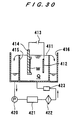
- FIG. 30 shows the general construction of a conventional plating apparatus for plating copper or the like on a semiconductor substrate.
- the conventional substrate plating apparatus is provided with a plating tank 411 that holds a plating liquid Q, and arranges a substrate W, such as a semiconductor wafer, and an anode 412 opposing each other therein.
- a plating power source 413 is connected to the substrate W and the anode 412. When the plating power source 413 applies a prescribed voltage thereacross, a current containing ions dissolved from the copper plate or the like serving as the anode 412 flows toward the surface (processing surface to be plated) of the substrate W and forms a plated copper film thereon.
- the substrate W is detachably held by a substrate holder 414.
- the anode 412 which is formed of copper containing phosphorus, for example
- the substrate W When the current flows between the anode 412, which is formed of copper containing phosphorus, for example, and the substrate W, the ionized copper is conveyed by the plating current and deposited on the surface of the substrate W to form a plated film.
- the plating liquid Q overflowing the wall 415 of the plating tank 411 is collected in a recovery tank 416.
- the plating liquid Q in the recovery tank 416 is reintroduced to the plating tank 411 through a plating liquid circulation system comprising a pump 420, a temperature regulating tank 421,a filter 422 and a flow meter 423 and so on.
- a plating liquid or a pretreatment liquid cannot enter deep inside of the trenches, plugs and openings, thereby leaving air bubbles therein. Such air bubbles can cause plating defects or incomplete plating.
- bumps electrically connect the semiconductor chip with substrate electrodes or TAB electrodes.
- electrolytic plating method vapor deposition method, printing method, and ball bump method.
- the electrolytic plating method has become in wide use due to its relatively stable performance and capability of forming fine connections, in view of the recent tendency to increasing number of I/O terminals on semiconductor chips and to finer pitch.
- the electrolytic plating method includes a spurting or cup method in which a substrate such as a semiconductor wafer is positioned horizontally with the processing surface to be plated facedown and a plating liquid is spurted from below; and a dipping method in which the substrate is placed vertically in a plating tank and immersed in a plating liquid, while a plating liquid is supplied from the bottom of the plating tank and is allowed to overflow the tank.
- a dipping method of electrolytic plating bubbles that can adversely affect the quality of the plating are easily removed and the footprint is small.
- the dipping method can be readily adapted to variations in wafer size. The dipping method is therefore considered to be suited for bump plating in which holes to be filling by the plating are relatively large and which requires a fairly long plating time.
- a seed layer 500 as an electric feed layer is first formed on the surface of the substrate W, as shown in FIG. 29A.
- a resist 502 having a height H of e.g. 20-120 ⁇ m is applied to the entire surface of the seed layer 500.
- An opening 502a having a diameter D of e.g. 20-200 ⁇ m is formed in a prescribed portion of the resist 502.
- Plating is performed onto such a surface of the substrate W to deposit and grow a plated film 504 in the opening 502a, thereby forming a bump 506 (see FIGS. 29B-29E).
- the air bubbles can escape easily.
- Conventional electrolytic plating apparatuses for the dipping method employ a substrate holder which holds a substrate sealing the edge and the backside thereof, such as a semiconductor wafer, while exposing the front surface (processing surface to be plated). Since such a substrate holder is immersed in the plating liquid with the substrate when plating the surface of the substrate, it is difficult to automate the entire plating process from loading of the substrate to unloading of the substrate after plating. Further, the plating apparatus occupies a considerably large space.
- the present invention has been made in view of the above drawbacks in the related art. It is therefore a first object of the present invention to provide a plating apparatus and method which enables a plating liquid entering into fine trenches and plugs for wiring and into openings of a resist formed in a substrate, without adding a surfactant to the plating liquid, and without suffering from plating defects and incomplete plating.
- a first embodiment of a plating apparatus comprises: a substrate holder capable of opening and closing for holding a substrate such that the front surface of the substrate is exposed while the back side and the edge thereof are hermetically sealed; a plating tank for holding a plating liquid in which an anode is immersed; a diaphragm provided in the plating tank and disposed between the anode and the substrate held by the substrate holder; plating liquid circulating systems for circulating the plating liquid through the respective regions of the plating tank partitioned by the diaphragm; and a deaerating unit provided in at least one of the plating liquid circulating systems.
- the diaphragm such as an ion exchange membrane or a neutral porous diaphragm, is disposed between the substrate and the anode, thereby preventing particles generated on the anode side from flowing through the diaphragm to the substrate side.
- At least one of the plating liquid circulating systems for circulating a plating liquid through the regions in the plating tank partitioned by the diaphragm is provided with a deaerating unit for removing gas from the plating liquid during the plating process. Accordingly, it is possible to maintain a low concentration of dissolved gases in the plating liquid, thereby reducing generation of gas bubbles in the plating liquid that can cause plating defects.
- the plating apparatus preferably further comprises a monitoring unit disposed downstream of the deaerating unit for monitoring the concentration of dissolved oxygen in the plating liquid.
- the plating liquid circulating system is provided with a unit for measuring and controlling dissolved gases. Accordingly, it is possible to maintain a uniform concentration of dissolved gas in the plating liquid so as to achieve a constant and stable high-quality plating process.
- the deaerating unit preferably comprises at least a deaerating membrane and a vacuum pump, the pressure on the decompressed side of the deaerating unit being controlled.
- a plating method comprising: providing a diaphragm between a substrate and an anode immersed in a plating liquid held in a plating tank; circulating the plating liquid in each region of the plating tank partitioned by the diaphragm; and plating the substrate while maintaining the concentration of dissolved oxygen in the plating liquid between 1 ⁇ g/l (1 ppb) and 4 mg/l (4 ppm) by a deaerating unit.
- a second embodiment of a plating apparatus comprises: a cassette table for loading a cassette housing a substrate therein; a substrate holder capable of opening and closing for holding the substrate such that the front surface of the substrate is exposed while the back side and the edge thereof are hermetically sealed; a substrate loading/unloading unit for supporting the substrate holder, and loading and unloading the substrate; a substrate transferring device for transferring the substrate between the cassette table and the substrate loading/unloading unit; a plating tank for accommodating the substrate holder and the substrate held vertically and facing to an anode, and plating the surface of the substrate by injecting a plating liquid from the bottom thereof; and a substrate holder transferring device having a transporter that grips the substrate holder and is vertically moveable, and transfers the substrate holder between the substrate loading/unloading unit and the plating tank.
- the plating tank may comprise a plurality of plating units accommodated in an overflow tank that accommodate electrodes for dummy plating, each unit being adapted for accommodating and plating one substrate.
- the overflow tank serves as a plating tank, thereby eliminating uneven plating between the plating units.
- This configuration also increases the surface of the electrodes for dummy plating, thereby improving efficiency of the dummy plating process. Further, since most of the plating liquid is circulated through the dummy electrolytic section, it is possible to facilitate formation of a uniform plating liquid state.
- Each plating unit is preferably provided with a paddle that is disposed between the anode and the substrate, and reciprocates to agitate the plating liquid.
- the paddle generates a uniform flow of plating liquid across the entire surface of the substrate, thereby enabling formation of a plated film having a uniform thickness over the entire surface of the substrate.
- a paddle drive device for driving the paddles is preferably provided on the opposite side of the substrate holder transferring device with respect to the plating tank. With this construction, it is possible to facilitate maintenance of the substrate holder transferring device and the paddle drive device.
- the plating apparatus may comprise plating tanks for performing different types of plating, wherein each plating tank comprises an overflow tank and plating units for performing each type of plating, the plating units being accommodated in the overflow tank.
- each plating tank comprises an overflow tank and plating units for performing each type of plating, the plating units being accommodated in the overflow tank.
- a local exhaust duct may be provided along one side of the plating tank.
- an air flow is generated in a single direction toward the local exhaust duct. Accordingly, a vapor emitted from the plating tanks can be carried on this air flow, thereby preventing the vapor from contaminating the semiconductor wafers and the like.
- a stocker for storing the substrate holder in a vertical position may be provided between the substrate loading/unloading unit and the plating tank; and the substrate holder transferring device may have first and second transporters. By performing transferring operations with separate transporters, the substrate holder can be transferred more smoothly, thereby increasing throughput.
- the substrate loading/unloading unit may preferably be provided with a sensor for checking the contact state between the substrate and contact points when the substrate is loaded into the substrate holder; and the second transporter selectively transfers only such substrate that has a good contact with the contact points to a subsequent process.
- the plating operation need not be halted but allows to be continuing, if a poor contact is detected between the substrate and contact points when the substrate is loaded into the substrate holder.
- the substrate in which the poor contact is detected does not apply to the plating process, but instead is discharged from the cassette after being returned thereto.
- the substrate holder transferring device may employ a linear motor as a means for moving the transporter.
- the transporter can be moved over a long distance and the overall length of the apparatus can be reduced. Further, parts such as long ball screws that require high-precision and maintenance can be eliminated.
- the plating apparatus may further comprises a pre-wetting tank, blowing tank, and cleaning tank between the stocker and the plating tank.
- a pre-wetting tank blowing tank, and cleaning tank between the stocker and the plating tank.
- the substrate should be placed in a pre-soaking tank after pre-wetting tank, wherein the oxide film on the seed layer is removed through chemical etching, before performing the plating operation.
- the substrate loading/unloading unit may be constructed to support two substrate holders side by side that are slidable laterally. With this construction, the apparatus requires only one mechanism for opening and closing the substrate holder and avoids the need to move the substrate transferring device laterally.
- a first embodiment of a plating apparatus for forming a protruding electrode concerns an apparatus for forming a protruding electrode on a substrate having wiring formed thereon, comprising: a cassette table for loading a cassette housing the substrate therein; a plating tank for plating the substrate; a cleaning unit for cleaning the plated substrate; a drying unit for drying the cleaned substrate; a deaerating unit for deaerating a plating liquid in the plating tank; a plating liquid regulating unit for analyzing the components of the plating liquid and adding components to the plating liquid based on the results of the analysis; and a substrate transferring device for transferring the substrate.
- a second embodiment of a plating apparatus for forming a protruding electrode according to the present invention concerns an apparatus for forming a protruding electrode on a substrate having wiring formed thereron comprising: a cassette table for loading a cassette housing the substrate therein; a pre-wetting tank for applying a pre-wetting treatment to the substrate to increase the wettability thereof; a plating tank for plating the substrate after the pre-wetting treatment; a cleaning unit for cleaning the plated substrate; a drying unit for drying the cleaned substrate; a deaerating unit for deaerating a plating liquid in the plating tank; and a substrate transferring device for transferring the substrate.
- a third embodiment of a plating apparatus for forming a protruding electrode according to the present invention concerns an apparatus for forming a protruding electrode on a substrate having wiring formed thereon comprising: a cassette table for loading a cassette housing the substrate therein; a pre-soaking tank for applying a pre-soaking treatment to the substrate; a plating tank for plating the substrate after the pre-soaking treatment; a cleaning unit for cleaning the plated substrate; a drying unit for drying the cleaned substrates; a deaerating unit for deaerating the plating liquid in the plating tank; and a substrate transferring device for transferring the substrates.
- a fourth embodiment of a plating apparatus for forming a protruding electrode according to the present invention concerns an apparatus for forming a protruding electrode on a substrate by plating the substrate with at least two kinds of metals, comprising: a plurality of plating tanks each for plating the substrate with each of the above metals; and a substrate transferring device for transferring the substrate, wherein the plating tanks are disposed along a transferring path of the substrate transferring device.
- a fifth embodiment of a plating apparatus for forming a protruding electrode concerns an apparatus for forming a protruding electrode on a substrate having wiring formed thereon, comprising: a cassette table for loading a substrate cassette thereon; a plating tank for plating the substrate; a cleaning unit for cleaning the plated substrate; a drying unit for drying the cleaned substrate; a deaerating unit for deaerating a plating liquid in the plating tank; an annealing unit for annealing the plated substrate; and a substrate transferring device for transferring the substrate.
- a first embodiment of a plating method for forming protruding electrodes concerns a method for forming a protruding electrode on a substrate having wiring formed thereon, comprising: holding a substrate taken out of a cassette by a substrate holder; pre-wetting the substrate held by the substrate holder; plating the pre-wetted surface of the substrate by immersing the substrate together with the substrate holder in a plating liquid; cleaning and drying the plated substrate together with the substrate holder; and taking the substrate out of the substrate holder and drying the substrate.
- a second embodiment of a plating method for forming a protruding electrode according to the present invention concerns a method for forming a protruding electrode on a substrate having wiring formed thereon, comprising: holding a substrate taken out of a cassette by a substrate holder; pre-soaking the substrate held by the substrate holder; plating the pre-soaked surface of the substrate by immersing the substrate together with the substrate holder in a plating liquid; cleaning and drying the substrate together with the substrate holder; and taking the substrate out of the substrate holder and drying the substrate.
- FIG. 1 shows the construction of a plating apparatus according to a first embodiment of the present invention.
- the plating apparatus includes a cation exchange membrane 318 as a diaphragm which is disposed between a cathode (substrate W) and an anode 312 connected to a plating power source 313.
- the cation exchange membrane (diaphragm) 318 partitioned the space in the plating tank 311 into two regions T 1 including the substrate W and T 2 including the anode 312.
- the plating apparatus of this embodiment is a copper-plating apparatus designed to form a plated copper film on the surface (processing surface to be plated) of the substrate W.
- the anode 312 is a soluble anode and a plating liquid Q is a copper sulfate solution.
- the substrate W which is detachably held by the substrate holder 314 with a watertight seal being made over the backside of the substrate W, is immerse in the plating liquid Q.
- the cation exchange membrane 318 only allows passage of Cu ions dissolved from the soluble anode 312, while blocking passage of impurities dissolved from the anode 312. This can minimize the amount of particles in the plating liquid Q in the substrate W side region T 1 partitioned by the cation exchange membrane 318.
- This embodiment employs a cation exchange membrane 318 disposed between the substrate W and the anode 312.
- a neutral porous diaphragm capable of removing small particles in place of the cation exchange membrane 318.
- the cation exchange membrane 318 having the capability of selectively filtering ions according to their electrical energy, can be a commercial product.
- One such example of the cation exchange membrane 318 is "Selemion” manufactured by Asahi Glass Co., Ltd.
- the neutral porous diaphragm is a porous membrane formed of synthetic resin and having extremely small holes of uniform diameter.
- One such example is a product called "YUMICRON” manufactured by Yuasa Ionics Co., Ltd., which is composed of a polyester nonwoven fabric as a base material and of polyvinylidene fluoride and titanium oxide as a membrane material.
- the deaerator 328 removes dissolved gases from the plating liquid Q flowing through the first plating liquid circulation system C 1 .
- the deaerator 328 is provided with a vacuum pump 329 for removing various dissolved gases including oxygen, air, and carbon dioxide and the like from the plating liquid Q flowing through the circulation system using a membrane which allows only gases to pass therethrough, while preventing the passage of liquid.
- the vacuum pump 329 removes dissolved gases from the plating liquid by drawing the gases through the membrane in the deaerator 328.
- the dissolved oxygen concentration measuring unit 340 is provided in the first plating liquid circulation system C 1 to monitor the concentration of dissolved oxygen in the plating liquid circulating through the first plating liquid circulation system C 1 .
- the flow meter 323 measures the flow of the plating liquid Q circulating through the first plating liquid circulation system C 1 and transmits a signal representing this flow to a control unit (not shown).
- the control unit maintains the amount of plating liquid Q circulating through the first plating liquid circulation system C 1 at a fixed prescribed amount by controlling the speed of the vacuum pump 320, for example, thereby achieving stable plating in the plating tank 311.
- a second plating liquid circulation system C 2 is provided on the anode 312 side of the plating tank 311 partitioned by the cation exchange membrane 318.
- the second plating liquid circulation system C 2 circulates the plating liquid Q overflowing the plating tank 311 back to the region T 2 on the anode side of the plating tank 311 by the pump 320 through the temperature regulating unit 321, filter 322, and flow meter 323.
- the flow meter 323 measures the flow of the plating liquid Q circulating through the second plating liquid circulation system C 2 and transmits a signal representing this flow to a control unit (not shown).
- the control unit maintains the amount of plating liquid Q circulating through the second plating liquid circulation system C 2 at a fixed rate by controlling the speed of the vacuum pump 320 or the like.
- FIG. 2 shows a plating apparatus according to a second embodiment of the present invention.
- the second plating liquid circulation system C 2 disposed on the anode 312 side of the plating tank 311 partitioned by the cation exchange membrane 318 is further provided with the deaerator (deaerating device) 328 and dissolved oxygen concentration measuring unit 340. Accordingly, the plating liquid Q is deaerated while being circulated to both the regions T 1 on the substrate W (anode) side and T 2 on the anode 312 side partitioned by the cation exchange membrane 318. Therefore, it is possible to further reduce the amount of gas bubbles in the plating liquid compared to the first embodiment shown in FIG. 1.
- the embodiments described above show copper plating on the surface of a semiconductor wafer.
- the object of the plating is not limited to semiconductor wafers.
- the present invention can also be applied to other types of substrates.
- plating metal other than copper can be used in the anode.
- the deaerator and dissolved oxygen concentration measuring unit are disposed in the circulating paths of the plating liquid in the embodiments described above, these units can also be disposed in the plating tank itself. In this way, many variations to the embodiments can be made without departing from the scope of the invention.
- the plating apparatuses of the above embodiments can provide optimal plating conditions, due to the provision of a deaerator (deaerating unit) 328 in at least one of the circulation systems C 1 and C 2 partitioned by the cation exchange membrane (diaphragm) 318 for deaerating the plating liquid Q prior to the plating process or during the plating process.
- a deaerator (deaerating unit) 328 in at least one of the circulation systems C 1 and C 2 partitioned by the cation exchange membrane (diaphragm) 318 for deaerating the plating liquid Q prior to the plating process or during the plating process.
- the dissolved oxygen concentration measuring unit 340 provided in 'the circulation systems C 1 and C 2 for controlling dissolved gases in the plating liquid can reduce the amount of dissolved gases in the plating liquid in the plating tank. Accordingly, there is less chance for air bubbles to be attached on the surface of the substrate (processing surface to be plated), thereby achieving a stable plating process.
- FIG. 3A shows the overall construction of a plating apparatus according to a third embodiment of the present invention.
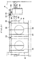
- the plating apparatus is provided with two cassette tables 12 for placing thereon cassettes 10 that house substrates W, such as semiconductor wafers; an aligner 14 for aligning the orientation flat or notch, etc. of the substrate W in a prescribed direction; and a spin dryer 16 for spin drying the substrate at a high rotation speed after the plating process, all arranged along the same circle.
- a substrate loading/unloading unit 20 for placing the substrate holders 18 thereon, which detachably hold the substrates, is provided along a tangent line to the circle.
- a substrate transferring device 22, such as a transferring robot, is disposed in the center of these units for transferring substrates W therebetween.
- a resist peeling unit 600 for peeling the resist 502 (see FIGS. 29A-29E) off from the surface of the substrate; a seed layer removing unit 602 for removing the unneeded seed layer 500 (see FIGS. 29A-29E) after the plating process; a heating unit 604 for heating the plated substrate.
- a reflowing unit 606 for causing a plated film 504 (see FIGS. 29B-29D) to reflow and an annealing unit 608 for annealing the substrate after reflowing may be provided in place of the heating unit 604.
- a stocker 24 Disposed in a line that proceeds away from the substrate loading/unloading unit 20 are in order a stocker 24 for keeping and temporarily placing the substrate holders 18; a pre-wetting tank 26 holding pure water in which the substrate W is immersed to make the surface of the substrate more hydrophilic; a pre-soaking tank 28 holding a sulfuric acid or hydrochloric acid solution or the like for etching the surface of the seed layer formed on the surface of the substrate W in order to remove the oxidized layer having a high electrical resistance; a first cleaning tank 30a holding pure water for cleaning the surface of the substrate; a blowing tank 32 for removing water from the substrate after the cleaning process; a second cleaning tank 30b; and a copper plating tank 34.
- the copper plating tank 34 includes an overflow tank 36 and a plurality of copper plating units 38 accommodated in the overflow tank 36.
- Each copper plating unit 38 accommodates one substrate W and performs a plating process on the substrate W.
- copper plating is described as an example in this embodiment, the same description naturally holds for nickel, solder, or gold plating.
- a substrate holder transferring device (substrate transferring device) 40 is provided along the side of the units for transferring the substrate holders 18 with substrates W to each unit.
- the substrate holder transferring device 40 includes a first transporter 42 for transferring substrates W between the substrate loading/unloading unit 20 and stocker 24, and a second transporter 44 for transferring substrates W between the stocker 24, pre-wetting tank 26, pre-soaking tank 28, cleaning tanks 30a and 30b, blowing tank 32, and copper plating tank 34.
- a plurality of paddle driving units 46 are disposed on the opposite side of the substrate holder transferring device 40 with respect to the overflow tank 36.
- the paddle driving units 46 drive paddles 202 (see FIGS. 20 and 21) positioned in each of the plating units 38 and serving as stirring rods for agitating the plating liquid.
- the substrate loading/unloading unit 20 is provided with a flat shaped loading plate 52 capable of sliding horizontally along rails 50.
- the loading plate 52 supports two of substrate holders 18 side by side in a level state. After the substrate W is transferred between one of the substrate holders 18 and the substrate transferring device 22, the flat loading plate 52 is slid in a horizontal direction, and then the substrate W is transferred between the other substrate holder 18 and the substrate transferring device 22.
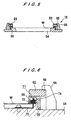
- the substrate holder 18 includes a flat, rectangular shaped fixed supporting member 54, and a ring-shaped moveable supporting member 58 mounted on the fixed supporting member 54 and capable of opening and closing over the fixed supporting member 54 through a hinge 56.
- a ring-like seal packing 60 having a rectangular cross-section with an open bottom with one of the parallel sides longer than the other, is mounted at the fixed supporting menber54 side of the moveable supporting member 58 through a packing base 59 made of vinyl chloride, serving as a reinforcing member and having a good lubrication with a clamp ring 62.
- the clamp ring 62 is held on the fixed supporting menber54 via bolts 64 passing through a plurality of long holes 62a formed along the circumference of the clamp ring 62 so as to be rotatable and not be removed from the fixed supporting member 54.
- Pawls 66 shaped roughly like a upside-down letter L are arranged at regular intervals around the periphery of the moveable supporting member 58 and mounted on the fixed supporting member 54.
- a plurality of protrusions 68 are integrally formed at intervals equivalent to those of the pawls 66 on the outer surface of the clamp ring 62.
- Slightly elongated holes 62b are formed in e.g. three locations in the clamp ring 62, as shown, for rotating the clamp ring 62.
- the top surface of the protrusions 68 and the bottom surface of the pawls 66 are tapered in the rotating direction in opposing directions from each other.
- conductors (electrical contact points) 70 connected to an external electrode (not shown) are disposed on the fixed supporting member 54.
- the edges of the conductors 70 are exposed on the surface of the fixed supporting member 54 at outer side of the substrate W.
- Depressions 71 are formed inside the moveable supporting member 58 through the seal packing 60 at a position facing the exposed portion of the conductors 70.
- Ametal armature 72 is accommodated in each of the depressions 71.
- Each of the metal armature 72 has a rectangular cross-section with an open bottom.
- a spring 74 presses each of the metal armatures 72 against the fixed supporting member 54.
- At least one of the contacting surface of the conductor 70 which contacts the metal armature 72, the contacting surface of the metal armature 72 which contacts the conductor 70, and the contacting surface of the metal armature 72 which contacts the substrate W is preferably coated with a metal such as gold or platinum by plating.
- the conductor 70 and the metal armature 72 may be made of stainless steal which has an excellent corrosion resistance.
- the moveable supporting member 58 is opened and closed by a cylinder (not shown) and the weight of the moveable supporting member 58 itself.
- a through-hole 54a is formed in the fixed supporting member 54.
- the cylinder is provided at a position facing the through-hole 54a when the substrate holder 18 is mounted on the loading plate 52.
- the moveable supporting member 58 is opened by extending a cylinder rod (not shown) to push the moveable supporting member 58 upward through the through-hole 54a. By retracting the cylinder rod, the moveable supporting member 58 closes by its own weight.
- the moveable supporting member 58 is locked and unlocked by rotating the clamp ring 62.
- a locking/unlocking mechanism is provided on the ceiling side.
- the locking/unlocking mechanism has pins disposed at positions corresponding to the holes 62b of the substrate holder 18 placed on the loading plate 52 and positioned its center side. In this state, when the loading plate 52 is raised, the pins enter the holes 62b.
- the clamp ring 62 is rotated by rotating the pins around the axial center of the clamp ring 62. Since only one locking/unlocking mechanism is provided, after locking (or unlocking) one of the substrate holders 18 placed on the loading plate 52, the loading plate 52 is slid horizontally in order to lock (or unlock) another substrate holder 18.
- the substrate holder 18 is provided with a sensor for checking that the substrate W is electrically connected to a contact points when the substrate W is loaded into the substrate holder 18. Signals from the sensor are input to a controller unit (not shown).
- a pair of hands 76 integrally formed on the end of the fixed supporting member 54 of the substrate holder 18 and shaped approximately like the letter T, serve as supports when transferring the substrate holder 18 and when holding the same in a suspended state.
- the transporter 42 of the substrate holder transferring device 40 grips the hands 76 of the substrate holder 18 in the suspended state and transfers the substrate holder 18.
- the substrate holder 18 is also held in a vertically suspended state on the surrounding walls of the pre-wetting tank 26, pre-soaking tank 28, cleaning tanks 30a, 30b, blowing tank 32, and copper plating tank 34.
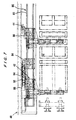
- FIGS. 7 and 8 show a linear motor unit 80 serving as the transport section of the substrate holder transferring device 40.
- the linear motor unit 80 mainly comprises a lengthy base 82 and two sliders 84, 86 that are capable of sliding along the base 82.
- the transporters 42 and 44 are mounted on top of the sliders 84 and 86, respectively.
- a cable conveyer bracket 88 and a cable conveyer receiver 90 are provided on the side of the base 82.
- a cable conveyer 92 extends along the cable conveyer bracket 88 and cable conveyer receiver 90.
- these transporters 42, 44 can be moved over a long distance and the overall length of the apparatus can be shortened by shortening the length of the transporters 42, 44. Further, devices that require high-precision and maintenance, such as long ball screws, can be eliminated.
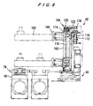
- FIGS. 9 through 12 show the transporter 42.
- the transporter 42 mainly comprises a transporter body 100, an arm 102 protruding horizontally from the transporter body 100, an arm raising/lowering mechanism 104 for raising and lowering the arm 102, an arm rotating mechanism 106 for rotating the arm 102, and gripping mechanisms 108 provided in the arm 102 for gripping and releasing the hands 76 of the substrate holder 18.
- the raising/lowering mechanism 104 includes a rotatable ball screw 110 extending vertically and a nut 112 that engages with the ball screw 110; a linear motor base 114 is connected to the nut 112.
- a timing belt 122 is looped around the drive pulley 118 fixed to the drive shaft of the raising/lowering motor 116 mounted on the transporter body 100 and a follow pulley 120 fixed to the top end of the ball screw 110.
- the raising/lowering motor 116 drives the ball screw 110 to rotate.
- the rotation of the ball screw 110 raise and lower the linear motor base 114 connected to the nut 112, engaging with the ball screw 110, along a linear motor guide.
- the arm rotating mechanism 106 includes a sleeve 134 that rotatably accommodates a rotating shaft 130 and fixed to the linear motor base 114 via a mounting base 132, and a rotating motor 138 fixed to the end of the sleeve 134 via a motor base 136.
- a timing belt 144 looped around a drive pulley 140 fixed to the drive shaft of the rotating motor 138 and a follow pulley 142 fixed to the end of the rotating shaft 130.
- the rotating motor 138 drives the rotating shaft 130 to rotate.
- the arm 102 is linked to the rotating shaft 130 through a coupling 146 and therefore raises and lowers and rotates together with the rotating shaft 130.
- the arm 102 includes a pair of side plates 150 that are coupled with the rotating shaft 130 and rotate together with the same.
- the gripping mechanisms 108 are disposed between the side plates 150, 150. Two gripping mechanisms 108 are provided in this example. However, only a description of one will be given, as both have the same construction.
- the gripping mechanism 108 includes a fixed holder 152, the end of which is accommodated between the side plates 150, 150 and is capable of moving freely in the widthwise direction; guide shafts 154 penetrating through the inner portion of the fixed holder 152; and a moveable holder 156 connected to one end (the bottom end in FIG. 12) of the guide shafts 154.
- a cylinder 158 for movement in the widthwise direction is mounted on one of the side plates 150.
- the fixed holder 152 is coupled to the cylinder 158 through a cylinder joint 160.
- a shaft holder 162 is mounted on the other end (the upper end in FIG. 12) of the guide shafts 154.
- the shaft holder 162 is coupled to a cylinder 166 for vertical movement through a cylinder connector 164.
- the fixed holder 152 together with the moveable holder 156 moves in the widthwise direction between the side plates 150, 150 with the operations of the cylinder 158. Further, the moveable holder 156 moves up and down, while being guided by the guide shafts 154 with the operations of the cylinder 166.
- the moveable holder 156 can be lowered to below of the hands 76 while avoiding interference with the hands 76.
- the cylinder 158 is operated to position the fixed holder 152 and moveable holder 156 above and below the hands 76, thereby interposing the hands 76 between the fixed holder 152 and moveable holder 156.
- the cylinder 166 is operated to grip the hands 76 between the fixed holder 152 and moveable holder 156. The grip is released by performing this operation in reverse.
- a depression 76a is formed on one of the hands 76 of the substrate holder 18.
- a protrusion 168 for engaging the depression 76a is provided on the moveable holder 156 at a position corresponding to the depression 76a, enabling a more reliable grip.
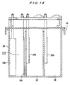
- FIGS. 13 through 16 shows a copper plating tank 34 accommodating four copper plating units 38 in two rows.
- the copper plating tank 34 accommodating eight plating units 38 in two rows, shown in FIG. 3A, has essentially the same construction.
- the construction of the copper plating tank 34 is the same when increasing the number of copper plating units.
- the copper plating tank 34 is provided with an overflow tank 36 formed in a rectangular box shape with an open top.
- the overflow tank 36 includes the tops of peripheral walls 170 that protrude higher than the tops 180 of peripheral walls 172 on each of the plating units 38 accommodated in the overflow tank 36.
- a plating liquid channel 174 is formed around the plating units 38 when the plating units 38 are accommodated in the overflow tank 36.
- a pump inlet port 178 is provided in the channel 174. With this construction, a plating liquid that overflows the plating units 38 flows into the channel 174 and is discharged through the pump inlet port 178.
- the overflow tank 36 is provided with a liquid leveler (not shown) for maintaining the plating liquid in each of the plating units 38 at a uniform level.
- insertion grooves 182 are provided on the inner side surfaces of the plating units 38 for guiding the substrate holder 18.
- a plating liquid circulation system C 3 is provided for circulating the plating liquid Q which overflows the plating units 38 and collects in the overflow tank 36 with the vacuum pump 320.
- the vacuum pump 320 circulates the plating liquid Q through a temperature regulating unit 321, a filter 322, a deaerator (deaerating unit) 328, a dissolved oxygen concentration measuring unit 340, and a flow meter 323 back to inside of the copper plating units 38.
- the deaerator 328 is provided with a vacuum pump 329 for removing various dissolved gases, including oxygen, air, and carbon dioxide, from the plating liquid Q flowing through the circulation system using a membrane.
- the membrane allows only gases to pass therethrough, while preventing the passage of liquid.
- a plating liquid regulating unit 610 is further provided in a branch off the plating liquid circulation system C 3 for analyzing the plating liquid while one-tenth of the overall plating liquid, for example, is extracting. Based on the analysis results, components that are lacking in the plating liquid are added to the plating liquid.
- the plating liquid regulating unit 610 includes a plating liquid regulating tank 612 in which components lacking in the solution are added.
- a temperature controller 614 and a plating liquid analyzing unit 616 for extracting and analyzing a sample of plating liquid are disposed adjacent to the plating liquid regulating tank 612. The plating liquid returns from the plating liquid regulating tank 612 to the plating liquid circulation system C 3 through a filter 620 by the operation of a pump 618.
- the plating apparatus of the present invention employs both a feedforward control method for predicting disturbances based on the processing time and the number of substrates plated and adding components to be needed, and a feedback control method for analyzing the plating liquid and adding components that are lacking in the plating liquid based on the results on that analysis.
- a feedforward control method for predicting disturbances based on the processing time and the number of substrates plated and adding components to be needed
- a feedback control method for analyzing the plating liquid and adding components that are lacking in the plating liquid based on the results on that analysis.
- the plating liquid regulating unit 610 is disposed in a housing 609, for example, that accommodates the cassette tables 12, substrate loading/unloading unit 20, stocker 24, pre-wetting tank 26, pre-soaking tank 28, cleaning tanks 30a, 30b, and copper plating tank 34.
- the plating liquid regulating unit 610 can also be positioned outside the housing 609, as shown in FIG. 3E.
- the pre-wetting tank 26 is provided with a pure water circulation system C 4 which collects the pure water that has overflowed the pre-wetting unit 26a in the overflow tank 26b, and returns the pure water to inside the pre-wetting unit 26a through a temperature regulating unit 321, a filter 322, a deaerator (deaerating unit) 328, and a flow meter 323 by a vacuum pump 320.
- the deaerator 328 is provided with a vacuum pump 329 for removing various dissolved gases, including oxygen, air, and carbon dioxide, from the pure water flowing through the circulation system using a membrane. The membrane allows only gases to pass therethrough, while preventing the passage of liquid.
- a pure water tank 330 for supplying the pure water to the pure water circulation system C 4 is provided.
- a plating cathode 184 and an anode 186 for dummy plating are disposed in the plating liquid channel 174.
- the anode 186 can be formed of a titanium basket, for example, in which copper chips or the like are inserted.
- the overflow tank 36 can serve as a plating tank, thereby not only eliminating uneven plating in the plating units 38, but also increasing the surface of the dummy electrode for improving the efficiency of dummy plating. Further, by circulating most of the plating liquid through the dummy plating section, it is possible to facilitate formation of a uniform plating liquid.
- FIG. 17 shows a cross-sectional view of the copper plating unit 38.
- an anode 200 is disposed in the plating unit 38 at a position facing the surface of the substrate W when the substrate holder 18 holding the substrate W is disposed along the insertion grooves 182 (see FIGS. 13 and 15).
- the paddle 202 is positioned substantially vertical between the anode 200 and substrate W.
- the paddle 202 can reciprocate in a direction parallel to the substrate W by the paddle driving unit 46, which will be described in more detail below.
- a uniform flow of plating liquid can be created across the entire surface of the substrate W, thereby forming a plated film with a uniform thickness over the entire surface of the substrate W.
- a regulation plate 204 (mask) formed with a center hole 204a that corresponds to the size of the substrate W is provided between the substrate W and the anode 200.
- the regulation plate 204 lowers an electrical potential around the periphery of the substrate W, thereby achieving an even more uniform thickness of the plated film.
- FIG. 18 shows a cross-section of the portion of the plating apparatus in which the copper plating tank 34 is disposed.
- FIG. 19 shows a more detailed view of the plating liquid injecting portion of FIG. 18.
- the plating liquid is supplied to the plating units 38 through plating liquid supply pipes 206 disposed lower the plating units 38.
- the plating liquid that overflows the overflow tank 36 is discharged through a plating liquid discharge pipe 208 disposed at the lower part.
- the plating liquid supply pipes 206 are opened inside the plating units 38 at the bottom of them.
- a regulating plate 210 is mounted at the open end of the plating liquid supply pipe 206. The plating liquid is injected through the regulating plate 210 into the plating unit 38.
- a waste solution pipe 212 is attached at one open end to the plating unit 38 and positioned around the plating liquid supply pipe 206, while the other end of the waste solution pipe 212 is connected to the plating liquid discharge pipe 208 through an elbow pipe 214. With this configuration, the plating liquid near the plating liquid supply pipe 206 is discharged through the waste solution pipe 212 and plating liquid discharge pipe 208, and prevented the plating liquid from being stagnant at this point.
- FIGS. 20 and 21 show the paddle driving units 46.
- a plurality of paddle driving units 46 are provided.
- FIGS. 20 and 21 show only two paddle driving units 46, each of the paddle driving units 46 has the same construction. Therefore, duplicate descriptions of this part will be omitted by designating the same reference number.
- the paddle driving unit 46 is provided with a paddle drive motor 220, a crank 222 coupled to a drive shaft of the paddle drive motor 220, a cam follower 224 mounted on the far end of the crank 222, and a slider 228 having a grooved cam 226 in which the cam follower 224 slides.
- a paddle shaft 230 is coupled to the slider 228 and disposed across the copper plating tank 34.
- the paddle 202 is vertically attached at prescribed locations along the length of the paddle shaft 230.
- a shaft guide 232 supports the paddle shaft 230 and only allows the paddle shaft 230 to reciprocate in the lengthwise direction.
- the drive of the paddle drive motor 220 rotates the crank 222.
- the rotating movement of the crank 222 is converted into linear movement in the paddle shaft 230 by the slider 228 and the cam follower 224.
- the paddle 202 attached vertically to the paddle shaft 230 reciprocates in a direction parallel to the substrate W.
- Different diameters of substrates W can be easily handled by adjusting the mounting position of the paddle 202 on the paddle shaft 230 to a desirable position. Since the paddle 202 reciprocates constantly during the plating process, this movement has generated wear in the mechanical parts and has caused the generation of particles through the mechanical sliding. In this example, however, the construction of the paddle support units has been improved, thereby improving the durability of the mechanism and greatly reducing the occurrence of such problems.
- a plating process will be described for plating a series of bump electrodes using the plating apparatus of the embodiments described above.
- a seed layer 500 as an electric feed layer is formed on the surface of a substrate.
- a resist 502 having a height H of e.g. 20-120 ⁇ m is applied over the entire surface of the seed layer 500.
- an opening 502a having a diameter D of e.g. 20-200 ⁇ m is formed at a prescribed position in the resist 502.
- Such a substrate W is inserted in the cassette 10 described above with the surface (processing surface to be plated) facing upward.
- the cassette 10 is loaded onto the cassette table 12.
- the substrate transferring device 22 takes out one substrate from the cassette 10 on the cassette table 12 and places the substrate on the aligner 14.
- the aligner 14 aligns the orientation flat or notch or the like in the prescribed orientation.
- the substrate transferring device 22 transfers the aligned substrate W to the substrate loading/unloading unit 20.
- the substrate loading/unloading unit 20 two substrate holders 18 accommodated in the stocker 24 are gripped by the gripping mechanisms 108 of the transporter 42 of the substrate holder transferring device 40 simultaneously.
- the arm raising/lowering mechanism 104 raises the arm 102
- the arm 102 is moved to the substrate loading/unloading unit 20.
- the arm rotating mechanism 106 rotates the arm 102 at 90° to hold the substrate holders 18 in a horizontal state.
- the arm raising/lowering mechanism 104 lowers the arm 102, placing both substrate holders 18 on the loading plate 52 simultaneously.
- the cylinders are operated to open the moveable supporting members 58 of the substrate holders 18.
- the substrate transferring device 22 inserts the substrate into one of the substrate holders 18 positioned in the center of the substrate loading/unloading unit 20.
- the cylinder performs a reverse operation to close the moveable supporting member 58.
- the moveable supporting member 58 is locked by the locking/unlocking mechanism.
- the loading plate 52 is slid horizontally to load another substrate in the other substrate holder 18. Subsequently, the loading plate 52 is returned to its original position.
- each of the surfaces of the substrates to be plated is exposed in the opening portion of the substrate holder 18.
- the seal packing 60 seals the peripheral portion of the substrates W to prevent the plating liquid from entering thereinto. Electricity is continued through the plurality of contact points in areas not in contact with the plating liquid. Wiring is connected from the contact points to the hands 76 of the substrate holder 18. By connecting a power source to the hands 76, electricity can be supplied to the seed layer 500 formed on the substrate.
- the gripping mechanisms 108 of the transporter 42 of the substrate holder transferring device 40 grip both of the substrate holders 18 holding the substrate simultaneously, and the arm raising/lowering mechanism 104 raises the arm 102.
- the arm rotating mechanism 106 rotates the arm 102 by 90° , such that the substrate holders 18 are positioned vertically.
- the arm raising/lowering mechanism 104 lowers the arm 102, thereby suspending (temporarily placement) the two substrate holders 18 in the stocker 24.
- the above process performed by the substrate transferring device 22, the substrate loading/unloading unit 20, and the transporter 42 of the substrate holder transferring device 40 is repeated in order to load substrate W one after another into the substrate holder 18 accommodated in the stocker 24 and suspend (temporarily placement) the substrate holder 18 one after another at prescribed positions in the stocker 24.
- the sensor When the sensor mounted on the substrate holder 18 for checking the contact state between the substrate and the contact points determines a poor contact, the sensor inputs the signal into a controller (not shown).
- the gripping mechanisms 108 of the other transporter 44 of the substrate transferring device 40 simultaneously grip two substrate holders 18 that have been holding the substrates and temporarily placed in the stocker 24.
- the arm raising/lowering mechanism 104 of the transporter 44 raises the arm 102 and the transporter 44.transfers the substrate holders 18 to the pre-wetting tank 26.
- the arm raising/lowering mechanism 104 lowers the arm 102, thereby immersing the both substrate holders 18 into pure water, for example, held in the pre-wetting tank 26.
- the pure water wets the surfaces of the substrates W to create a more hydrophilic surface.
- an aqueous liquid other than pure water can be used, providing the liquid can improve the hydrophilic property of the substrate by wetting the surface of the substrate and replacing the bubbles in the holes with water.
- the substrate holder 18 holding the substrate having the poor contact is left stored in the stocker 24. Accordingly, when a poor contact between a substrate and the contact points of the substrate holder 18 occurs, it does not halt the apparatus, but allows plating operations to continue. The substrate with a poor contact does not apply to the plating process. Instead the substrate is returned to the cassette and discharged from the cassette.
- the substrate holders 18 holding the substrates are transferred in the same way as described above to the pre-soaking tank 28 and the substrates are immersed into a chemical liquid such as sulfuric acid or hydrochloric acid held in the pre-soaking tank 28.
- the chemical liquid etches an oxide layer having a high electrical resistance that is formed on the surface of the seed layer and exposes a clean metal surface.
- the substrate holders 18 holding the substrates are transferred in the same way to the cleaning tank 30a, wherein the surfaces of the substrates are cleaned by pure water held therein.
- the substrate holders 18 holding the substrates are transferred in the same way as described above to the copper plating tank 34, which is filled with a plating liquid, and suspended in the plating units 38.
- the transporter 44 of the substrate holder transferring device 40 repeatedly performs this operation of transferring the substrate holder 18 to the plating unit 38 and suspending the substrate holder 18 at a prescribed position therein.
- plating liquid is supplied through the plating liquid supply pipes 206. While the plating liquid overflows into the overflow tank 36, plating voltages are applied between the anodes 200 and the substrates.
- the paddle driving units 46 reciprocate the paddles 202 in a direction parallel to the surfaces of the substrates, thereby plating the surfaces of the substrates.
- each of the substrate holders 18 is fixed in a suspended state by the hands 76 at the top of the plating unit 38. Electricity is supplied from a plating power source to the seed layer on the substrate via the hand fixed portion, the hand, and the contact points.
- the plating liquid is injected into the plating units 38 through the bottom thereof and overflows into the top of the walls around the plating units 38.
- the overflowed plating liquid is regulated of its concentration, and removed of foreign body by the filter before being reintroduced into the plating units 38 from the lower portion of the plating units 38. With this circulation process, the concentration of the plating liquid is maintained at a constant level.
- the plating liquid can be maintained at an even more uniform state by applying a dummy electrolytic voltage between the cathode 184 and the anode 186 for dummy plating.
- the gripping mechanisms 108 of the transporter 44 of the substrate holder transferring device 40 grip two of the substrate holders 18 holding the substrates simultaneously, and transfer the substrate holders 18 to the cleaning tank 30b, as described above.
- the substrate holders 18 are immersed in pure water held in the cleaning tank 30b to clean the surfaces of the substrates W.
- the substrate holders 18 are transferred as described above to the blowing tank 32, where air is blown onto the substrate holders 18 holding the substrates to remove water droplets deposited thereon.
- the substrate holders 18 are returned and suspended at prescribed positions in the stocker 24, as described above.
- the gripping mechanisms 108 of the transporter 42 of the substrate holder transferring device 40 simultaneously grip two of the substrate holders 18 holding the substrates that have been returned to the stocker 24 after the plating process, and place the substrate holders 18 on the loading plate 52 of the substrate loading/unloading unit 20, as described above.
- a substrate for which a poor connection was detected by the sensor mounted on the substrate holders 18 for checking contact state between the substrate and contact points and which was left in the stocker 24 is also transferred to the loading plate 52.
- the moveable supporting member 58 in the substrate holder 18 positioned at the center of the substrate loading/unloading unit 20 is unlocked by the locking/unlocking mechanism.
- the cylinder is operated to open the moveable supporting member 58.
- the substrate transferring device 22 takes the plating processed substrate out of the substrate holder 18 and transfers the substrate to the spin dryer 16.
- the spin dryer 16 spins the substrate at a high rotation speed for spin drying (draining).
- the substrate transferring device 22 then transfers the substrate back to the cassette 10.
- the loading plate 52 is slid laterally, and the same process is performed for the substrate mounted in the other substrate holder 18 so that the substrate is spin-dried and returned to the cassette 10.
- the loading plate 52 is returned to its original position.
- the gripping mechanisms 108 of the transporter 42 grip two substrate holders 18 which now contain no substrate, at the same time, and return the substrate holders 18 to the prescribed position in the stocker 24, as described above.
- the gripping mechanisms 108 of the transporter 42 of the substrate holder transferring device 40 grip two of the substrate holders 18 holding the substrates that have been returned to the stocker 24 after the plating process, and transfers the substrate holders 18 onto the loading plate 52, as described above. The same process is repeated.
- the process is completed when all substrates have been taken out of the substrate holders, which have been holding substrates after the plating process and returned to the stocker 24, spin-dried and returned to the cassette 10.
- This process provides substrates W that have a plated film 504 grown in the opening 502a formed in the resist 502, as shown in FIG. 29B.
- the substrate W is spin dried, as described above, and transferred to the resist peeling unit 600.
- the substrate W is immersed in a solvent, such as acetone, that is maintained at a temperature of 50-60°C, for example.
- the resist 502 is peeled off from the surface of the substrate W, as shown in FIG. 29C.
- the substrate W is transferred to the seed layer removing unit 602 where the unnecessary seed layer 500 exposed after the plating process is removed, as shown in FIG. 29D.
- the substrate W is transferred to the heating unit 604 comprising e.g.
- the substrate W is annealed at a temperature of, for example, 100°C or higher, thereby removing residual stress in the bump 506. This annealing process helps to form an alloy in the bump 506 when forming a bump by multi-layer plating, as described below. After the annealing process, the substrate W is returned to the cassette 10 to complete the process.
- the plated film 504 is caused to reflow in the reflowing unit 606, and then the substrate is transferred to the annealing unit 608 and annealed therein.
- the stocker 24 for accommodating the substrate holders 18 in a vertical position is provided between the substrate loading/unloading unit 20 and plating units 38.
- the first transporter 42 of the substrate holder transferring device 40 transfers the substrate holders 18 between the substrate loading/unloading unit 20 and stocker 24, and the second transporter 44 of the substrate holder transferring device 40 transfers the substrate holders 18 between the stocker 24 and plating units 38, respectively.
- Unused substrate holders 18 are stored in the stocker 24. This is designed to improve throughput by providing smooth transferring of the substrate holders 18 on either side of the stocker 24. However, it is of course possible to use one transporter to perform all transferring operations.
- a robot having a dry hand and a wet hand may be employed as the substrate transferring device 22.
- the wet hand is used only when taking out plating-processed substrates from the substrate holders 18.
- the dry hand is used for all other operations.
- the wet hand is not necessarily required since the backside of the substrate does not contact with plating liquid due to the seal of the substrate holder 18.
- a bar code may be attached to the cassette 10.
- the substrate taken out of the cassette 10 before a plating process can be returned to the same cassette 10 after the plating process, and the processing state of the substrate W and the state of the substrate holder 18 can be monitored.
- the substrate itself may be managed.
- FIGS. 22A and 23 show a plating apparatus according to a fourth embodiment of the present invention.
- This apparatus is provided with plating tanks for performing different types of plating processes and adapted to various processes freely.
- FIG. 22A shows a plating section provided with plating tanks for performing various types of plating processes.
- the plating section includes the stocker 24; a temporary storing platform 240; the pre-wetting tank 26; the pre-soaking tank 28; the first cleaning tank 30a; a nickel plating tank 244 having an overflow tank 36a and a plurality of nickel plating units 242 disposed in the overflow tank 36a for performing nickel plating on the surface of a substrate; the second cleaning tank 30b; the copper plating tank 34 having the overflow tank 36 and a plurality of the copper plating units 38 disposed in the overflow tank 36 for performing copper plating on the surface of a substrate; the third cleaning tank 30c; the blowing tank 32; the fourth cleaning tank 30d; and a solder plating tank 248 having an overflow tank 36b and a plurality of solder plating units 246 disposed in the overflow tank 36b for performing solder plating on the surface of a substrate.
- the constructions of the nickel plating units 242 and the solder plating units 246 are essentially the same as that of the copper plating units 38. Further, the constructions of the nickel plating tank 244 and solder plating tank 248 accommodating the respective units in the respective overflow tanks have essentially the same construction as the copper plating tank 34. All other constructions are the same as these described in the first embodiment.
- the substrate mounted in the substrate holder 18 applied to nickel plating, copper plating, and solder plating in order on its surface.
- this apparatus can perform a series of operations to form bump electrodes and the like with multiple plating: nickel, copper, and solder.
- the plating apparatus includes four nickel plating units 242, four copper plating units 38, and fourteen solder plating units 246 (22 plating units in total).
- the apparatus can comprise four nickel plating units 242, four copper plating units 38, and eighteen solder plating units 246 (26 plating units in total).
- the number of each type of plating units can be set arbitrarily.
- the kind of metal to be plated in each unit can also be varied.
- Ni-Cu-solder multi-layer bumps In addition to the Ni-Cu-solder multi-layer bumps, other types of multi-layer bumps that can be formed include Cu-Au-solder, Cu-Ni-solder, Cu-Ni-Au, Cu-Sn, Cu-Pd, Cu-Ni-Pd-Au, Cu-Ni-Pd, Ni-solder, and Ni-Au etc.
- the type of solder used here can be either a high melting point solder or a eutectic solder.
- bumps composed of multi-layers of Sn-Ag or Sn-Ag-Cu can be formed as alloys by performing the annealing process described above.
- Pb-free solder resolves the environmental problem of generating alpha rays.
- a local exhaust duct 250 is disposed alongside the substrate holder transferring device 40 and parallel therewith, as shown in FIG. 23, and a plurality of duct holes 252 are formed in communication with the local exhaust duct 250.
- the duct holes 252 are designed to suck air toward the local exhaust duct 250 to generate an air flow in a single direction from the bottom of each plating tank toward the ceiling. With this configuration, a vapor emitted from each plating tank is carried by this air flow in a single direction toward the local exhaust duct 250, thereby preventing the vapor from contaminating the substrate, etc.
- the plating apparatus by loading cassettes housing substrates onto the cassette table and starting the apparatus, it is possible to completely automate the electrolytic plating process by the dipping method to automatically form an appropriate plated metal layer for bump electrodes and the like on the surfaces of the substrates.
- the substrate holder holds the substrate while sealing the peripheral edges and backside thereof.
- the substrate and substrate holder are transferred together to apply to each process.
- the substrates can also be accommodated in a rack-like transferring device for transferring the substrates.
- a thermally oxidized layer Si oxide layer
- an adhesive tape film or the like can be applied to the backside of the substrates to prevent the same from being plated.
- the automatic electrolytic plating process using the dipping method is performed to form bumps on the substrate.
- bumps can also be formed by a fully automated electrolytic plating process of a jet type or cup type in which a plating liquid is spurted from below.
- FIG. 24 shows the main portion of the plating section of a plating apparatus according to a fifth embodiment.
- a plating section including a plurality of jet or cup type plating units 700 are arranged downstream of the cleaning tank 30d shown in FIG. 22A, for example.
- the plating units 700 perform a plating process such as copper plating.
- FIG. 25 shows the plating unit 700 shown in FIG. 24.
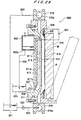
- the plating unit 700 has a plating tank body 702 which houses therein a substrate holder 704 for holding a substrate W.
- the substrate holder 704 has a substrate holding case 706 and a rotatable shaft 708 that is rotatably supported by an inner surface of cylindrical guide member 710 through bearings 712, 712.
- the guide member 710 and the substrate holder 704 are vertically movable with a predetermined stroke by a cylinder 714 provided at the top of the plating tank body 702.
- the substrate holder 704 is allowed to rotate in the direction of arrow A through the rotating shaft 708 by a motor 715 provided at an upper position in the guide member 710.
- the substrate holder 704 has a space C therein which accommodates a substrate presser 720 that comprises a substrate presser plate 716 and a substrate presser shaft 718.
- the substrate presser 720 is vertically movable with a predetermined stroke by a cylinder 722 provided at an upper position within the shaft 708.
- the substrate holding case 706 of the substrate holder 704 has a bottom opening 706a which communicates with the space C.
- the substrate holding case 706 has a step extending around an upper portion of the bottom opening 706a for placing the outer circumferential edge of the substrate W thereon.
- the outer circumferential edge of the substrate W is placed on the step and the upper surface of the substrate W is pressed by the substrate presser plate 716, the outer circumferential edge of the substrate W is sandwiched between the substrate presser plate 716 and the step.
- the lower surface (plating surface) of the substrate W is exposed in the bottom opening 706a.
- a plating chamber 724 is disposed below the substrate holder 704 in the plating tank body 702, i.e., below the plating surface of the substrate W that is exposed in the lower opening 706a.
- a plating liquid Q is ejected from a plurality of plating liquid injection pipes 726 toward the center of the plating chamber 724.
- the plating chamber 724 is surrounded by a collecting gutter 728 for collecting the plating liquid Q that has overflowed the plating chamber 724.
- the plating liquid Q collected in the collecting gutter 728 is returned to a plating liquid storage tank 730.
- the plating liquid Q in the plating liquid storage tank 730 is delivered by a pump 732 horizontally from outwardly of the plating chamber 724 therein.
- the plating liquid Q thus introduced into the plating chamber 724 is turned into a uniform vertical flow toward the plating surface of the substrate W when the substrate W is rotated and contacts with the surface of the substrate.
- the plating liquid Q that has overflowed the plating chamber 724 is collected in the collecting gutter 728, from which the plating liquid Q flows into the plating liquid storage tank 730.
- the plating liquid Q thus circulates between the plating chamber 724 and the plating liquid storage tank 730.
- the level L Q of the plating liquid in the plating chamber 724 is higher than the level L W of the plating surface of the substrate W by a small distance ⁇ L. Therefore, the entire plating surface of the substrate W is contacted with the plating liquid Q.
- the substrate holding case 706 has a substrate takeout opening 706c defined in the sidewall thereof for inserting into and taking out the substrate therethrough by a substrate loading and unloading member such as a robot arm.
- the plating unit 700 operates as follows: The cylinder 714 is operated to lift the substrate holder 704 together with the guide member 710 by a predetermined distance, and the cylinder 722 is operated to lift the substrate presser 720 by a predetermined distance to a position where the substrate presser plate 716 is located above the substrate takeout opening 706c.
- the substrate loading and unloading member such as a robot arm is then actuated to introduce the substrate W through the opening 706c into the space C in the substrate holder 704, and place the substrate W on the step such that the plating surface of the substrate W faces downward.
- the cylinder 722 is operated to lower the substrate presser plate 716 until its lower surface touches the upper surface of the substrate W, thereby sandwiching the outer circumferential edge of the substrate W between the substrate presser plate 716 and the step.
- the cylinder 714 is operated to lower the substrate holder 704 together with the guide member 710 until the plating surface of the substrate W contacts the plating liquid Q (i.e. to the position that is lower than the level L Q of the plating liquid Q by the distance ⁇ L).
- the motor 715 is energized to rotate the substrate holder 704 and the substrate W at a low speed while they are being lowered.
- the plating chamber 724 is filled with the plating liquid Q.
- the motor 715 is continuously energized to rotate the substrate holder 704 and the substrate W at a low speed.
- the speed is selected so as to form a plated film of uniform thickness on the plating surface of the substrate W without disturbing the vertical flow of the plating liquid in the plating chamber 724.
- the cylinder 714 is operated to lift the substrate holder 704 and the substrate W.
- the motor 715 is energized to rotate at a higher speed to drain off the plating liquid from the plated surface of the substrate W and from the lower surface of the substrate holding case 706 by the action of centrifugal force.
- the cylinder 722 is operated to lift the substrate presser plate 716 to release the substrate W, which remains placed on the step of the substrate holding case 706.
- the substrate loading and unloading member such as a robot arm is introduced through the substrate takeout opening 706c into the space C in the substrate holder 704, holds the substrate W, and carries the substrate W through the opening 706c out of the substrate holder 704.
- the above example employs the face-down method of plating with the plating unit 700. However, it is also possible to employ a face-up type plating process, as shown in FIG. 26.
- FIG. 26 shows an example of a plating unit 800 to perform a face-up plating process.
- the plating unit 800 is provided with a substrate holder 802 capable of moving up and down that holds the substrate W with the surface to be plated facing upward and an electrode head 804 positioned above the substrate holder 802.
- the electrode head 804 is in a cup shape with an open bottom and provided with a plating liquid supply inlet 806 at the upper surface which is connected to a plating liquid supply tube (not shown) and an anode 808 disposed at the bottom opening of the electrode head 804 and formed of, for example, a porous material or of a plate having a plurality of through-holes.
- a substantially cylindrical sealing member 810 is provided below the electrode head 804.
- the top of the sealing member 810 surrounds the lower periphery of the electrode head 804, while the diameter of the cylinder decreases toward the bottom.
- a plurality of electrical contact points 812 are disposed outside of the sealing member 810.
- the edge portion of the substrate W contacts the sealing member 810, forming a plating chamber 814 between the sealing member 810 and the substrate W.
- the edge portion of the substrate W contacts the electrical contact points 812 outside the contacting portion with the sealing member 810, making the substrate W function as a cathode.
- the substrate holder 802 holding a substrate W is raised to make the edge portion of the substrate W contact the sealing material 810, thereby forming the plating chamber 814 and allowing the substrate W to function as a cathode.
- a plating liquid is supplied into the electrode head 804 via the supply inlet 806 of the electrode head 804 and introduced through the anode 808 into the plating chamber 814, thereby immersing the anode 808 and the surface of the substrate W, serving as the cathode, in the plating liquid.
- the plating process can be performed on the surface of the substrate W by applying a prescribed voltage from a plating power source between the anode 808 and the substrate W.
- FIG. 27 shows the main portion of the plating section of a plating apparatus according to a sixth embodiment of the present invention.
- the plating section of this plating apparatus includes a plurality of plating units 900 which are capable of opening and closing, and arranged downstream of the cleaning tank 30d shown in FIG. 24, for example, and on two sides.
- a substrate transferring device 904 comprising a robot or the like can move along the central transferring path 902.
- a substrate W is transferred between a substrate holding table 950 housed in the plating unit 900 and the substrate transferring device 904.
- the plating unit 900 performs a plating process on the surface of the substrate W.
- FIG. 28 shows an example of the plating unit 900 shown in FIG. 27.
- the plating unit 900 is provided with a plating tank body 911 and a side plate 912.
- the side plate 912 is disposed facing to the plating tank body 911, and a depression A is formed in the surface of the plating tank body 911 facing the side plate 912.
- a hinge mechanism disposed at the bottom of the side plate 912, the side plate 912 can open and close the depression A formed in the plating tank body 911.
- An insoluble anode plate 913 is disposed on a bottom surface of a bottom member 911a of the plating tank body 911 at the depression A.
- the substrate W is mounted on the surface of the side plate 912 facing the plating tank body 911. With this construction, when the side plate 912 is closed over the depression A of the plating tank body 911, the anode plate 913 and substrate W come to be positioned facing each other at a prescribed distance.
- a neutral porous diaphragm or a cation exchange membrane 914 is mounted on the plating tank body 911 and positioned between the anode plate 913 and the substrate W. The neutral porous diaphragm or cation exchange membrane 914 divides the depression A in the plating tank body 911 into an anode chamber 915 and a cathode chamber 916.
- a top header 918 and a bottom header 919 are provided on the top and bottom of the plating tank body 911, respectively.
- a cavity 918a of the top header 918 and a cavity 919a of the bottom header 919 are in communication with the cathode chamber 916, respectively.
- An inlet 911b communicating with the anode chamber 915 is provided at the bottom thereof, and an overflow outlet 911c communicating with the anode chamber 915 is provided at the top thereof.
- An overflow chamber 920 is provided adjacent to the overflow outlet 911c and at the side of the plating tank body 911.
- a plating liquid held in a plating liquid tank 921 is supplied by a pump 922 to the cavity 919a of the bottom header 919 through a pipe 923, fills the cathode chamber 916, passes the cavity 918a at the top of the plating tank body 911, and returns to the plating liquid tank 921 through a pipe 924.
- An plating liquid held in an anode solution tank 925 is supplied by a pump 926 to the anode chamber 915 through a pipe 927, fills the anode chamber 915, overflows the overflow outlet 911c and flows into the overflow chamber 920. After being stored temporarily in the overflow chamber 920, the plating liquid is returned to the anode solution tank 925 through a discharge outlet 920a and a pipe 928.
- the cathode chamber 916 is hermetically sealed, while the top of the anode chamber 915 is open to the air.
- An annular packing 929 is provided around the outer periphery of the depression A formed in the plating tank body 911.
- the annular packing 929 contacts the peripheral surface of the substrate W to hermetically seal the cathode chamber 916.
- External anode terminals 930 are provided outside of the annular packing 929.
- the side plate 912 closes the depression A, the end of the external anode terminals 930 contact the conducting portion of the substrate W, thereby conducting electricity to the substrate W. Further, the annular packing 929 prevents the external anode terminals 930 from contacting the plating liquid.
- a plating power source 931 is connected between the anode terminals 930 and external anode plate 913.
- the plating liquid is filled into and circulated to the cathode chamber 916, while another plating liquid is filled into and, while being left overflowing, circulated to the anode chamber 915.
- a plated film is formed on the surface of the substrate W by supplying an electric current from the plating power source 931 between the insoluble anode plate 913 and the substrate W, serving as a cathode.
- the anode chamber 915 and the cathode chamber 916 are partitioned, and the plating liquid is separately introduced in the respective chambers.
- the anode chamber 915 and the cathode chamber 916 may be integrated into a single chamber without providing a neutral membrane or a cation exchange membrane.
- a soluble anode plate may also be used as the anode plate 913.
- the substrate holding table 950 in the plating unit 900 may serve also as the side plate 912.
- the substrate holding table 950 which has received the substrate W from the substrate transferring device 904 can move to close the depression A of the plating tank body 911.
- the other construction of the substrate holding table 950 is the same as in the above embodiment.
- the present invention relates to an apparatus and method for plating the processing surface, to be plated, of a substrate.
- the present invention is suited, more particularly, for forming a plated film in fine trenches and plugs for interconnects, and in the openings of a resist formed in the surface of a substrate such as a semiconductor wafer, and for forming bumps (protruding electrodes) on the surface of a semiconductor wafer for electrically connecting semiconductor chips and the substrate.
Landscapes
- Chemical & Material Sciences (AREA)
- Engineering & Computer Science (AREA)
- Chemical Kinetics & Catalysis (AREA)
- Electrochemistry (AREA)
- Materials Engineering (AREA)
- Metallurgy (AREA)
- Organic Chemistry (AREA)
- Automation & Control Theory (AREA)
- Life Sciences & Earth Sciences (AREA)
- Sustainable Development (AREA)
- Electroplating Methods And Accessories (AREA)
- Electrodes Of Semiconductors (AREA)
Abstract
There is provided an apparatus suited for forming a plated
film in fine trenches and plugs for interconnects, and in the
openings of a resist formed in the surface of a substrate such as
a semiconductor wafer, and for forming bumps (protruding
electrodes) on the surface of a semiconductor wafer. The apparatus
includes a substrate holder capable of opening and closing for
holding a substrate such that the front surface of the substrate
is exposed while the backside and the edge thereof are hermetically
sealed; a plating tank accommodating a plating liquid in which an
anode is immersed; a diaphragm provided in the plating tank and
disposed between the anode and the substrate held by the substrate
holder; plating liquid circulating systems for circulating the
plating liquid to the respective regions of the plating tank
separated by the diaphragm; and a deaerating unit disposed in at
least one of the plating liquid circulating systems.
Description
The present invention relates to an apparatus and method for
plating the processing surface, to be plated, of a substrate, and
more particularly to a plating apparatus and method suited for
forming a plated film in fine trenches and plugs for interconnects,
and in the openings of a resist formed in the surface of a substrate
such as a semiconductor wafer, and for forming bumps (protruding
electrodes) on the surface of a semiconductor wafer for
electrically connecting semiconductor chips and the substrate.
FIG. 30 shows the general construction of a conventional
plating apparatus for plating copper or the like on a semiconductor
substrate. As shown in FIG. 30, the conventional substrate plating
apparatus is provided with a plating tank 411 that holds a plating
liquid Q, and arranges a substrate W, such as a semiconductor wafer,
and an anode 412 opposing each other therein. A plating power
source 413 is connected to the substrate W and the anode 412. When
the plating power source 413 applies a prescribed voltage
thereacross, a current containing ions dissolved from the copper
plate or the like serving as the anode 412 flows toward the surface
(processing surface to be plated) of the substrate W and forms a
plated copper film thereon. The substrate W is detachably held
by a substrate holder 414. When the current flows between the anode
412, which is formed of copper containing phosphorus, for example,
and the substrate W, the ionized copper is conveyed by the plating
current and deposited on the surface of the substrate W to form
a plated film. The plating liquid Q overflowing the wall 415 of
the plating tank 411 is collected in a recovery tank 416. The
plating liquid Q in the recovery tank 416 is reintroduced to the
plating tank 411 through a plating liquid circulation system
comprising a pump 420, a temperature regulating tank 421,a filter
422 and a flow meter 423 and so on.
When forming a plated film in fine trenches and plugs for
interconnects, or in openings of a resist having poor wettability
formed in a substrate, such as a semiconductor water, a plating
liquid or a pretreatment liquid cannot enter deep inside of the
trenches, plugs and openings, thereby leaving air bubbles therein.
Such air bubbles can cause plating defects or incomplete plating.
In order to prevent such plating defects or incomplete
plating, it has been conventionally conducted to lower the surface
tension of a plating liquid by adding a surfactant thereto, thereby
facilitating entering of the plating liquid into the fine trenches
and plugs for interconnects of the substrate to be plated, or the
openings of a resist. However, air bubbles tend to generate more
easily in a plating liquid during circulation when the surface
tension of the plating liquid is low. Further, the addition of
a surfactant to the plating liquid can cause an abnormal plating
deposition and increase the amount of an organic substance taken
in the plated film, leading to lowering of the properties of the
plated film.
In a tape automated bonding (TAB) or flip chip, for example,
it has been widely conducted to deposit gold, copper, solder, nickel
or multi-layered materials thereof at prescribed areas
(electrodes) on the surface of a semiconductor chip having
interconnects, thereby forming protruding connecting electrodes
(bumps). Such bumps electrically connect the semiconductor chip
with substrate electrodes or TAB electrodes. There are various
methods for forming these bumps, including electrolytic plating
method, vapor deposition method, printing method, and ball bump
method. The electrolytic plating method has become in wide use
due to its relatively stable performance and capability of forming
fine connections, in view of the recent tendency to increasing
number of I/O terminals on semiconductor chips and to finer pitch.
The electrolytic plating method includes a spurting or cup
method in which a substrate such as a semiconductor wafer is
positioned horizontally with the processing surface to be plated
facedown and a plating liquid is spurted from below; and a dipping
method in which the substrate is placed vertically in a plating
tank and immersed in a plating liquid, while a plating liquid is
supplied from the bottom of the plating tank and is allowed to
overflow the tank. According to the dipping method of electrolytic
plating, bubbles that can adversely affect the quality of the
plating are easily removed and the footprint is small. Further,
the dipping method can be readily adapted to variations in wafer
size. The dipping method is therefore considered to be suited for
bump plating in which holes to be filling by the plating are
relatively large and which requires a fairly long plating time.
When forming bumps at prescribed areas of a substrate having
interconnects, a seed layer 500 as an electric feed layer is first
formed on the surface of the substrate W, as shown in FIG. 29A.
A resist 502 having a height H of e.g. 20-120 µm is applied to the
entire surface of the seed layer 500. An opening 502a having a
diameter D of e.g. 20-200 µm is formed in a prescribed portion of
the resist 502. Plating is performed onto such a surface of the
substrate W to deposit and grow a plated film 504 in the opening
502a, thereby forming a bump 506 (see FIGS. 29B-29E). When using
the facedown-type electrolytic plating to form the bump 506, air
bubbles 508 generated in the plating liquid are likely to remain
in the inside of the opening 502a, as shown by the dotted line in
FIG. 29A, particularly when the resist 502 is hydrophobic.
When using the dipping -type electrolytic plating apparatus
to form the bump, on the other hand, the air bubbles can escape
easily. Conventional electrolytic plating apparatuses for the
dipping method employ a substrate holder which holds a substrate
sealing the edge and the backside thereof, such as a semiconductor
wafer, while exposing the front surface (processing surface to be
plated). Since such a substrate holder is immersed in the plating
liquid with the substrate when plating the surface of the substrate,
it is difficult to automate the entire plating process from loading
of the substrate to unloading of the substrate after plating.
Further, the plating apparatus occupies a considerably large
space.
The present invention has been made in view of the above
drawbacks in the related art. It is therefore a first object of
the present invention to provide a plating apparatus and method
which enables a plating liquid entering into fine trenches and plugs
for wiring and into openings of a resist formed in a substrate,
without adding a surfactant to the plating liquid, and without
suffering from plating defects and incomplete plating.
It is a second object of the present invention to provide
a plating apparatus which employs the dipping method in which air
bubbles can escape relatively easily, and is capable of
automatically forming a plated metal film suitable for protruding
connecting electrodes such as bumps, and which does not occupy a
large space.
A first embodiment of a plating apparatus according to the
present invention comprises: a substrate holder capable of opening
and closing for holding a substrate such that the front surface
of the substrate is exposed while the back side and the edge thereof
are hermetically sealed; a plating tank for holding a plating liquid
in which an anode is immersed; a diaphragm provided in the plating
tank and disposed between the anode and the substrate held by the
substrate holder; plating liquid circulating systems for
circulating the plating liquid through the respective regions of
the plating tank partitioned by the diaphragm; and a deaerating
unit provided in at least one of the plating liquid circulating
systems.
Described above, the diaphragm, such as an ion exchange
membrane or a neutral porous diaphragm, is disposed between the
substrate and the anode, thereby preventing particles generated
on the anode side from flowing through the diaphragm to the
substrate side.
Further, at least one of the plating liquid circulating
systems for circulating a plating liquid through the regions in
the plating tank partitioned by the diaphragm is provided with a
deaerating unit for removing gas from the plating liquid during
the plating process. Accordingly, it is possible to maintain a
low concentration of dissolved gases in the plating liquid, thereby
reducing generation of gas bubbles in the plating liquid that can
cause plating defects.
The plating apparatus preferably further comprises a
monitoring unit disposed downstream of the deaerating unit for
monitoring the concentration of dissolved oxygen in the plating
liquid. With this construction, the plating liquid circulating
system is provided with a unit for measuring and controlling
dissolved gases. Accordingly, it is possible to maintain a uniform
concentration of dissolved gas in the plating liquid so as to
achieve a constant and stable high-quality plating process.
The deaerating unit preferably comprises at least a
deaerating membrane and a vacuum pump, the pressure on the
decompressed side of the deaerating unit being controlled. With
this construction, it is possible to easily remove dissolved gases
from the plating liquid.
A plating method according to the present invention,
comprising: providing a diaphragm between a substrate and an anode
immersed in a plating liquid held in a plating tank; circulating
the plating liquid in each region of the plating tank partitioned
by the diaphragm; and plating the substrate while maintaining the
concentration of dissolved oxygen in the plating liquid between
1 µg/l (1 ppb) and 4 mg/l (4 ppm) by a deaerating unit.
A second embodiment of a plating apparatus according to the
present invention, comprises: a cassette table for loading a
cassette housing a substrate therein; a substrate holder capable
of opening and closing for holding the substrate such that the front
surface of the substrate is exposed while the back side and the
edge thereof are hermetically sealed; a substrate
loading/unloading unit for supporting the substrate holder, and
loading and unloading the substrate; a substrate transferring
device for transferring the substrate between the cassette table
and the substrate loading/unloading unit; a plating tank for
accommodating the substrate holder and the substrate held
vertically and facing to an anode, and plating the surface of the
substrate by injecting a plating liquid from the bottom thereof;
and a substrate holder transferring device having a transporter
that grips the substrate holder and is vertically moveable, and
transfers the substrate holder between the substrate
loading/unloading unit and the plating tank.
By starting the plating apparatus after loading the cassette
housing substrates on the cassette table, it is possible to fully
automate the electrolytic plating process employing the dipping
method. Accordingly, it is possible to automate the formation of
a plated metal film on the surface of a substrate suitable for bump
electrodes and the like.
The plating tank may comprise a plurality of plating units
accommodated in an overflow tank that accommodate electrodes for
dummy plating, each unit being adapted for accommodating and
plating one substrate. With this configuration, the overflow tank
serves as a plating tank, thereby eliminating uneven plating
between the plating units. This configuration also increases the
surface of the electrodes for dummy plating, thereby improving
efficiency of the dummy plating process. Further, since most of
the plating liquid is circulated through the dummy electrolytic
section, it is possible to facilitate formation of a uniform plating
liquid state.
Each plating unit is preferably provided with a paddle that
is disposed between the anode and the substrate, and reciprocates
to agitate the plating liquid. With this construction, the paddle
generates a uniform flow of plating liquid across the entire surface
of the substrate, thereby enabling formation of a plated film having
a uniform thickness over the entire surface of the substrate.
A paddle drive device for driving the paddles is preferably
provided on the opposite side of the substrate holder transferring
device with respect to the plating tank. With this construction,
it is possible to facilitate maintenance of the substrate holder
transferring device and the paddle drive device.
The plating apparatus may comprise plating tanks for
performing different types of plating, wherein each plating tank
comprises an overflow tank and plating units for performing each
type of plating, the plating units being accommodated in the
overflow tank. With this construction, it is possible to form
multi-layer bumps comprising copper-nickel-solder, for example,
in a continuous process.
A local exhaust duct may be provided along one side of the
plating tank. With this construction, an air flow is generated
in a single direction toward the local exhaust duct. Accordingly,
a vapor emitted from the plating tanks can be carried on this air
flow, thereby preventing the vapor from contaminating the
semiconductor wafers and the like.
A stocker for storing the substrate holder in a vertical
position may be provided between the substrate loading/unloading
unit and the plating tank; and the substrate holder transferring
device may have first and second transporters. By performing
transferring operations with separate transporters, the substrate
holder can be transferred more smoothly, thereby increasing
throughput.
The substrate loading/unloading unit may preferably be
provided with a sensor for checking the contact state between the
substrate and contact points when the substrate is loaded into the
substrate holder; and the second transporter selectively transfers
only such substrate that has a good contact with the contact points
to a subsequent process. With this construction, the plating
operation need not be halted but allows to be continuing, if a poor
contact is detected between the substrate and contact points when
the substrate is loaded into the substrate holder. The substrate
in which the poor contact is detected does not apply to the plating
process, but instead is discharged from the cassette after being
returned thereto.
The substrate holder transferring device may employ a linear
motor as a means for moving the transporter. With this
construction, the transporter can be moved over a long distance
and the overall length of the apparatus can be reduced. Further,
parts such as long ball screws that require high-precision and
maintenance can be eliminated.
The plating apparatus may further comprises a pre-wetting
tank, blowing tank, and cleaning tank between the stocker and the
plating tank. With this construction, it is possible to perform
a series of processes in the same apparatus, such as immersing the
substrate in pure water held in the pre-wetting tank to wet the
surface of the substrate and improve its hydrophilic properties,
performing the plating operation, thereafter cleaning the
substrate in pure water in the cleaning tank, and drying the
substrate in the blowing tank. When performing a plating process
using solder, copper or other metals that can be oxidized to form
an oxide film, the substrate should be placed in a pre-soaking tank
after pre-wetting tank, wherein the oxide film on the seed layer
is removed through chemical etching, before performing the plating
operation.
The substrate loading/unloading unit may be constructed to
support two substrate holders side by side that are slidable
laterally. With this construction, the apparatus requires only
one mechanism for opening and closing the substrate holder and
avoids the need to move the substrate transferring device
laterally.
A first embodiment of a plating apparatus for forming a
protruding electrode according to the present invention concerns
an apparatus for forming a protruding electrode on a substrate
having wiring formed thereon, comprising: a cassette table for
loading a cassette housing the substrate therein; a plating tank
for plating the substrate; a cleaning unit for cleaning the plated
substrate; a drying unit for drying the cleaned substrate; a
deaerating unit for deaerating a plating liquid in the plating tank;
a plating liquid regulating unit for analyzing the components of
the plating liquid and adding components to the plating liquid based
on the results of the analysis; and a substrate transferring device
for transferring the substrate.
A second embodiment of a plating apparatus for forming a
protruding electrode according to the present invention concerns
an apparatus for forming a protruding electrode on a substrate
having wiring formed thereron comprising: a cassette table for
loading a cassette housing the substrate therein; a pre-wetting
tank for applying a pre-wetting treatment to the substrate to
increase the wettability thereof; a plating tank for plating the
substrate after the pre-wetting treatment; a cleaning unit for
cleaning the plated substrate; a drying unit for drying the cleaned
substrate; a deaerating unit for deaerating a plating liquid in
the plating tank; and a substrate transferring device for
transferring the substrate.
A third embodiment of a plating apparatus for forming a
protruding electrode according to the present invention concerns
an apparatus for forming a protruding electrode on a substrate
having wiring formed thereon comprising: a cassette table for
loading a cassette housing the substrate therein; a pre-soaking
tank for applying a pre-soaking treatment to the substrate; a
plating tank for plating the substrate after the pre-soaking
treatment; a cleaning unit for cleaning the plated substrate; a
drying unit for drying the cleaned substrates; a deaerating unit
for deaerating the plating liquid in the plating tank; and a
substrate transferring device for transferring the substrates.
A fourth embodiment of a plating apparatus for forming a
protruding electrode according to the present invention concerns
an apparatus for forming a protruding electrode on a substrate by
plating the substrate with at least two kinds of metals, comprising:
a plurality of plating tanks each for plating the substrate with
each of the above metals; and a substrate transferring device for
transferring the substrate, wherein the plating tanks are disposed
along a transferring path of the substrate transferring device.
A fifth embodiment of a plating apparatus for forming a
protruding electrode according to the present invention concerns
an apparatus for forming a protruding electrode on a substrate
having wiring formed thereon, comprising: a cassette table for
loading a substrate cassette thereon; a plating tank for plating
the substrate; a cleaning unit for cleaning the plated substrate;
a drying unit for drying the cleaned substrate; a deaerating unit
for deaerating a plating liquid in the plating tank; an annealing
unit for annealing the plated substrate; and
a substrate transferring device for transferring the substrate.
A first embodiment of a plating method for forming protruding
electrodes according to the present invention concerns a method
for forming a protruding electrode on a substrate having wiring
formed thereon, comprising: holding a substrate taken out of a
cassette by a substrate holder; pre-wetting the substrate held by
the substrate holder; plating the pre-wetted surface of the
substrate by immersing the substrate together with the substrate
holder in a plating liquid; cleaning and drying the plated substrate
together with the substrate holder; and taking the substrate out
of the substrate holder and drying the substrate.
A second embodiment of a plating method for forming a
protruding electrode according to the present invention concerns
a method for forming a protruding electrode on a substrate having
wiring formed thereon, comprising: holding a substrate taken out
of a cassette by a substrate holder; pre-soaking the substrate held
by the substrate holder; plating the pre-soaked surface of the
substrate by immersing the substrate together with the substrate
holder in a plating liquid; cleaning and drying the substrate
together with the substrate holder; and taking the substrate out
of the substrate holder and drying the substrate.
Preferred embodiments of a plating apparatus according to
the present invention will be described with reference to FIGS.
1 through 28. FIG. 1 shows the construction of a plating apparatus
according to a first embodiment of the present invention. As shown
in FIG. 1, the plating apparatus includes a cation exchange membrane
318 as a diaphragm which is disposed between a cathode (substrate
W) and an anode 312 connected to a plating power source 313. The
cation exchange membrane (diaphragm) 318 partitioned the space in
the plating tank 311 into two regions T1 including the substrate
W and T2 including the anode 312. The plating apparatus of this
embodiment is a copper-plating apparatus designed to form a plated
copper film on the surface (processing surface to be plated) of
the substrate W. The anode 312 is a soluble anode and a plating
liquid Q is a copper sulfate solution. The substrate W, which is
detachably held by the substrate holder 314 with a watertight seal
being made over the backside of the substrate W, is immerse in the
plating liquid Q.
The cation exchange membrane 318 only allows passage of Cu
ions dissolved from the soluble anode 312, while blocking passage
of impurities dissolved from the anode 312. This can minimize the
amount of particles in the plating liquid Q in the substrate W side
region T1 partitioned by the cation exchange membrane 318.
This embodiment employs a cation exchange membrane 318
disposed between the substrate W and the anode 312. However, the
same effects can be obtained by using a neutral porous diaphragm
capable of removing small particles in place of the cation exchange
membrane 318.
The cation exchange membrane 318, having the capability of
selectively filtering ions according to their electrical energy,
can be a commercial product. One such example of the cation
exchange membrane 318 is "Selemion" manufactured by Asahi Glass
Co., Ltd. The neutral porous diaphragm is a porous membrane formed
of synthetic resin and having extremely small holes of uniform
diameter. One such example is a product called "YUMICRON"
manufactured by Yuasa Ionics Co., Ltd., which is composed of a
polyester nonwoven fabric as a base material and of polyvinylidene
fluoride and titanium oxide as a membrane material.
A first plating liquid circulation system C1 which circulates
the plating liquid Q, which overflows the wall 315 of the plating
tank 311 and collects in the recovery tank 316, back to the region
T1 on the substrate W side of the plating tank 311 is provided on
the substrate W side of the plating tank 311. The first plating
liquid circulation system C1 includes a vacuum pump 320 that
circulates the plating liquid Q through a temperature regulating
unit 321, a filter 322, a deaerator (deaerating unit) 328, a
dissolved oxygen concentration measuring unit 340, and a flow meter
323. The temperature regulating unit 321 stabilizes the growth
rate of the plated film by maintaining the plating liquid Q at a
prescribed temperature. The filter 322 removes particles from the
plating liquid Q before the plating liquid Q is reintroduced into
the plating tank 311.
The deaerator 328 removes dissolved gases from the plating
liquid Q flowing through the first plating liquid circulation
system C1. The deaerator 328 is provided with a vacuum pump 329
for removing various dissolved gases including oxygen, air, and
carbon dioxide and the like from the plating liquid Q flowing
through the circulation system using a membrane which allows only
gases to pass therethrough, while preventing the passage of liquid.
The vacuum pump 329 removes dissolved gases from the plating liquid
by drawing the gases through the membrane in the deaerator 328.
The dissolved oxygen concentration measuring unit 340 is provided
in the first plating liquid circulation system C1 to monitor the
concentration of dissolved oxygen in the plating liquid
circulating through the first plating liquid circulation system
C1. Based on the results of the measurements, it is possible to
regulate the pressure on the decompressed side of the deaerator
328 using a control unit (not shown) for controlling the rotational
speed of the vacuum pump 329 or the like. With this method, it
is possible to regulate the dissolved gases in the plating liquid
at a desired concentration. It is desirable to maintain the
concentration of dissolved oxygen between approximately 1 µg/l (1
ppb) and 4 mg/l (4 ppm). With this concentration, it is possible
to eliminate bubbles dissolved in the plating liquid nearly into
zero, thereby forming a satisfactory plated film.
The flow meter 323 measures the flow of the plating liquid
Q circulating through the first plating liquid circulation system
C1 and transmits a signal representing this flow to a control unit
(not shown). The control unit maintains the amount of plating
liquid Q circulating through the first plating liquid circulation
system C1 at a fixed prescribed amount by controlling the speed
of the vacuum pump 320, for example, thereby achieving stable
plating in the plating tank 311.
A second plating liquid circulation system C2 is provided
on the anode 312 side of the plating tank 311 partitioned by the
cation exchange membrane 318. The second plating liquid
circulation system C2 circulates the plating liquid Q overflowing
the plating tank 311 back to the region T2 on the anode side of the
plating tank 311 by the pump 320 through the temperature regulating
unit 321, filter 322, and flow meter 323. The flow meter 323
measures the flow of the plating liquid Q circulating through the
second plating liquid circulation system C2 and transmits a signal
representing this flow to a control unit (not shown). The control
unit maintains the amount of plating liquid Q circulating through
the second plating liquid circulation system C2 at a fixed rate
by controlling the speed of the vacuum pump 320 or the like.
FIG. 2 shows a plating apparatus according to a second
embodiment of the present invention. In this embodiment, the
second plating liquid circulation system C2 disposed on the anode
312 side of the plating tank 311 partitioned by the cation exchange
membrane 318 is further provided with the deaerator (deaerating
device) 328 and dissolved oxygen concentration measuring unit 340.
Accordingly, the plating liquid Q is deaerated while being
circulated to both the regions T1 on the substrate W (anode) side
and T2 on the anode 312 side partitioned by the cation exchange
membrane 318. Therefore, it is possible to further reduce the
amount of gas bubbles in the plating liquid compared to the first
embodiment shown in FIG. 1.
While not shown in the drawings, it is also possible to omit
the deaerator 328 in the first plating liquid circulation system
C1 on the substrate W side, and only provide the deaerator 328 in
the second plating liquid circulation system C2 on the anode 312
side partitioned by the cation exchange membrane 318. This
configuration can also supply the plating liquid with an extremely
low amount of dissolved gases to the substrate W, since copper ions
in the plating liquid are carried by the electrical current from
the anode 312 side to the substrate W side.
By providing a deaerator 328 in the first plating liquid
circulation system C1 and/or second plating liquid circulation
system C2, as described above, air bubbles introduced into the
plating liquid when the plating liquid Q overflows the plating tank
311 and collects in the recovery tank 316 are removed when passing
through the deaerator 328. As a result, dissolved oxygen and other
dissolved gases are removed from the plating liquid Q, thereby
preventing a reaction in the plating liquid caused by the dissolved
gases and achieving a stable plating environment capable of
restraining side reactions and degradation of plating liquid.
The embodiments described above show copper plating on the
surface of a semiconductor wafer. However, the object of the
plating is not limited to semiconductor wafers. The present
invention can also be applied to other types of substrates.
Further, plating metal other than copper can be used in the anode.
While the deaerator and dissolved oxygen concentration measuring
unit are disposed in the circulating paths of the plating liquid
in the embodiments described above, these units can also be disposed
in the plating tank itself. In this way, many variations to the
embodiments can be made without departing from the scope of the
invention.
The plating apparatuses of the above embodiments can provide
optimal plating conditions, due to the provision of a deaerator
(deaerating unit) 328 in at least one of the circulation systems
C1 and C2 partitioned by the cation exchange membrane (diaphragm)
318 for deaerating the plating liquid Q prior to the plating process
or during the plating process. By preventing the generation of
air bubbles on the anode and cathode sides, a plated film can be
efficiently formed on the substrate W without defects caused by
air bubbles.
The dissolved oxygen concentration measuring unit 340
provided in 'the circulation systems C1 and C2 for controlling
dissolved gases in the plating liquid can reduce the amount of
dissolved gases in the plating liquid in the plating tank.
Accordingly, there is less chance for air bubbles to be attached
on the surface of the substrate (processing surface to be plated),
thereby achieving a stable plating process.
FIG. 3A shows the overall construction of a plating apparatus
according to a third embodiment of the present invention. As shown
in FIG. 3A, the plating apparatus is provided with two cassette
tables 12 for placing thereon cassettes 10 that house substrates
W, such as semiconductor wafers; an aligner 14 for aligning the
orientation flat or notch, etc. of the substrate W in a prescribed
direction; and a spin dryer 16 for spin drying the substrate at
a high rotation speed after the plating process, all arranged along
the same circle. A substrate loading/unloading unit 20 for placing
the substrate holders 18 thereon, which detachably hold the
substrates, is provided along a tangent line to the circle. A
substrate transferring device 22, such as a transferring robot,
is disposed in the center of these units for transferring substrates
W therebetween.
As shown in FIG. 3B, it is also possible to provide, around
the substrate transferring device 22, a resist peeling unit 600
for peeling the resist 502 (see FIGS. 29A-29E) off from the surface
of the substrate; a seed layer removing unit 602 for removing the
unneeded seed layer 500 (see FIGS. 29A-29E) after the plating
process; a heating unit 604 for heating the plated substrate.
Further, as shown in FIG. 3C, a reflowing unit 606 for causing a
plated film 504 (see FIGS. 29B-29D) to reflow and an annealing unit
608 for annealing the substrate after reflowing may be provided
in place of the heating unit 604.
Disposed in a line that proceeds away from the substrate
loading/unloading unit 20 are in order a stocker 24 for keeping
and temporarily placing the substrate holders 18; a pre-wetting
tank 26 holding pure water in which the substrate W is immersed
to make the surface of the substrate more hydrophilic; a pre-soaking
tank 28 holding a sulfuric acid or hydrochloric acid solution or
the like for etching the surface of the seed layer formed on the
surface of the substrate W in order to remove the oxidized layer
having a high electrical resistance; a first cleaning tank 30a
holding pure water for cleaning the surface of the substrate; a
blowing tank 32 for removing water from the substrate after the
cleaning process; a second cleaning tank 30b; and a copper plating
tank 34. The copper plating tank 34 includes an overflow tank 36
and a plurality of copper plating units 38 accommodated in the
overflow tank 36. Each copper plating unit 38 accommodates one
substrate W and performs a plating process on the substrate W.
Although copper plating is described as an example in this
embodiment, the same description naturally holds for nickel,
solder, or gold plating.
A substrate holder transferring device (substrate
transferring device) 40 is provided along the side of the units
for transferring the substrate holders 18 with substrates W to each
unit. The substrate holder transferring device 40 includes a first
transporter 42 for transferring substrates W between the substrate
loading/unloading unit 20 and stocker 24, and a second transporter
44 for transferring substrates W between the stocker 24, pre-wetting
tank 26, pre-soaking tank 28, cleaning tanks 30a and 30b,
blowing tank 32, and copper plating tank 34.
A plurality of paddle driving units 46 are disposed on the
opposite side of the substrate holder transferring device 40 with
respect to the overflow tank 36. The paddle driving units 46 drive
paddles 202 (see FIGS. 20 and 21) positioned in each of the plating
units 38 and serving as stirring rods for agitating the plating
liquid.
The substrate loading/unloading unit 20 is provided with a
flat shaped loading plate 52 capable of sliding horizontally along
rails 50. The loading plate 52 supports two of substrate holders
18 side by side in a level state. After the substrate W is
transferred between one of the substrate holders 18 and the
substrate transferring device 22, the flat loading plate 52 is slid
in a horizontal direction, and then the substrate W is transferred
between the other substrate holder 18 and the substrate
transferring device 22.
As shown in FIGS. 4 through 6, the substrate holder 18
includes a flat, rectangular shaped fixed supporting member 54,
and a ring-shaped moveable supporting member 58 mounted on the fixed
supporting member 54 and capable of opening and closing over the
fixed supporting member 54 through a hinge 56. A ring-like seal
packing 60, having a rectangular cross-section with an open bottom
with one of the parallel sides longer than the other, is mounted
at the fixed supporting menber54 side of the moveable supporting
member 58 through a packing base 59 made of vinyl chloride, serving
as a reinforcing member and having a good lubrication with a clamp
ring 62. The clamp ring 62 is held on the fixed supporting menber54
via bolts 64 passing through a plurality of long holes 62a formed
along the circumference of the clamp ring 62 so as to be rotatable
and not be removed from the fixed supporting member 54.
When the moveable supporting member 58 is in an open state,
a substrate W is inserted and positioned correctly in the center
of the fixed supporting member 54. The moveable supporting member
58 is closed through the hinge 56. Subsequently, the clamp ring
62 is rotated in the clockwise direction until the protrusions 68
slide under the pawls 66 shaped roughly like a upside-down letter
L, thereby locking the moveable supporting member 58 to the fixed
supporting member 54. By rotating the clamp ring 62 in the
counterclockwise direction, the protrusions 68 slide out from
under the pawls 66 shaped roughly like a upside-down letter L,
thereby unlocking the moveable supporting member 58 from the fixed
supporting member 54.
As shown in FIG. 6, when the moveable supporting member 58
is locked on the fixed supporting member 54, the short leg of the
seal packing 60 on the inner side is in press contact with the
surface of the substrate W, while the longer leg on the outer side
is in press contact with the surface of the fixed supporting member
54, thereby forming a reliable seal.
As shown in FIG. 6, conductors (electrical contact points)
70 connected to an external electrode (not shown) are disposed on
the fixed supporting member 54. The edges of the conductors 70
are exposed on the surface of the fixed supporting member 54 at
outer side of the substrate W. Depressions 71 are formed inside
the moveable supporting member 58 through the seal packing 60 at
a position facing the exposed portion of the conductors 70. Ametal
armature 72 is accommodated in each of the depressions 71. Each
of the metal armature 72 has a rectangular cross-section with an
open bottom. A spring 74 presses each of the metal armatures 72
against the fixed supporting member 54.
With this construction, when the moveable supporting member
58 is in a locked position described above, the pressing forces
of the springs 74 provide electrical contacts between the exposed
portions of the conductors 70 and the outer legs of the metal
armatures 72, and also between the inner legs of the metal armatures
72 and the substrate W at the sealed position by the seal packing
60. In this way, electricity can be supplied to the substrate W
while the substrate W is in a sealed state.
At least one of the contacting surface of the conductor 70
which contacts the metal armature 72, the contacting surface of
the metal armature 72 which contacts the conductor 70, and the
contacting surface of the metal armature 72 which contacts the
substrate W is preferably coated with a metal such as gold or
platinum by plating. Alternatively, the conductor 70 and the metal
armature 72 may be made of stainless steal which has an excellent
corrosion resistance.
The moveable supporting member 58 is opened and closed by
a cylinder (not shown) and the weight of the moveable supporting
member 58 itself. A through-hole 54a is formed in the fixed
supporting member 54. The cylinder is provided at a position
facing the through-hole 54a when the substrate holder 18 is mounted
on the loading plate 52. With this construction, the moveable
supporting member 58 is opened by extending a cylinder rod (not
shown) to push the moveable supporting member 58 upward through
the through-hole 54a. By retracting the cylinder rod, the moveable
supporting member 58 closes by its own weight.
In this embodiment, the moveable supporting member 58 is
locked and unlocked by rotating the clamp ring 62. A
locking/unlocking mechanism is provided on the ceiling side. The
locking/unlocking mechanism has pins disposed at positions
corresponding to the holes 62b of the substrate holder 18 placed
on the loading plate 52 and positioned its center side. In this
state, when the loading plate 52 is raised, the pins enter the holes
62b. The clamp ring 62 is rotated by rotating the pins around the
axial center of the clamp ring 62. Since only one
locking/unlocking mechanism is provided, after locking (or
unlocking) one of the substrate holders 18 placed on the loading
plate 52, the loading plate 52 is slid horizontally in order to
lock (or unlock) another substrate holder 18.
The substrate holder 18 is provided with a sensor for
checking that the substrate W is electrically connected to a contact
points when the substrate W is loaded into the substrate holder
18. Signals from the sensor are input to a controller unit (not
shown).
A pair of hands 76, integrally formed on the end of the fixed
supporting member 54 of the substrate holder 18 and shaped
approximately like the letter T, serve as supports when
transferring the substrate holder 18 and when holding the same in
a suspended state. When the protruding ends of the hands 76 are
caught on the upper wall in the stocker 24, the substrate holder
18 is held in a vertically suspended state. The transporter 42
of the substrate holder transferring device 40 grips the hands 76
of the substrate holder 18 in the suspended state and transfers
the substrate holder 18. The substrate holder 18 is also held in
a vertically suspended state on the surrounding walls of the
pre-wetting tank 26, pre-soaking tank 28, cleaning tanks 30a, 30b,
blowing tank 32, and copper plating tank 34.
FIGS. 7 and 8 show a linear motor unit 80 serving as the
transport section of the substrate holder transferring device 40.
The linear motor unit 80 mainly comprises a lengthy base 82 and
two sliders 84, 86 that are capable of sliding along the base 82.
The transporters 42 and 44 are mounted on top of the sliders 84
and 86, respectively. A cable conveyer bracket 88 and a cable
conveyer receiver 90 are provided on the side of the base 82. A
cable conveyer 92 extends along the cable conveyer bracket 88 and
cable conveyer receiver 90.
By employing a linear motor for moving the transporters 42,
44, these transporters 42, 44 can be moved over a long distance
and the overall length of the apparatus can be shortened by
shortening the length of the transporters 42, 44. Further, devices
that require high-precision and maintenance, such as long ball
screws, can be eliminated.
FIGS. 9 through 12 show the transporter 42. A description
of the transporter 44 will be omitted here as the construction is
essentially the same as that of the transporter 42. The
transporter 42 mainly comprises a transporter body 100, an arm 102
protruding horizontally from the transporter body 100, an arm
raising/lowering mechanism 104 for raising and lowering the arm
102, an arm rotating mechanism 106 for rotating the arm 102, and
gripping mechanisms 108 provided in the arm 102 for gripping and
releasing the hands 76 of the substrate holder 18.
As shown in FIGS. 9 and 10, the raising/lowering mechanism
104 includes a rotatable ball screw 110 extending vertically and
a nut 112 that engages with the ball screw 110; a linear motor base
114 is connected to the nut 112. A timing belt 122 is looped around
the drive pulley 118 fixed to the drive shaft of the
raising/lowering motor 116 mounted on the transporter body 100 and
a follow pulley 120 fixed to the top end of the ball screw 110.
With this construction, the raising/lowering motor 116 drives the
ball screw 110 to rotate. The rotation of the ball screw 110 raise
and lower the linear motor base 114 connected to the nut 112,
engaging with the ball screw 110, along a linear motor guide.
As shown in FIG. 10 by the phantom line, the arm rotating
mechanism 106 includes a sleeve 134 that rotatably accommodates
a rotating shaft 130 and fixed to the linear motor base 114 via
a mounting base 132, and a rotating motor 138 fixed to the end of
the sleeve 134 via a motor base 136. A timing belt 144 looped around
a drive pulley 140 fixed to the drive shaft of the rotating motor
138 and a follow pulley 142 fixed to the end of the rotating shaft
130. With this construction, the rotating motor 138 drives the
rotating shaft 130 to rotate. The arm 102 is linked to the rotating
shaft 130 through a coupling 146 and therefore raises and lowers
and rotates together with the rotating shaft 130.
As shown in FIGS. 11 and 12 and indicated by the phantom line
in FIG. 10, the arm 102 includes a pair of side plates 150 that
are coupled with the rotating shaft 130 and rotate together with
the same. The gripping mechanisms 108 are disposed between the
side plates 150, 150. Two gripping mechanisms 108 are provided
in this example. However, only a description of one will be given,
as both have the same construction.
The gripping mechanism 108 includes a fixed holder 152, the
end of which is accommodated between the side plates 150, 150 and
is capable of moving freely in the widthwise direction; guide shafts
154 penetrating through the inner portion of the fixed holder 152;
and a moveable holder 156 connected to one end (the bottom end in
FIG. 12) of the guide shafts 154. A cylinder 158 for movement in
the widthwise direction is mounted on one of the side plates 150.
The fixed holder 152 is coupled to the cylinder 158 through a
cylinder joint 160. A shaft holder 162 is mounted on the other
end (the upper end in FIG. 12) of the guide shafts 154. The shaft
holder 162 is coupled to a cylinder 166 for vertical movement
through a cylinder connector 164.
With this construction, the fixed holder 152 together with
the moveable holder 156 moves in the widthwise direction between
the side plates 150, 150 with the operations of the cylinder 158.
Further, the moveable holder 156 moves up and down, while being
guided by the guide shafts 154 with the operations of the cylinder
166.
When the gripping mechanism 108 grips the hands 76 of the
substrate holder 18 that is suspended in the stocker 24 and the
like, the moveable holder 156 can be lowered to below of the hands
76 while avoiding interference with the hands 76. Subsequently,
the cylinder 158 is operated to position the fixed holder 152 and
moveable holder 156 above and below the hands 76, thereby
interposing the hands 76 between the fixed holder 152 and moveable
holder 156. In this state, the cylinder 166 is operated to grip
the hands 76 between the fixed holder 152 and moveable holder 156.
The grip is released by performing this operation in reverse.
As shown in FIG. 4, a depression 76a is formed on one of the
hands 76 of the substrate holder 18. A protrusion 168 for engaging
the depression 76a is provided on the moveable holder 156 at a
position corresponding to the depression 76a, enabling a more
reliable grip.
FIGS. 13 through 16 shows a copper plating tank 34
accommodating four copper plating units 38 in two rows. The copper
plating tank 34 accommodating eight plating units 38 in two rows,
shown in FIG. 3A, has essentially the same construction. The
construction of the copper plating tank 34 is the same when
increasing the number of copper plating units.
The copper plating tank 34 is provided with an overflow tank
36 formed in a rectangular box shape with an open top. The overflow
tank 36 includes the tops of peripheral walls 170 that protrude
higher than the tops 180 of peripheral walls 172 on each of the
plating units 38 accommodated in the overflow tank 36. A plating
liquid channel 174 is formed around the plating units 38 when the
plating units 38 are accommodated in the overflow tank 36. A pump
inlet port 178 is provided in the channel 174. With this
construction, a plating liquid that overflows the plating units
38 flows into the channel 174 and is discharged through the pump
inlet port 178. Further, the overflow tank 36 is provided with
a liquid leveler (not shown) for maintaining the plating liquid
in each of the plating units 38 at a uniform level.
As shown in FIGS. 13 and 15A, insertion grooves 182 are
provided on the inner side surfaces of the plating units 38 for
guiding the substrate holder 18.
As described above, a plating liquid circulation system C3
is provided for circulating the plating liquid Q which overflows
the plating units 38 and collects in the overflow tank 36 with the
vacuum pump 320. The vacuum pump 320 circulates the plating liquid
Q through a temperature regulating unit 321, a filter 322, a
deaerator (deaerating unit) 328, a dissolved oxygen concentration
measuring unit 340, and a flow meter 323 back to inside of the copper
plating units 38. The deaerator 328 is provided with a vacuum pump
329 for removing various dissolved gases, including oxygen, air,
and carbon dioxide, from the plating liquid Q flowing through the
circulation system using a membrane. The membrane allows only
gases to pass therethrough, while preventing the passage of liquid.
A plating liquid regulating unit 610 is further provided in
a branch off the plating liquid circulation system C3 for analyzing
the plating liquid while one-tenth of the overall plating liquid,
for example, is extracting. Based on the analysis results,
components that are lacking in the plating liquid are added to the
plating liquid. The plating liquid regulating unit 610 includes
a plating liquid regulating tank 612 in which components lacking
in the solution are added. A temperature controller 614 and a
plating liquid analyzing unit 616 for extracting and analyzing a
sample of plating liquid are disposed adjacent to the plating liquid
regulating tank 612. The plating liquid returns from the plating
liquid regulating tank 612 to the plating liquid circulation system
C3 through a filter 620 by the operation of a pump 618.
In this example, the plating apparatus of the present
invention employs both a feedforward control method for predicting
disturbances based on the processing time and the number of
substrates plated and adding components to be needed, and a feedback
control method for analyzing the plating liquid and adding
components that are lacking in the plating liquid based on the
results on that analysis. Of course, it is also possible to use
only the feedback control method.
As shown in FIG. 3D, the plating liquid regulating unit 610
is disposed in a housing 609, for example, that accommodates the
cassette tables 12, substrate loading/unloading unit 20, stocker
24, pre-wetting tank 26, pre-soaking tank 28, cleaning tanks 30a,
30b, and copper plating tank 34. The plating liquid regulating
unit 610 can also be positioned outside the housing 609, as shown
in FIG. 3E.
As shown in FIG. 15B, the pre-wetting tank 26 is provided
with a pure water circulation system C4 which collects the pure
water that has overflowed the pre-wetting unit 26a in the overflow
tank 26b, and returns the pure water to inside the pre-wetting unit
26a through a temperature regulating unit 321, a filter 322, a
deaerator (deaerating unit) 328, and a flow meter 323 by a vacuum
pump 320. The deaerator 328 is provided with a vacuum pump 329
for removing various dissolved gases, including oxygen, air, and
carbon dioxide, from the pure water flowing through the circulation
system using a membrane. The membrane allows only gases to pass
therethrough, while preventing the passage of liquid. A pure water
tank 330 for supplying the pure water to the pure water circulation
system C4 is provided.
As shown in FIG. 16, a plating cathode 184 and an anode 186
for dummy plating are disposed in the plating liquid channel 174.
The anode 186 can be formed of a titanium basket, for example, in
which copper chips or the like are inserted. In this way, the
overflow tank 36 can serve as a plating tank, thereby not only
eliminating uneven plating in the plating units 38, but also
increasing the surface of the dummy electrode for improving the
efficiency of dummy plating. Further, by circulating most of the
plating liquid through the dummy plating section, it is possible
to facilitate formation of a uniform plating liquid.
FIG. 17 shows a cross-sectional view of the copper plating
unit 38. As shown in FIG. 17, an anode 200 is disposed in the
plating unit 38 at a position facing the surface of the substrate
W when the substrate holder 18 holding the substrate W is disposed
along the insertion grooves 182 (see FIGS. 13 and 15). The paddle
202 is positioned substantially vertical between the anode 200 and
substrate W. The paddle 202 can reciprocate in a direction
parallel to the substrate W by the paddle driving unit 46, which
will be described in more detail below.
By providing the paddle 202 between the substrate W and the
anode 200, and reciprocating the paddle 202 in a direction parallel
to the surface of the substrate W, a uniform flow of plating liquid
can be created across the entire surface of the substrate W, thereby
forming a plated film with a uniform thickness over the entire
surface of the substrate W.
In this example, a regulation plate 204 (mask) formed with
a center hole 204a that corresponds to the size of the substrate
W is provided between the substrate W and the anode 200. The
regulation plate 204 lowers an electrical potential around the
periphery of the substrate W, thereby achieving an even more uniform
thickness of the plated film.
FIG. 18 shows a cross-section of the portion of the plating
apparatus in which the copper plating tank 34 is disposed. FIG.
19 shows a more detailed view of the plating liquid injecting
portion of FIG. 18. As shown in FIG. 18, the plating liquid is
supplied to the plating units 38 through plating liquid supply pipes
206 disposed lower the plating units 38. The plating liquid that
overflows the overflow tank 36 is discharged through a plating
liquid discharge pipe 208 disposed at the lower part.
As shown in FIG. 19, the plating liquid supply pipes 206 are
opened inside the plating units 38 at the bottom of them. A
regulating plate 210 is mounted at the open end of the plating liquid
supply pipe 206. The plating liquid is injected through the
regulating plate 210 into the plating unit 38. A waste solution
pipe 212 is attached at one open end to the plating unit 38 and
positioned around the plating liquid supply pipe 206, while the
other end of the waste solution pipe 212 is connected to the plating
liquid discharge pipe 208 through an elbow pipe 214. With this
configuration, the plating liquid near the plating liquid supply
pipe 206 is discharged through the waste solution pipe 212 and
plating liquid discharge pipe 208, and prevented the plating liquid
from being stagnant at this point.
FIGS. 20 and 21 show the paddle driving units 46. In this
example, a plurality of paddle driving units 46 are provided.
Although FIGS. 20 and 21 show only two paddle driving units 46,
each of the paddle driving units 46 has the same construction.
Therefore, duplicate descriptions of this part will be omitted by
designating the same reference number.
The paddle driving unit 46 is provided with a paddle drive
motor 220, a crank 222 coupled to a drive shaft of the paddle drive
motor 220, a cam follower 224 mounted on the far end of the crank
222, and a slider 228 having a grooved cam 226 in which the cam
follower 224 slides. A paddle shaft 230 is coupled to the slider
228 and disposed across the copper plating tank 34. The paddle
202 is vertically attached at prescribed locations along the length
of the paddle shaft 230. A shaft guide 232 supports the paddle
shaft 230 and only allows the paddle shaft 230 to reciprocate in
the lengthwise direction.
With this construction, the drive of the paddle drive motor
220 rotates the crank 222. The rotating movement of the crank 222
is converted into linear movement in the paddle shaft 230 by the
slider 228 and the cam follower 224. As described above, the paddle
202 attached vertically to the paddle shaft 230 reciprocates in
a direction parallel to the substrate W.
Different diameters of substrates W can be easily handled
by adjusting the mounting position of the paddle 202 on the paddle
shaft 230 to a desirable position. Since the paddle 202
reciprocates constantly during the plating process, this movement
has generated wear in the mechanical parts and has caused the
generation of particles through the mechanical sliding. In this
example, however, the construction of the paddle support units has
been improved, thereby improving the durability of the mechanism
and greatly reducing the occurrence of such problems.
Next, a plating process will be described for plating a
series of bump electrodes using the plating apparatus of the
embodiments described above. As shown in FIG. 29A, a seed layer
500 as an electric feed layer is formed on the surface of a substrate.
A resist 502 having a height H of e.g. 20-120 µm is applied over
the entire surface of the seed layer 500. Subsequently, an opening
502a having a diameter D of e.g. 20-200 µm is formed at a prescribed
position in the resist 502. Such a substrate W is inserted in the
cassette 10 described above with the surface (processing surface
to be plated) facing upward. The cassette 10 is loaded onto the
cassette table 12.
The substrate transferring device 22 takes out one substrate
from the cassette 10 on the cassette table 12 and places the
substrate on the aligner 14. The aligner 14 aligns the orientation
flat or notch or the like in the prescribed orientation. Next,
the substrate transferring device 22 transfers the aligned
substrate W to the substrate loading/unloading unit 20.
In the substrate loading/unloading unit 20, two substrate
holders 18 accommodated in the stocker 24 are gripped by the
gripping mechanisms 108 of the transporter 42 of the substrate
holder transferring device 40 simultaneously. After the arm
raising/lowering mechanism 104 raises the arm 102, the arm 102 is
moved to the substrate loading/unloading unit 20. The arm rotating
mechanism 106 rotates the arm 102 at 90° to hold the substrate
holders 18 in a horizontal state. Subsequently, the arm
raising/lowering mechanism 104 lowers the arm 102, placing both
substrate holders 18 on the loading plate 52 simultaneously. The
cylinders are operated to open the moveable supporting members 58
of the substrate holders 18.
While the moveable supporting members 58 are open, the
substrate transferring device 22 inserts the substrate into one
of the substrate holders 18 positioned in the center of the
substrate loading/unloading unit 20. The cylinder performs a
reverse operation to close the moveable supporting member 58.
Subsequently, the moveable supporting member 58 is locked by the
locking/unlocking mechanism. After one substrate W is loaded into
one substrate holder 18, the loading plate 52 is slid horizontally
to load another substrate in the other substrate holder 18.
Subsequently, the loading plate 52 is returned to its original
position.
Thus, each of the surfaces of the substrates to be plated
is exposed in the opening portion of the substrate holder 18. The
seal packing 60 seals the peripheral portion of the substrates W
to prevent the plating liquid from entering thereinto.
Electricity is continued through the plurality of contact points
in areas not in contact with the plating liquid. Wiring is
connected from the contact points to the hands 76 of the substrate
holder 18. By connecting a power source to the hands 76,
electricity can be supplied to the seed layer 500 formed on the
substrate.
Next, the gripping mechanisms 108 of the transporter 42 of
the substrate holder transferring device 40 grip both of the
substrate holders 18 holding the substrate simultaneously, and the
arm raising/lowering mechanism 104 raises the arm 102. After
transferring the substrate holders 18 to the stocker 24, the arm
rotating mechanism 106 rotates the arm 102 by 90° , such that the
substrate holders 18 are positioned vertically. The arm
raising/lowering mechanism 104 lowers the arm 102, thereby
suspending (temporarily placement) the two substrate holders 18
in the stocker 24.
The above process performed by the substrate transferring
device 22, the substrate loading/unloading unit 20, and the
transporter 42 of the substrate holder transferring device 40 is
repeated in order to load substrate W one after another into the
substrate holder 18 accommodated in the stocker 24 and suspend
(temporarily placement) the substrate holder 18 one after another
at prescribed positions in the stocker 24.
When the sensor mounted on the substrate holder 18 for
checking the contact state between the substrate and the contact
points determines a poor contact, the sensor inputs the signal into
a controller (not shown).
Meanwhile, the gripping mechanisms 108 of the other
transporter 44 of the substrate transferring device 40
simultaneously grip two substrate holders 18 that have been holding
the substrates and temporarily placed in the stocker 24. The arm
raising/lowering mechanism 104 of the transporter 44 raises the
arm 102 and the transporter 44.transfers the substrate holders 18
to the pre-wetting tank 26. The arm raising/lowering mechanism
104 lowers the arm 102, thereby immersing the both substrate holders
18 into pure water, for example, held in the pre-wetting tank 26.
The pure water wets the surfaces of the substrates W to create a
more hydrophilic surface. Obviously, an aqueous liquid other than
pure water can be used, providing the liquid can improve the
hydrophilic property of the substrate by wetting the surface of
the substrate and replacing the bubbles in the holes with water.
However, if the sensor mounted on the substrate holder 18
for checking the contact state between the substrate and contact
points has detected a poor contact state, the substrate holder 18
holding the substrate having the poor contact is left stored in
the stocker 24. Accordingly, when a poor contact between a
substrate and the contact points of the substrate holder 18 occurs,
it does not halt the apparatus, but allows plating operations to
continue. The substrate with a poor contact does not apply to the
plating process. Instead the substrate is returned to the cassette
and discharged from the cassette.
Next, the substrate holders 18 holding the substrates are
transferred in the same way as described above to the pre-soaking
tank 28 and the substrates are immersed into a chemical liquid such
as sulfuric acid or hydrochloric acid held in the pre-soaking tank
28. The chemical liquid etches an oxide layer having a high
electrical resistance that is formed on the surface of the seed
layer and exposes a clean metal surface. Next, the substrate
holders 18 holding the substrates are transferred in the same way
to the cleaning tank 30a, wherein the surfaces of the substrates
are cleaned by pure water held therein.
After the cleaning process, the substrate holders 18 holding
the substrates are transferred in the same way as described above
to the copper plating tank 34, which is filled with a plating liquid,
and suspended in the plating units 38. The transporter 44 of the
substrate holder transferring device 40 repeatedly performs this
operation of transferring the substrate holder 18 to the plating
unit 38 and suspending the substrate holder 18 at a prescribed
position therein.
When the all substrate holders 18 are suspended in the
plating units 38, plating liquid is supplied through the plating
liquid supply pipes 206. While the plating liquid overflows into
the overflow tank 36, plating voltages are applied between the
anodes 200 and the substrates. At the same time, the paddle driving
units 46 reciprocate the paddles 202 in a direction parallel to
the surfaces of the substrates, thereby plating the surfaces of
the substrates. At this time, each of the substrate holders 18
is fixed in a suspended state by the hands 76 at the top of the
plating unit 38. Electricity is supplied from a plating power
source to the seed layer on the substrate via the hand fixed portion,
the hand, and the contact points.
The plating liquid is injected into the plating units 38
through the bottom thereof and overflows into the top of the walls
around the plating units 38. The overflowed plating liquid is
regulated of its concentration, and removed of foreign body by the
filter before being reintroduced into the plating units 38 from
the lower portion of the plating units 38. With this circulation
process, the concentration of the plating liquid is maintained at
a constant level. The plating liquid can be maintained at an even
more uniform state by applying a dummy electrolytic voltage between
the cathode 184 and the anode 186 for dummy plating.
After completion of the plating process, the application of
plating voltages, supply of plating liquid, and reciprocation of
the paddles are all stopped. The gripping mechanisms 108 of the
transporter 44 of the substrate holder transferring device 40 grip
two of the substrate holders 18 holding the substrates
simultaneously, and transfer the substrate holders 18 to the
cleaning tank 30b, as described above. The substrate holders 18
are immersed in pure water held in the cleaning tank 30b to clean
the surfaces of the substrates W. Subsequently, the substrate
holders 18 are transferred as described above to the blowing tank
32, where air is blown onto the substrate holders 18 holding the
substrates to remove water droplets deposited thereon. Next, the
substrate holders 18 are returned and suspended at prescribed
positions in the stocker 24, as described above.
The above operation of the transporter 44 of the substrate
holder transferring device 40 is repeatedly conducted. After each
substrate W has applied to the complete plating process, the
substrate holders 18 are returned to the prescribed suspended
position in the stocker 24.
Meanwhile, the gripping mechanisms 108 of the transporter
42 of the substrate holder transferring device 40 simultaneously
grip two of the substrate holders 18 holding the substrates that
have been returned to the stocker 24 after the plating process,
and place the substrate holders 18 on the loading plate 52 of the
substrate loading/unloading unit 20, as described above. At this
time, a substrate for which a poor connection was detected by the
sensor mounted on the substrate holders 18 for checking contact
state between the substrate and contact points and which was left
in the stocker 24 is also transferred to the loading plate 52.
Next, the moveable supporting member 58 in the substrate
holder 18 positioned at the center of the substrate
loading/unloading unit 20 is unlocked by the locking/unlocking
mechanism. The cylinder is operated to open the moveable
supporting member 58. In this state, the substrate transferring
device 22 takes the plating processed substrate out of the substrate
holder 18 and transfers the substrate to the spin dryer 16. The
spin dryer 16 spins the substrate at a high rotation speed for spin
drying (draining). The substrate transferring device 22 then
transfers the substrate back to the cassette 10.
After the substrate is returned to the cassette 10, or during
this process, the loading plate 52 is slid laterally, and the same
process is performed for the substrate mounted in the other
substrate holder 18 so that the substrate is spin-dried and returned
to the cassette 10.
The loading plate 52 is returned to its original position.
Next, the gripping mechanisms 108 of the transporter 42 grip two
substrate holders 18 which now contain no substrate, at the same
time, and return the substrate holders 18 to the prescribed position
in the stocker 24, as described above. Subsequently, the gripping
mechanisms 108 of the transporter 42 of the substrate holder
transferring device 40 grip two of the substrate holders 18 holding
the substrates that have been returned to the stocker 24 after the
plating process, and transfers the substrate holders 18 onto the
loading plate 52, as described above. The same process is
repeated.
The process is completed when all substrates have been taken
out of the substrate holders, which have been holding substrates
after the plating process and returned to the stocker 24, spin-dried
and returned to the cassette 10. This process provides substrates
W that have a plated film 504 grown in the opening 502a formed in
the resist 502, as shown in FIG. 29B.
In a plating apparatus having a resist peeling unit 600, seed
layer removing unit 602, and heating unit 604, as shown in FIG.
3B, the substrate W is spin dried, as described above, and
transferred to the resist peeling unit 600. Here, the substrate
W is immersed in a solvent, such as acetone, that is maintained
at a temperature of 50-60°C, for example. In this process, the
resist 502 is peeled off from the surface of the substrate W, as
shown in FIG. 29C. Next, the substrate W is transferred to the
seed layer removing unit 602 where the unnecessary seed layer 500
exposed after the plating process is removed, as shown in FIG. 29D.
Next, the substrate W is transferred to the heating unit 604
comprising e.g. a diffusion furnace, and the plated film 504 is
caused to reflow for thereby forming the bump 506 having a spherical
shape due to surface tension as shown in FIG. 29E. Further, the
substrate W is annealed at a temperature of, for example, 100°C
or higher, thereby removing residual stress in the bump 506. This
annealing process helps to form an alloy in the bump 506 when forming
a bump by multi-layer plating, as described below. After the
annealing process, the substrate W is returned to the cassette 10
to complete the process.
Further, as shown in FIG. 3C, in the plating apparatus having
a reflowing unit 606 and an annealing unit 608 in place of the
heating unit 604, the plated film 504 is caused to reflow in the
reflowing unit 606, and then the substrate is transferred to the
annealing unit 608 and annealed therein.
In this example, the stocker 24 for accommodating the
substrate holders 18 in a vertical position is provided between
the substrate loading/unloading unit 20 and plating units 38. The
first transporter 42 of the substrate holder transferring device
40 transfers the substrate holders 18 between the substrate
loading/unloading unit 20 and stocker 24, and the second
transporter 44 of the substrate holder transferring device 40
transfers the substrate holders 18 between the stocker 24 and
plating units 38, respectively. Unused substrate holders 18 are
stored in the stocker 24. This is designed to improve throughput
by providing smooth transferring of the substrate holders 18 on
either side of the stocker 24. However, it is of course possible
to use one transporter to perform all transferring operations.
Further, a robot having a dry hand and a wet hand may be
employed as the substrate transferring device 22. The wet hand
is used only when taking out plating-processed substrates from the
substrate holders 18. The dry hand is used for all other operations.
In principle, the wet hand is not necessarily required since the
backside of the substrate does not contact with plating liquid due
to the seal of the substrate holder 18. However, by using the two
hands in this manner, it is possible to prevent a possible
contamination with a plating liquid due to poor sealing or
transferring to the backside of a rinse water, etc. from
contaminating the backside of a new substrate.
Further, a bar code may be attached to the cassette 10. By
inputting information such as the usage state of the substrate
holder 18 such as storage position of the substrate holder 18 in
the stocker 24, the relationship between the cassette 10 and the
substrate W housed in the cassette 10, or the relationship between
the substrate holder 18 and the substrate W taken out of the
substrate holder 18 from a control panel or the like, the substrate
taken out of the cassette 10 before a plating process can be returned
to the same cassette 10 after the plating process, and the
processing state of the substrate W and the state of the substrate
holder 18 can be monitored. Alternatively, by attaching a bar code
to the substrate, the substrate itself may be managed.
FIGS. 22A and 23 show a plating apparatus according to a
fourth embodiment of the present invention. This apparatus is
provided with plating tanks for performing different types of
plating processes and adapted to various processes freely.
FIG. 22A shows a plating section provided with plating tanks
for performing various types of plating processes. The plating
section includes the stocker 24; a temporary storing platform 240;
the pre-wetting tank 26; the pre-soaking tank 28; the first cleaning
tank 30a; a nickel plating tank 244 having an overflow tank 36a
and a plurality of nickel plating units 242 disposed in the overflow
tank 36a for performing nickel plating on the surface of a
substrate; the second cleaning tank 30b; the copper plating tank
34 having the overflow tank 36 and a plurality of the copper plating
units 38 disposed in the overflow tank 36 for performing copper
plating on the surface of a substrate; the third cleaning tank 30c;
the blowing tank 32; the fourth cleaning tank 30d; and a solder
plating tank 248 having an overflow tank 36b and a plurality of
solder plating units 246 disposed in the overflow tank 36b for
performing solder plating on the surface of a substrate.
The constructions of the nickel plating units 242 and the
solder plating units 246 are essentially the same as that of the
copper plating units 38. Further, the constructions of the nickel
plating tank 244 and solder plating tank 248 accommodating the
respective units in the respective overflow tanks have essentially
the same construction as the copper plating tank 34. All other
constructions are the same as these described in the first
embodiment.
In this embodiment, the substrate mounted in the substrate
holder 18 applied to nickel plating, copper plating, and solder
plating in order on its surface. Thus, this apparatus can perform
a series of operations to form bump electrodes and the like with
multiple plating: nickel, copper, and solder.
In this example, the plating apparatus includes four nickel
plating units 242, four copper plating units 38, and fourteen solder
plating units 246 (22 plating units in total). However, as shown
in FIG. 22B, for example, the apparatus can comprise four nickel
plating units 242, four copper plating units 38, and eighteen solder
plating units 246 (26 plating units in total). Of course, the
number of each type of plating units can be set arbitrarily. Also,
the kind of metal to be plated in each unit can also be varied.
In addition to the Ni-Cu-solder multi-layer bumps, other
types of multi-layer bumps that can be formed include Cu-Au-solder,
Cu-Ni-solder, Cu-Ni-Au, Cu-Sn, Cu-Pd, Cu-Ni-Pd-Au, Cu-Ni-Pd,
Ni-solder, and Ni-Au etc. The type of solder used here can be
either a high melting point solder or a eutectic solder.
Further, bumps composed of multi-layers of Sn-Ag or Sn-Ag-Cu
can be formed as alloys by performing the annealing process
described above. Unlike the conventional Sn-Pb solder, Pb-free
solder resolves the environmental problem of generating alpha
rays.
In this embodiment, a local exhaust duct 250 is disposed
alongside the substrate holder transferring device 40 and parallel
therewith, as shown in FIG. 23, and a plurality of duct holes 252
are formed in communication with the local exhaust duct 250. The
duct holes 252 are designed to suck air toward the local exhaust
duct 250 to generate an air flow in a single direction from the
bottom of each plating tank toward the ceiling. With this
configuration, a vapor emitted from each plating tank is carried
by this air flow in a single direction toward the local exhaust
duct 250, thereby preventing the vapor from contaminating the
substrate, etc.
According to the plating apparatus in this embodiment, by
loading cassettes housing substrates onto the cassette table and
starting the apparatus, it is possible to completely automate the
electrolytic plating process by the dipping method to
automatically form an appropriate plated metal layer for bump
electrodes and the like on the surfaces of the substrates.
In this embodiments described above, the substrate holder
holds the substrate while sealing the peripheral edges and backside
thereof. The substrate and substrate holder are transferred
together to apply to each process. However, the substrates can
also be accommodated in a rack-like transferring device for
transferring the substrates. In this case, a thermally oxidized
layer (Si oxide layer), an adhesive tape film, or the like can be
applied to the backside of the substrates to prevent the same from
being plated.
Further according to the embodiments described above, the
automatic electrolytic plating process using the dipping method
is performed to form bumps on the substrate. However, such bumps
can also be formed by a fully automated electrolytic plating process
of a jet type or cup type in which a plating liquid is spurted from
below.
FIG. 24 shows the main portion of the plating section of a
plating apparatus according to a fifth embodiment. Here, a plating
section including a plurality of jet or cup type plating units 700
are arranged downstream of the cleaning tank 30d shown in FIG. 22A,
for example. The plating units 700 perform a plating process such
as copper plating.
FIG. 25 shows the plating unit 700 shown in FIG. 24. The
plating unit 700 has a plating tank body 702 which houses therein
a substrate holder 704 for holding a substrate W. The substrate
holder 704 has a substrate holding case 706 and a rotatable shaft
708 that is rotatably supported by an inner surface of cylindrical
guide member 710 through bearings 712, 712. The guide member 710
and the substrate holder 704 are vertically movable with a
predetermined stroke by a cylinder 714 provided at the top of the
plating tank body 702.
The substrate holder 704 is allowed to rotate in the
direction of arrow A through the rotating shaft 708 by a motor 715
provided at an upper position in the guide member 710. The
substrate holder 704 has a space C therein which accommodates a
substrate presser 720 that comprises a substrate presser plate 716
and a substrate presser shaft 718. The substrate presser 720 is
vertically movable with a predetermined stroke by a cylinder 722
provided at an upper position within the shaft 708.
The substrate holding case 706 of the substrate holder 704
has a bottom opening 706a which communicates with the space C. The
substrate holding case 706 has a step extending around an upper
portion of the bottom opening 706a for placing the outer
circumferential edge of the substrate W thereon. When the outer
circumferential edge of the substrate W is placed on the step and
the upper surface of the substrate W is pressed by the substrate
presser plate 716, the outer circumferential edge of the substrate
W is sandwiched between the substrate presser plate 716 and the
step. The lower surface (plating surface) of the substrate W is
exposed in the bottom opening 706a.
A plating chamber 724 is disposed below the substrate holder
704 in the plating tank body 702, i.e., below the plating surface
of the substrate W that is exposed in the lower opening 706a. A
plating liquid Q is ejected from a plurality of plating liquid
injection pipes 726 toward the center of the plating chamber 724.
The plating chamber 724 is surrounded by a collecting gutter 728
for collecting the plating liquid Q that has overflowed the plating
chamber 724.
The plating liquid Q collected in the collecting gutter 728
is returned to a plating liquid storage tank 730. The plating
liquid Q in the plating liquid storage tank 730 is delivered by
a pump 732 horizontally from outwardly of the plating chamber 724
therein. The plating liquid Q thus introduced into the plating
chamber 724 is turned into a uniform vertical flow toward the
plating surface of the substrate W when the substrate W is rotated
and contacts with the surface of the substrate. The plating liquid
Q that has overflowed the plating chamber 724 is collected in the
collecting gutter 728, from which the plating liquid Q flows into
the plating liquid storage tank 730. The plating liquid Q thus
circulates between the plating chamber 724 and the plating liquid
storage tank 730.
The level LQ of the plating liquid in the plating chamber
724 is higher than the level LW of the plating surface of the
substrate W by a small distance ΔL. Therefore, the entire plating
surface of the substrate W is contacted with the plating liquid
Q.
Electrical contacts for electrically continuing with the
conductor portion of the substrate W are provided in the step of
the substrate holding case 706. The electrical contacts are
connected to the negative electrode of an external plating power
source (not shown) through a brush. An anode plate 736 connected
to the positive electrode of the plating power (not shown) source
is provided in the bottom of the plating chamber 724 facing to the
substrate W. The substrate holding case 706 has a substrate
takeout opening 706c defined in the sidewall thereof for inserting
into and taking out the substrate therethrough by a substrate
loading and unloading member such as a robot arm.
The plating unit 700 operates as follows: The cylinder 714
is operated to lift the substrate holder 704 together with the guide
member 710 by a predetermined distance, and the cylinder 722 is
operated to lift the substrate presser 720 by a predetermined
distance to a position where the substrate presser plate 716 is
located above the substrate takeout opening 706c. The substrate
loading and unloading member such as a robot arm is then actuated
to introduce the substrate W through the opening 706c into the space
C in the substrate holder 704, and place the substrate W on the
step such that the plating surface of the substrate W faces downward.
The cylinder 722 is operated to lower the substrate presser plate
716 until its lower surface touches the upper surface of the
substrate W, thereby sandwiching the outer circumferential edge
of the substrate W between the substrate presser plate 716 and the
step.
The cylinder 714 is operated to lower the substrate holder
704 together with the guide member 710 until the plating surface
of the substrate W contacts the plating liquid Q (i.e. to the
position that is lower than the level LQ of the plating liquid Q
by the distance ΔL). At this time, the motor 715 is energized to
rotate the substrate holder 704 and the substrate W at a low speed
while they are being lowered. The plating chamber 724 is filled
with the plating liquid Q. When a predetermined voltage is applied
between the anode plate 736 and the electric contacts from the
plating power source, a plating electric current flows from the
anode plate 736 to the substrate W, forming a plated film on the
plating surface of the substrate W.
During the plating process, the motor 715 is continuously
energized to rotate the substrate holder 704 and the substrate W
at a low speed. The speed is selected so as to form a plated film
of uniform thickness on the plating surface of the substrate W
without disturbing the vertical flow of the plating liquid in the
plating chamber 724.
After the plating process is finished, the cylinder 714 is
operated to lift the substrate holder 704 and the substrate W. When
the lower surface of the substrate holding case 706 reaches a
position higher than the level LQ of the plating liquid, the motor
715 is energized to rotate at a higher speed to drain off the plating
liquid from the plated surface of the substrate W and from the lower
surface of the substrate holding case 706 by the action of
centrifugal force. Thereafter, the cylinder 722 is operated to
lift the substrate presser plate 716 to release the substrate W,
which remains placed on the step of the substrate holding case 706.
Then, the substrate loading and unloading member such as a robot
arm is introduced through the substrate takeout opening 706c into
the space C in the substrate holder 704, holds the substrate W,
and carries the substrate W through the opening 706c out of the
substrate holder 704.
The above example employs the face-down method of plating
with the plating unit 700. However, it is also possible to employ
a face-up type plating process, as shown in FIG. 26.
FIG. 26 shows an example of a plating unit 800 to perform
a face-up plating process. The plating unit 800 is provided with
a substrate holder 802 capable of moving up and down that holds
the substrate W with the surface to be plated facing upward and
an electrode head 804 positioned above the substrate holder 802.
The electrode head 804 is in a cup shape with an open bottom and
provided with a plating liquid supply inlet 806 at the upper surface
which is connected to a plating liquid supply tube (not shown) and
an anode 808 disposed at the bottom opening of the electrode head
804 and formed of, for example, a porous material or of a plate
having a plurality of through-holes.
A substantially cylindrical sealing member 810 is provided
below the electrode head 804. The top of the sealing member 810
surrounds the lower periphery of the electrode head 804, while the
diameter of the cylinder decreases toward the bottom. A plurality
of electrical contact points 812 are disposed outside of the sealing
member 810. When the substrate holder 802 holding the substrate
is raised, the edge portion of the substrate W contacts the sealing
member 810, forming a plating chamber 814 between the sealing member
810 and the substrate W. At the same time, the edge portion of
the substrate W contacts the electrical contact points 812 outside
the contacting portion with the sealing member 810, making the
substrate W function as a cathode.
In this embodiment, the substrate holder 802 holding a
substrate W is raised to make the edge portion of the substrate
W contact the sealing material 810, thereby forming the plating
chamber 814 and allowing the substrate W to function as a cathode.
In this state, a plating liquid is supplied into the electrode head
804 via the supply inlet 806 of the electrode head 804 and introduced
through the anode 808 into the plating chamber 814, thereby
immersing the anode 808 and the surface of the substrate W, serving
as the cathode, in the plating liquid. Next, the plating process
can be performed on the surface of the substrate W by applying a
prescribed voltage from a plating power source between the anode
808 and the substrate W.
FIG. 27 shows the main portion of the plating section of a
plating apparatus according to a sixth embodiment of the present
invention. The plating section of this plating apparatus includes
a plurality of plating units 900 which are capable of opening and
closing, and arranged downstream of the cleaning tank 30d shown
in FIG. 24, for example, and on two sides. A substrate transferring
device 904 comprising a robot or the like can move along the central
transferring path 902. In this embodiment, a substrate W is
transferred between a substrate holding table 950 housed in the
plating unit 900 and the substrate transferring device 904. After
the substrate holding table 950 receives a substrate W from the
substrate transferring device 904, the plating unit 900 performs
a plating process on the surface of the substrate W.
FIG. 28 shows an example of the plating unit 900 shown in
FIG. 27. The plating unit 900 is provided with a plating tank body
911 and a side plate 912. The side plate 912 is disposed facing
to the plating tank body 911, and a depression A is formed in the
surface of the plating tank body 911 facing the side plate 912.
By a hinge mechanism disposed at the bottom of the side plate 912,
the side plate 912 can open and close the depression A formed in
the plating tank body 911.
An insoluble anode plate 913 is disposed on a bottom surface
of a bottom member 911a of the plating tank body 911 at the
depression A. The substrate W is mounted on the surface of the
side plate 912 facing the plating tank body 911. With this
construction, when the side plate 912 is closed over the depression
A of the plating tank body 911, the anode plate 913 and substrate
W come to be positioned facing each other at a prescribed distance.
A neutral porous diaphragm or a cation exchange membrane 914 is
mounted on the plating tank body 911 and positioned between the
anode plate 913 and the substrate W. The neutral porous diaphragm
or cation exchange membrane 914 divides the depression A in the
plating tank body 911 into an anode chamber 915 and a cathode chamber
916.
A top header 918 and a bottom header 919 are provided on the
top and bottom of the plating tank body 911, respectively. A cavity
918a of the top header 918 and a cavity 919a of the bottom header
919 are in communication with the cathode chamber 916, respectively.
An inlet 911b communicating with the anode chamber 915 is provided
at the bottom thereof, and an overflow outlet 911c communicating
with the anode chamber 915 is provided at the top thereof. An
overflow chamber 920 is provided adjacent to the overflow outlet
911c and at the side of the plating tank body 911.
A plating liquid held in a plating liquid tank 921 is supplied
by a pump 922 to the cavity 919a of the bottom header 919 through
a pipe 923, fills the cathode chamber 916, passes the cavity 918a
at the top of the plating tank body 911, and returns to the plating
liquid tank 921 through a pipe 924. An plating liquid held in an
anode solution tank 925 is supplied by a pump 926 to the anode
chamber 915 through a pipe 927, fills the anode chamber 915,
overflows the overflow outlet 911c and flows into the overflow
chamber 920. After being stored temporarily in the overflow
chamber 920, the plating liquid is returned to the anode solution
tank 925 through a discharge outlet 920a and a pipe 928.
Here, the cathode chamber 916 is hermetically sealed, while
the top of the anode chamber 915 is open to the air.
An annular packing 929 is provided around the outer periphery
of the depression A formed in the plating tank body 911. When the
side plate 912 closes the depression A, the annular packing 929
contacts the peripheral surface of the substrate W to hermetically
seal the cathode chamber 916. External anode terminals 930 are
provided outside of the annular packing 929. When the side plate
912 closes the depression A, the end of the external anode terminals
930 contact the conducting portion of the substrate W, thereby
conducting electricity to the substrate W. Further, the annular
packing 929 prevents the external anode terminals 930 from
contacting the plating liquid. A plating power source 931 is
connected between the anode terminals 930 and external anode plate
913.
In the plating unit 900 described above, the plating liquid
is filled into and circulated to the cathode chamber 916, while
another plating liquid is filled into and, while being left
overflowing, circulated to the anode chamber 915. A plated film
is formed on the surface of the substrate W by supplying an electric
current from the plating power source 931 between the insoluble
anode plate 913 and the substrate W, serving as a cathode.
In this embodiment, the anode chamber 915 and the cathode
chamber 916 are partitioned, and the plating liquid is separately
introduced in the respective chambers. However, the anode chamber
915 and the cathode chamber 916 may be integrated into a single
chamber without providing a neutral membrane or a cation exchange
membrane. Further, as the anode plate 913, a soluble anode plate
may also be used.
Further, in another embodiment, the substrate holding table
950 in the plating unit 900 may serve also as the side plate 912.
In this case, the substrate holding table 950 which has received
the substrate W from the substrate transferring device 904 can move
to close the depression A of the plating tank body 911.
The other construction of the substrate holding table 950 is the same as in the above embodiment.
The other construction of the substrate holding table 950 is the same as in the above embodiment.
The present invention relates to an apparatus and method for
plating the processing surface, to be plated, of a substrate. The
present invention is suited, more particularly, for forming a
plated film in fine trenches and plugs for interconnects, and in
the openings of a resist formed in the surface of a substrate such
as a semiconductor wafer, and for forming bumps (protruding
electrodes) on the surface of a semiconductor wafer for
electrically connecting semiconductor chips and the substrate.
Claims (71)
- A plating apparatus, comprising:a substrate holder capable of opening and closing for holding a substrate such that the front surface of the substrate is exposed while the back side and the edge thereof are hermetically sealed;a plating tank for holding a plating liquid in which an anode is immersed;a diaphragm provided in said plating tank and disposed between said anode and the substrate held by said substrate holder;plating liquid circulating systems for circulating the plating liquid through the respective regions of said plating tank partitioned by said diaphragm; anda deaerating unit provided in at least one of said plating liquid circulating systems.
- The plating apparatus according to claim 1, further comprising a monitoring unit disposed downstream of said deaerating unit for monitoring the concentration of dissolved oxygen in the plating liquid.
- The plating apparatus according to claim 1, wherein said deaerating unit comprises at least a deaerating membrane and a vacuum pump, the pressure on the decompressed side of said deaerating unit being controlled.
- The plating apparatus according to claim 3, further comprising a monitoring unit disposed downstream of said deaerating unit for monitoring the concentration of dissolved oxygen in the plating liquid.
- A plating method, comprising;providing a diaphragm between a substrate and an anode immersed in a plating liquid held in a plating tank;circulating the plating liquid in each region of said plating tank partitioned by said diaphragm; andplating the substrate while maintaining the concentration of dissolved oxygen in the plating liquid between 1 µg/l (1 ppb) and 4 mg/l (4 ppm) by a deaerating unit.
- A plating apparatus, comprising:a cassette table for loading a cassette housing a substrate therein;a substrate holder capable of opening and closing for holding the substrate such that the front surface of the substrate is exposed while the back side and the edge thereof are hermetically sealed;a substrate loading/unloading unit for supporting said substrate holder, and loading and unloading the substrate;a substrate transferring device for transferring the substrate between said cassette table and said substrate loading/unloading unit;a plating tank for accommodating said substrate holder and the substrate held vertically and facing to an anode, and plating the surface of the substrate by injecting a plating liquid from the bottom thereof; anda substrate holder transferring device having a transporter that grips the substrate holder and is vertically moveable, and transfers said substrate holder between said substrate loading/unloading unit and said plating tank.
- The plating apparatus according to claim 6, wherein said plating tank comprises a plurality of plating units accommodated in an overflow tank that accommodates dummy electrodes for dummy plating, each unit being adapted for accommodating and plating one substrate.
- The plating apparatus according to claim 7, wherein each plating unit is provided with a paddle that is disposed between said anode and the substrate, and reciprocates to agitate the plating liquid.
- The plating apparatus according to claim 8, wherein a paddle drive device for driving said paddle is provided on the opposite side of said substrate holder transferring device with respect to said the plating tank.
- The plating apparatus according to claim 6, comprising plating tanks for performing different types of plating, wherein each plating tank comprises an overflow tank and plating units for performing each type of plating, said plating units being accommodated in said overflow tank.
- The plating apparatus according to claim 10, wherein each plating unit is provided with a paddle that is disposed between said anode and the substrate, and reciprocates to agitate the plating liquid.
- The plating apparatus according to claim 11, wherein a paddle drive device for driving said paddle is provided on the opposite side of said substrate holder transferring device with respect to said the plating tank.
- The plating apparatus according to claim 6, wherein a local exhaust duct is provided along one side of said plating tank.
- The plating apparatus according to claim 6, wherein a stocker for storing said substrate holder in a vertical position is provided between said substrate loading/unloading unit and said plating tank; and said substrate holder transferring device has first and second transporters.
- The plating apparatus according to claim 14, wherein said substrate loading/unloading unit is provided with a sensor for checking the contact state between the substrate and contact points when the substrate is loaded into said substrate holder; and said second transporter selectively transfers only such substrate that has a good contact with the contact points to a subsequent process.
- The plating apparatus according to claim 14, wherein said substrate holder transferring device employs a linear motor as a means for moving said transporters.
- The plating apparatus according to claim 14, further comprising a pre-wetting tank, a blowing tank, and a cleaning tank between said stocker and said plating tank.
- The plating apparatus according to claim 17, wherein said substrate loading/unloading unit is provided with a sensor for checking the contact state between the substrate and contact points when the substrate is loaded into said substrate holder; and said second transporter selectively transfers only such substrate that has a good contact with the contact points to a subsequent process.
- The plating apparatus according to claim 17, wherein said substrate holder transferring device employs a linear motor as a means for moving said transporters.
- The plating apparatus according to claim 6, wherein said substrate loading/unloading unit is constructed to support two substrate holders side by side that are slidable laterally.
- A plating apparatus for forming a protruding electrode on a substrate having wiring formed thereon, comprising:a cassette table for loading a cassette housing the substrate therein;a plating tank for plating the substrate;a cleaning unit for cleaning the plated substrate;a drying unit for drying the cleaned substrate;a deaerating unit for deaerating a plating liquid in the plating tank;a plating liquid regulating unit for analyzing the components of the plating liquid and adding components to the plating liquid based on the results of the analysis; anda substrate transferring device for transferring the substrate.
- The plating apparatus according to claim 21, wherein at least part of said substrate transferring device transfers the substrate by means of a linear motor.
- The plating apparatus according to claim 21, wherein said plating liquid regulating unit adds components to the plating liquid by both a feedforward control method and a feedback control method.
- The plating apparatus according to claim 21, wherein said plating tank is adapted to plat the substrate such that the substrate is oriented vertically or slightly inclined.
- The plating apparatus according to claim 24, wherein the plating liquid is allowed to flow in said plating tank in a direction substantially parallel to the surface of the substrate held in said plating tank.
- The plating apparatus according to claim 21, wherein the substrate is applied to plating, cleaning and drying processes while being held by said substrate holder.
- The plating apparatus according to claim 26, further comprising a drying unit for drying the plated substrate taken out of said substrate holder.
- The plating apparatus according to claim 21, wherein said cleaning unit and said drying unit are integrally constructed.
- The plating apparatus according to claim 21, wherein said plating tank comprises a plurality of plating units accommodated in an overflow tank, each unit being adapted for accommodating and plating one substrate.
- The plating apparatus according to claim 21, wherein a conductor for energizing the substrate to make it a cathode and a metal contact are made of stainless steel, or at least those surfaces of said conductor and said metal contact which contact with each other or another member are coated with gold or platinum.
- The plating apparatus according to claim 21, wherein a regulation plate is disposed between the substrate, serving as a cathode, and an anode facing to the substrate, in said plating tank.
- The plating apparatus according to claim 21, further comprising a sensor for checking the contact state between the substrate and electrical contact points for energizing the substrate to make it a cathode.
- The plating apparatus according to claim 21, wherein said plating liquid regulating unit is provided in a housing that accommodates said cassette table, said plating tank, said cleaning unit, said drying unit, said deaerating unit, and said substrate transferring device.
- The plating apparatus according to claim 21, wherein said plating liquid regulating unit is provided outside a housing that accommodates said cassette table, said plating tank, said cleaning unit, said drying unit, said deaerating unit, and said substrate transferring device.
- A plating apparatus for forming a protruding electrode on a substrate having wiring formed thereon, comprising:a cassette table for loading a cassette housing the substrate therein;a pre-wetting tank for applying a pre-wetting treatment to the substrate to increase the wettability thereof;a plating tank for plating the substrate after the pre-wetting treatment;a cleaning unit for cleaning the plated substrate;a drying unit for drying the cleaned substrate;a deaerating unit for deaerating a plating liquid in the plating tank; anda substrate transferring device for transferring the substrate.
- The plating apparatus according to claim 35, wherein at least part of said substrate transferring device transfers the substrate by means of a linear motor.
- The plating apparatus according to claim 35, wherein said plating tank is adapted to plat the substrate such that the substrate is oriented vertically or slightly inclined.
- The plating apparatus according to claim 37, wherein the plating liquid is allowed to flow in said plating tank in a direction substantially parallel to the surface of the substrate held in said plating tank.
- The plating apparatus according to claim 35, wherein the substrate is applied to pre-wetting, plating, cleaning and drying processes while being held by the substrate holder.
- The plating apparatus according to claim 39, further comprising a drying unit for drying the plated substrate taken out of said substrate holder.
- The plating apparatus according to claim 35, wherein said cleaning unit and said drying unit are integrally constructed.
- The plating apparatus according to claim 35, wherein said plating tank comprises a plurality of plating units accommodated in an overflow tank, each unit being adapted for accommodating and plating one substrate.
- The plating apparatus according to claim 35, wherein a conductor for energizing the substrate to make it a cathode and a metal contact are made of stainless steel, or at least those surfaces of said conductor and said metal contact which contact with each other or another member are coated with gold or platinum.
- The plating apparatus according to claim 35, wherein a regulation plate is disposed between the substrate, serving as a cathode, and an anode facing to the substrate, in said plating tank.
- The plating apparatus according to claim 35, further comprising a sensor for checking the contact state between the substrate and electrical contact points for energizing the substrate to make it a cathode.
- An apparatus for forming a protruding electrode on a substrate having wiring formed thereon, comprising:a cassette table for loading a cassette housing the substrate therein;a pre-soaking tank for applying a pre-soaking treatment to the substrate;a plating tank for plating the substrate after the pre-soaking treatment;a cleaning unit for cleaning the plated substrate;a drying unit for drying the cleaned substrates;a deaerating unit for deaerating the plating liquid in the plating tank; anda substrate transferring device for transferring the substrates.
- The plating apparatus according to claim 46, wherein at least part of said substrate transferring device transfers the substrate by means of a linear motor.
- The plating apparatus according to claim 46, wherein said plating tank is adapted to plat the substrate such that the substrate is oriented vertically or slightly inclined.
- The plating apparatus according to claim 48, wherein the plating liquid is allowed to flow in said plating tank in a direction substantially parallel to the surface of the substrate while being held in said plating tank.
- The plating apparatus according to claim 46, wherein the substrate is applied to pre-soaking, plating, cleaning and drying processes while being held by the substrate holder.
- The plating apparatus according to claim 50, further comprising a drying unit for drying the plated substrate taken out of said substrate holder.
- The plating apparatus according to claim 46, wherein said cleaning unit and said drying unit are integrally constructed.
- The plating apparatus according to claim 46, wherein said plating tank comprises a plurality of plating units accommodated in an overflow tank, each unit being adapted for accommodating and plating one substrate.
- The plating apparatus according to claim 46, wherein a conductor for energizing the substrate to make it a cathode and a metal contact are made of stainless steel, or at least those surfaces of said conductor and said metal contact which contact with each other or another member are coated with gold or platinum.
- The plating apparatus according to claim 46, wherein a regulation plate is disposed between the substrate, serving as a cathode, and an anode facing to the substrate, in said plating tank.
- The plating apparatus according to claim 46, further comprising a sensor for checking the contact state between the substrate and electrical contact points for energizing the substrate to make it a cathode.
- An apparatus for forming a protruding electrode on a substrate by plating the substrate with at least two kinds of metals, comprising:a plurality of plating tanks each for plating the substrate with each of the above metals; anda substrate transferring device for transferring the substrate, wherein said plating tanks are disposed along a transferring path of said substrate transferring device.
- The plating apparatus according to claim 57, wherein at least part of said substrate transferring device transfers the substrate by means of a linear motor.
- The plating apparatus according to claim 57, wherein said plating tank is adapted to perform plat the substrate such that the substrate is oriented vertically or slightly inclined.
- The plating apparatus according to claim 59, wherein the plating liquid is allowed to flow in said plating tank in a direction substantially parallel to the surface of the substrate held in said plating tank.
- The plating apparatus according to claim 57, wherein the substrate is plated with two or more kinds of metals while being held by a substrate holder.
- The plating apparatus according to claim 61, further comprising a drying unit for drying the plated substrate taken out of said substrate holder.
- The plating apparatus according to claim 57, wherein said plating tank comprises a plurality of plating units accommodated in an overflow tank, each unit being adapted for accommodating and plating one substrate.
- The plating apparatus according to claim 57, wherein a conductor for energizing the substrate to make it a cathode and a metal contact are made of stainless steel, or at least those surfaces of said conductor and said metal contact which contact with each other or another member are coated with gold or platinum.
- The plating apparatus according to claim 57, wherein a regulation plate is disposed between the substrate, serving as a cathode, and an anode facing to the substrate, in said plating tank.
- The plating apparatus according to claim 57, further comprising a sensor for checking the contact state between the substrate and electrical contact points for energizing the substrate to make it a cathode.
- An apparatus for forming a protruding electrode on a substrate having wiring formed thereon, comprising:a cassette table for loading a substrate cassette thereon;a plating tank for plating the substrate;a cleaning unit for cleaning the plated substrate;a drying unit for drying the cleaned substrate;a deaerating unit for deaerating a plating liquid in the plating tank;an annealing unit for annealing the plated substrate; anda substrate transferring device for transferring the substrate.
- The plating apparatus according to claim 67, further comprising a resist peeling unit for peeling a resist used as a mask off from the surface of the substrate.
- The plating apparatus according to claim 68, further comprising a seed layer removing unit for removing an unnecessary seed layer from the surface of the substrate after the plating process.
- A method for forming a protruding electrode on a substrate having wiring formed thereon, comprising:holding a substrate taken out of a cassette by a substrate holder;pre-wetting the substrate held by said substrate holder;plating the pre-wetted surface of the substrate by immersing the substrate together with said substrate holder in a plating liquid;cleaning and drying the plated substrate together with said substrate holder; andtaking the substrate out of said substrate holder and drying the substrate.
- A method for forming a protruding electrode on a substrate having wiring formed thereon, comprising:holding a substrate taken out of a cassette by a substrate holder;pre-soaking the substrate held by said substrate holder;plating the pre-soaked surface of the substrate by immersing the substrate together with said substrate holder in a plating liquid;cleaning and drying the substrate together with said substrate holder; andtaking the substrate out of said substrate holder and drying the substrate.
Priority Applications (1)
| Application Number | Priority Date | Filing Date | Title |
|---|---|---|---|
| EP08018576A EP2017374A3 (en) | 2000-03-17 | 2001-03-16 | Plating apparatus and method |
Applications Claiming Priority (5)
| Application Number | Priority Date | Filing Date | Title |
|---|---|---|---|
| JP2000077188 | 2000-03-17 | ||
| JP2000077188 | 2000-03-17 | ||
| JP2000287324 | 2000-09-21 | ||
| JP2000287324 | 2000-09-21 | ||
| PCT/JP2001/002114 WO2001068952A1 (en) | 2000-03-17 | 2001-03-16 | Method and apparatus for electroplating |
Related Child Applications (1)
| Application Number | Title | Priority Date | Filing Date |
|---|---|---|---|
| EP08018576A Division EP2017374A3 (en) | 2000-03-17 | 2001-03-16 | Plating apparatus and method |
Publications (2)
| Publication Number | Publication Date |
|---|---|
| EP1229154A1 true EP1229154A1 (en) | 2002-08-07 |
| EP1229154A4 EP1229154A4 (en) | 2006-12-13 |
Family
ID=26587885
Family Applications (2)
| Application Number | Title | Priority Date | Filing Date |
|---|---|---|---|
| EP08018576A Withdrawn EP2017374A3 (en) | 2000-03-17 | 2001-03-16 | Plating apparatus and method |
| EP01912443A Withdrawn EP1229154A4 (en) | 2000-03-17 | 2001-03-16 | Method and apparatus for electroplating |
Family Applications Before (1)
| Application Number | Title | Priority Date | Filing Date |
|---|---|---|---|
| EP08018576A Withdrawn EP2017374A3 (en) | 2000-03-17 | 2001-03-16 | Plating apparatus and method |
Country Status (6)
| Country | Link |
|---|---|
| US (3) | US20020027080A1 (en) |
| EP (2) | EP2017374A3 (en) |
| JP (1) | JP3979847B2 (en) |
| KR (1) | KR100804714B1 (en) |
| TW (1) | TWI281516B (en) |
| WO (1) | WO2001068952A1 (en) |
Cited By (6)
| Publication number | Priority date | Publication date | Assignee | Title |
|---|---|---|---|---|
| WO2004013381A3 (en) * | 2002-08-06 | 2005-03-10 | Applied Materials Inc | Insoluble anode loop in copper electrodeposition cell for interconnect formation |
| EP1484431A3 (en) * | 2003-06-06 | 2007-01-24 | Yamamoto-Ms Co, Ltd. | Liquid tank |
| US7211504B2 (en) | 2002-09-02 | 2007-05-01 | Infineon Technologies Ag | Process and arrangement for the selective metallization of 3D structures |
| CN105765111A (en) * | 2013-11-11 | 2016-07-13 | 东京毅力科创尼克斯公司 | Electrochemical deposition apparatus with remote catholyte fluid management |
| US9624594B2 (en) | 2013-03-04 | 2017-04-18 | Ebara Corporation | Plating apparatus |
| CN107075713A (en) * | 2014-10-17 | 2017-08-18 | 迪普索股份公司 | Corronil electroplanting device |
Families Citing this family (135)
| Publication number | Priority date | Publication date | Assignee | Title |
|---|---|---|---|---|
| US7022211B2 (en) * | 2000-01-31 | 2006-04-04 | Ebara Corporation | Semiconductor wafer holder and electroplating system for plating a semiconductor wafer |
| US7189647B2 (en) | 2001-04-05 | 2007-03-13 | Novellus Systems, Inc. | Sequential station tool for wet processing of semiconductor wafers |
| JP2003129283A (en) * | 2001-10-18 | 2003-05-08 | Hitachi Ltd | Plating apparatus and method of manufacturing semiconductor device using the same |
| SG104293A1 (en) | 2002-01-09 | 2004-06-21 | Micron Technology Inc | Elimination of rdl using tape base flip chip on flex for die stacking |
| SG121707A1 (en) * | 2002-03-04 | 2006-05-26 | Micron Technology Inc | Method and apparatus for flip-chip packaging providing testing capability |
| WO2004001813A2 (en) | 2002-06-21 | 2003-12-31 | Ebara Corporation | Substrate holder and plating apparatus |
| US6875331B2 (en) * | 2002-07-11 | 2005-04-05 | Applied Materials, Inc. | Anode isolation by diffusion differentials |
| JP4434948B2 (en) * | 2002-07-18 | 2010-03-17 | 株式会社荏原製作所 | Plating apparatus and plating method |
| US9593430B2 (en) | 2002-07-22 | 2017-03-14 | Ebara Corporation | Electrochemical deposition method |
| JP3827627B2 (en) | 2002-08-13 | 2006-09-27 | 株式会社荏原製作所 | Plating apparatus and plating method |
| KR100481176B1 (en) * | 2002-08-20 | 2005-04-07 | 삼성전자주식회사 | Wet cleaning equipment having bubble detect device |
| US20040036170A1 (en) * | 2002-08-20 | 2004-02-26 | Lee Teck Kheng | Double bumping of flexible substrate for first and second level interconnects |
| JP4303484B2 (en) | 2003-01-21 | 2009-07-29 | 大日本スクリーン製造株式会社 | Plating equipment |
| CN101812711B (en) * | 2003-03-11 | 2011-11-16 | 株式会社荏原制作所 | Plating apparatus |
| WO2004099469A2 (en) * | 2003-04-09 | 2004-11-18 | The Regents Of The University Of California | High resolution electrolytic lithography, apparatus therefor and resulting products |
| US20050040046A1 (en) * | 2003-08-22 | 2005-02-24 | Aaron Frank | System for in situ seed layer remediation |
| CN1920105B (en) | 2003-10-22 | 2010-12-08 | 内克斯系统公司 | Method and apparatus for fluid handling of workpieces |
| US7727366B2 (en) * | 2003-10-22 | 2010-06-01 | Nexx Systems, Inc. | Balancing pressure to improve a fluid seal |
| US20050158885A1 (en) * | 2004-01-20 | 2005-07-21 | Taiwan Semiconductor Manufacturing Co. | Wet bench wafer floating detection system |
| US20060081478A1 (en) * | 2004-10-19 | 2006-04-20 | Tsuyoshi Sahoda | Plating apparatus and plating method |
| JP2006206961A (en) * | 2005-01-28 | 2006-08-10 | Hyomen Shori System:Kk | Apparatus and method for continuous copper plating to film-like object |
| EP2381015B1 (en) | 2005-08-12 | 2019-01-16 | Modumetal, Inc. | Compositionally modulated composite materials |
| JP2007169700A (en) * | 2005-12-21 | 2007-07-05 | Victor Co Of Japan Ltd | Copper electroplating method using insoluble anode |
| US20070262341A1 (en) * | 2006-05-09 | 2007-11-15 | Wen-Huang Liu | Vertical led with eutectic layer |
| US8177944B2 (en) | 2007-12-04 | 2012-05-15 | Ebara Corporation | Plating apparatus and plating method |
| JP5155755B2 (en) * | 2008-07-10 | 2013-03-06 | 株式会社荏原製作所 | Magnetic film plating apparatus and plating equipment |
| JP4811437B2 (en) * | 2008-08-11 | 2011-11-09 | 日本テキサス・インスツルメンツ株式会社 | Mounting electronic components on IC chips |
| US8781106B2 (en) * | 2008-08-29 | 2014-07-15 | Satmap International Holdings Limited | Agent satisfaction data for call routing based on pattern matching algorithm |
| US8524065B2 (en) * | 2008-09-19 | 2013-09-03 | Metokote Corporation | Systems and methods for electrocoating a part |
| KR101596342B1 (en) * | 2009-01-20 | 2016-02-22 | 미츠비시 신도 가부시키가이샤 | Conductive member and method for producing the same |
| EP3009532A1 (en) | 2009-06-08 | 2016-04-20 | Modumetal, Inc. | Electrodeposited nanolaminate coatings and claddings for corrosion protection |
| US8962085B2 (en) | 2009-06-17 | 2015-02-24 | Novellus Systems, Inc. | Wetting pretreatment for enhanced damascene metal filling |
| US9455139B2 (en) | 2009-06-17 | 2016-09-27 | Novellus Systems, Inc. | Methods and apparatus for wetting pretreatment for through resist metal plating |
| US9677188B2 (en) | 2009-06-17 | 2017-06-13 | Novellus Systems, Inc. | Electrofill vacuum plating cell |
| US8596214B2 (en) * | 2009-09-29 | 2013-12-03 | Larry J. Schieszer | Wood grilling plank soaking device |
| US9138784B1 (en) | 2009-12-18 | 2015-09-22 | Novellus Systems, Inc. | Deionized water conditioning system and methods |
| US12070224B2 (en) | 2009-12-22 | 2024-08-27 | Cook Medical Technologies Llc | Medical devices with detachable pivotable jaws |
| US20110226613A1 (en) * | 2010-03-19 | 2011-09-22 | Robert Rash | Electrolyte loop with pressure regulation for separated anode chamber of electroplating system |
| US9523155B2 (en) | 2012-12-12 | 2016-12-20 | Novellus Systems, Inc. | Enhancement of electrolyte hydrodynamics for efficient mass transfer during electroplating |
| US10094034B2 (en) | 2015-08-28 | 2018-10-09 | Lam Research Corporation | Edge flow element for electroplating apparatus |
| US9624592B2 (en) | 2010-07-02 | 2017-04-18 | Novellus Systems, Inc. | Cross flow manifold for electroplating apparatus |
| US10233556B2 (en) | 2010-07-02 | 2019-03-19 | Lam Research Corporation | Dynamic modulation of cross flow manifold during electroplating |
| KR101128585B1 (en) * | 2010-07-26 | 2012-03-23 | 삼성전기주식회사 | Pre-doping System of electrode and pre-doping method of electrode using the same |
| TWI413708B (en) * | 2010-08-20 | 2013-11-01 | Zhen Ding Technology Co Ltd | Apparatus and method for plating |
| WO2012051191A2 (en) | 2010-10-11 | 2012-04-19 | Cook Medical Technologies Llc | Medical devices with detachable pivotable jaws |
| TWI580814B (en) | 2010-10-21 | 2017-05-01 | 荏原製作所股份有限公司 | Substrate processing device, and plating device and plating method |
| US9404194B2 (en) | 2010-12-01 | 2016-08-02 | Novellus Systems, Inc. | Electroplating apparatus and process for wafer level packaging |
| JP5504147B2 (en) | 2010-12-21 | 2014-05-28 | 株式会社荏原製作所 | Electroplating method |
| US9816193B2 (en) * | 2011-01-07 | 2017-11-14 | Novellus Systems, Inc. | Configuration and method of operation of an electrodeposition system for improved process stability and performance |
| US9017528B2 (en) * | 2011-04-14 | 2015-04-28 | Tel Nexx, Inc. | Electro chemical deposition and replenishment apparatus |
| US9005409B2 (en) | 2011-04-14 | 2015-04-14 | Tel Nexx, Inc. | Electro chemical deposition and replenishment apparatus |
| JP5795965B2 (en) * | 2011-05-30 | 2015-10-14 | 株式会社荏原製作所 | Plating equipment |
| US9421617B2 (en) | 2011-06-22 | 2016-08-23 | Tel Nexx, Inc. | Substrate holder |
| US8613474B2 (en) | 2011-07-06 | 2013-12-24 | Tel Nexx, Inc. | Substrate loader and unloader having a Bernoulli support |
| JP5908266B2 (en) * | 2011-11-30 | 2016-04-26 | 株式会社Screenホールディングス | Anodizing apparatus, anodizing system including the same, and semiconductor wafer |
| US9816196B2 (en) * | 2012-04-27 | 2017-11-14 | Novellus Systems, Inc. | Method and apparatus for electroplating semiconductor wafer when controlling cations in electrolyte |
| US9534308B2 (en) | 2012-06-05 | 2017-01-03 | Novellus Systems, Inc. | Protecting anodes from passivation in alloy plating systems |
| JP5507649B2 (en) * | 2012-11-15 | 2014-05-28 | 株式会社荏原製作所 | Magnetic film plating apparatus and plating equipment |
| US9617652B2 (en) | 2012-12-11 | 2017-04-11 | Lam Research Corporation | Bubble and foam solutions using a completely immersed air-free feedback flow control valve |
| JP6397620B2 (en) * | 2012-12-11 | 2018-09-26 | ノベラス・システムズ・インコーポレーテッドNovellus Systems Incorporated | Electroplating method and apparatus |
| CN103866374B (en) * | 2012-12-12 | 2017-06-06 | 诺发系统公司 | Electrolyte hydrodynamic enhancements for efficient mass transfer during electroplating |
| US9613833B2 (en) | 2013-02-20 | 2017-04-04 | Novellus Systems, Inc. | Methods and apparatus for wetting pretreatment for through resist metal plating |
| US9476135B2 (en) * | 2013-03-12 | 2016-10-25 | Taiwan Semiconductor Manufacturing Co., Ltd. | Electro chemical plating process |
| EP2971265A4 (en) | 2013-03-15 | 2016-12-14 | Modumetal Inc | NANOSAFTIFIED CHROMIUM AND NICKEL COATING HAVING HIGH HARDNESS |
| US10472727B2 (en) | 2013-03-15 | 2019-11-12 | Modumetal, Inc. | Method and apparatus for continuously applying nanolaminate metal coatings |
| CA2905536C (en) | 2013-03-15 | 2023-03-07 | Modumetal, Inc. | Electrodeposited compositions and nanolaminated alloys for articles prepared by additive manufacturing processes |
| CA2905575C (en) | 2013-03-15 | 2022-07-12 | Modumetal, Inc. | A method and apparatus for continuously applying nanolaminate metal coatings |
| HK1220741A1 (en) | 2013-03-15 | 2017-05-12 | Modumetal, Inc. | Nanolaminate coatings |
| WO2016044720A1 (en) * | 2014-09-18 | 2016-03-24 | Modumetal, Inc. | A method and apparatus for continuously applying nanolaminate metal coatings |
| CN103234328B (en) * | 2013-03-28 | 2015-04-08 | 京东方科技集团股份有限公司 | Method for baseplate drying under reduced pressure and device thereof |
| US10190232B2 (en) * | 2013-08-06 | 2019-01-29 | Lam Research Corporation | Apparatuses and methods for maintaining pH in nickel electroplating baths |
| US9435049B2 (en) | 2013-11-20 | 2016-09-06 | Lam Research Corporation | Alkaline pretreatment for electroplating |
| JP6204832B2 (en) * | 2014-01-09 | 2017-09-27 | 株式会社荏原製作所 | Plating apparatus and plating method |
| JP6223199B2 (en) * | 2014-01-21 | 2017-11-01 | 株式会社荏原製作所 | Plating apparatus and plating method |
| KR20160119128A (en) | 2014-02-06 | 2016-10-12 | 가부시키가이샤 에바라 세이사꾸쇼 | Substrate holder, plating apparatus, and plating method |
| JP6285199B2 (en) | 2014-02-10 | 2018-02-28 | 株式会社荏原製作所 | Anode holder and plating apparatus |
| JP6239417B2 (en) | 2014-03-24 | 2017-11-29 | 株式会社荏原製作所 | Substrate processing equipment |
| JP6328582B2 (en) | 2014-03-31 | 2018-05-23 | 株式会社荏原製作所 | Plating apparatus and method for determining electrical resistance of electrical contacts of substrate holder |
| US9732434B2 (en) * | 2014-04-18 | 2017-08-15 | Lam Research Corporation | Methods and apparatuses for electroplating nickel using sulfur-free nickel anodes |
| TWI653701B (en) | 2014-06-09 | 2019-03-11 | 日商荏原製作所股份有限公司 | Substrate attaching and detaching portion for substrate holder, wet substrate processing device including the substrate attaching and detaching portion, substrate processing device, and substrate transfer method |
| KR101871624B1 (en) * | 2014-06-26 | 2018-06-26 | 가부시키가이샤 무라타 세이사쿠쇼 | Plating jig |
| BR112017005534A2 (en) | 2014-09-18 | 2017-12-05 | Modumetal Inc | Methods of preparing articles by electrodeposition processes and additive manufacturing |
| US9481942B2 (en) | 2015-02-03 | 2016-11-01 | Lam Research Corporation | Geometry and process optimization for ultra-high RPM plating |
| US9617648B2 (en) | 2015-03-04 | 2017-04-11 | Lam Research Corporation | Pretreatment of nickel and cobalt liners for electrodeposition of copper into through silicon vias |
| JP6767243B2 (en) * | 2016-02-10 | 2020-10-14 | 株式会社荏原製作所 | Equipment and methods for supplying plating solution to the plating tank, and plating system |
| JP6632419B2 (en) * | 2016-02-19 | 2020-01-22 | 株式会社Screenホールディングス | Plating apparatus and plating method |
| JP6632418B2 (en) * | 2016-02-19 | 2020-01-22 | 株式会社Screenホールディングス | Substrate processing system and substrate processing method |
| JP6675257B2 (en) | 2016-04-14 | 2020-04-01 | 株式会社荏原製作所 | Plating apparatus and plating method |
| US10364505B2 (en) | 2016-05-24 | 2019-07-30 | Lam Research Corporation | Dynamic modulation of cross flow manifold during elecroplating |
| US20170370017A1 (en) * | 2016-06-27 | 2017-12-28 | Tel Nexx, Inc. | Wet processing system and method of operating |
| JP6695750B2 (en) * | 2016-07-04 | 2020-05-20 | 株式会社荏原製作所 | Substrate holder inspection device, plating device including the same, and visual inspection device |
| EP3510185A1 (en) | 2016-09-08 | 2019-07-17 | Modumetal, Inc. | Processes for providing laminated coatings on workpieces, and articles made therefrom |
| EP3509812B1 (en) | 2016-09-09 | 2025-04-09 | Modumetal, Inc. | Manufacturing of molds by deposition of material layers on a workpiece, molds and articles obtained by said process |
| CN109963966B (en) | 2016-09-14 | 2022-10-11 | 莫杜美拓有限公司 | System for reliable, high-throughput, complex electric field generation and method of producing coatings therefrom |
| JP6793742B2 (en) * | 2016-10-07 | 2020-12-02 | 東京エレクトロン株式会社 | Electrolysis jig and electrolysis method |
| CN110114210B (en) | 2016-11-02 | 2022-03-04 | 莫杜美拓有限公司 | Topology-optimized high-interface-filled structures |
| US11427921B2 (en) | 2017-02-01 | 2022-08-30 | Tokyo Electron Limited | Electrolytic treatment apparatus and electrolytic treatment method |
| JP6847691B2 (en) * | 2017-02-08 | 2021-03-24 | 株式会社荏原製作所 | Substrate holder used with plating equipment and plating equipment |
| US11293272B2 (en) | 2017-03-24 | 2022-04-05 | Modumetal, Inc. | Lift plungers with electrodeposited coatings, and systems and methods for producing the same |
| JP6857531B2 (en) | 2017-03-31 | 2021-04-14 | 株式会社荏原製作所 | Plating method and plating equipment |
| US11286575B2 (en) | 2017-04-21 | 2022-03-29 | Modumetal, Inc. | Tubular articles with electrodeposited coatings, and systems and methods for producing the same |
| GB2564896B (en) * | 2017-07-27 | 2021-12-01 | Semsysco Gmbh | Substrate locking system for chemical and/or electrolytic surface treatment |
| US11001934B2 (en) | 2017-08-21 | 2021-05-11 | Lam Research Corporation | Methods and apparatus for flow isolation and focusing during electroplating |
| KR102420759B1 (en) | 2017-08-30 | 2022-07-14 | 에이씨엠 리서치 (상하이) 인코포레이티드 | plating device |
| US10781527B2 (en) | 2017-09-18 | 2020-09-22 | Lam Research Corporation | Methods and apparatus for controlling delivery of cross flowing and impinging electrolyte during electroplating |
| KR20200073243A (en) * | 2017-10-20 | 2020-06-23 | 아루멕쿠스 피이 가부시키가이샤 | Surface treatment device |
| CN111630211B (en) | 2017-11-01 | 2024-05-24 | 朗姆研究公司 | Controlling the concentration of plating electrolyte in electrochemical plating equipment |
| KR102443193B1 (en) * | 2018-01-29 | 2022-09-13 | 어플라이드 머티어리얼스, 인코포레이티드 | Systems and Methods for Copper(I) Suppression in Electrochemical Vapor Deposition |
| TWI662159B (en) * | 2018-03-21 | 2019-06-11 | 姜力 | Plating tank structure |
| WO2019210264A1 (en) | 2018-04-27 | 2019-10-31 | Modumetal, Inc. | Apparatuses, systems, and methods for producing a plurality of articles with nanolaminated coatings using rotation |
| US10760178B2 (en) | 2018-07-12 | 2020-09-01 | Lam Research Corporation | Method and apparatus for synchronized pressure regulation of separated anode chamber |
| WO2020106590A1 (en) | 2018-11-19 | 2020-05-28 | Lam Research Corporation | Cross flow conduit for foaming prevention in high convection plating cells |
| TWI810250B (en) * | 2019-02-27 | 2023-08-01 | 大陸商盛美半導體設備(上海)股份有限公司 | Plating device |
| CN109989096A (en) * | 2019-03-22 | 2019-07-09 | 广州明毅电子机械有限公司 | A kind of plating primary and secondary slot device |
| US12270119B2 (en) | 2019-03-22 | 2025-04-08 | Pyxis Cf Pte. Ltd. | Plating apparatus and operation method thereof |
| CN210176983U (en) * | 2019-03-22 | 2020-03-24 | Pyxis Cf私人有限公司 | Electroplating apparatus |
| KR20220025886A (en) | 2019-06-28 | 2022-03-03 | 램 리써치 코포레이션 | Removal of byproducts from electroplating solutions |
| CN110724997A (en) * | 2019-10-14 | 2020-01-24 | 亚智系统科技(苏州)有限公司 | Vertical electroplating module for fan-out panel chip and electroplating method thereof |
| CN110970331B (en) * | 2019-10-14 | 2025-03-04 | Pyxiscf私人有限公司 | Wet processing equipment and operation method thereof |
| CN111850663A (en) * | 2020-08-25 | 2020-10-30 | 太仓舒扬博机电设备有限公司 | Circular rocking mechanism for electroplating |
| CN112259493A (en) * | 2020-10-19 | 2021-01-22 | 绍兴同芯成集成电路有限公司 | Electroplating and chemical plating integrated process for ultrathin wafer |
| CN114981484B (en) * | 2020-12-23 | 2023-06-13 | 株式会社荏原制作所 | Plating apparatus and plating treatment method |
| JP7111386B2 (en) * | 2020-12-25 | 2022-08-02 | アスカコーポレーション株式会社 | Electroless plating equipment |
| US20220205125A1 (en) * | 2020-12-28 | 2022-06-30 | Ebara Corporation | Plating apparatus and operation control method of plating apparatus |
| CN114867892B (en) * | 2020-12-28 | 2024-03-15 | 株式会社荏原制作所 | plating device |
| US11585008B2 (en) * | 2020-12-29 | 2023-02-21 | Taiwan Semiconductor Manufacturing Company, Ltd. | Plating apparatus for plating semiconductor wafer and plating method |
| KR102880539B1 (en) * | 2021-01-08 | 2025-11-05 | 가부시키가이샤 에바라 세이사꾸쇼 | Substrate holder, plating device, plating method and memory medium |
| US20240200223A1 (en) * | 2021-04-15 | 2024-06-20 | Lam Research Corporation | Control of dissolved gas concentration in electroplating baths |
| CN113930819B (en) * | 2021-11-11 | 2022-07-22 | 江苏华旺新材料有限公司 | Aluminum pipe plated with copper on surface and production process thereof |
| JP7788764B2 (en) * | 2022-05-02 | 2025-12-19 | 三友セミコンエンジニアリング株式会社 | Plating apparatus for reduced pressure plating and reduced pressure plating method |
| CN115012019B (en) * | 2022-06-07 | 2024-05-28 | 赛莱克斯微系统科技(北京)有限公司 | Wafer conveying device and electroplating system |
| CN116288610B (en) * | 2023-01-04 | 2023-09-15 | 三铃金属制品(东莞)有限公司 | Electroplating equipment and electroplating process suitable for copper products |
| CN116254588B (en) * | 2023-02-07 | 2023-10-13 | 无锡丰荣电镀设备制造有限公司 | Auxiliary device for electroplating metal workpiece and application method thereof |
| CN118756301B (en) * | 2024-09-05 | 2024-11-19 | 昆山科比精工设备有限公司 | A liquid flow pressure control device for the processing section of a vertical copper plating line |
| CN118957710B (en) * | 2024-10-16 | 2025-02-07 | 邹平天晟金属科技有限公司 | Automobile part machining equipment and machining method |
Family Cites Families (36)
| Publication number | Priority date | Publication date | Assignee | Title |
|---|---|---|---|---|
| US2341712A (en) * | 1940-09-13 | 1944-02-15 | Western Electric Co | Method of making cable |
| US3623962A (en) * | 1968-07-31 | 1971-11-30 | Nat Steel Corp | Reducing electrolytic sludge formation |
| JPS6410073U (en) * | 1987-07-03 | 1989-01-19 | ||
| JPH01116094A (en) * | 1987-10-28 | 1989-05-09 | Eagle Ind Co Ltd | Diaphragm plating method |
| US5092975A (en) * | 1988-06-14 | 1992-03-03 | Yamaha Corporation | Metal plating apparatus |
| JP2894867B2 (en) * | 1991-06-14 | 1999-05-24 | 株式会社イデヤ | Soldering equipment for electronic components |
| US5312532A (en) * | 1993-01-15 | 1994-05-17 | International Business Machines Corporation | Multi-compartment eletroplating system |
| US5316642A (en) * | 1993-04-22 | 1994-05-31 | Digital Equipment Corporation | Oscillation device for plating system |
| JPH06334087A (en) * | 1993-05-21 | 1994-12-02 | Hitachi Cable Ltd | Method for manufacturing lead frame for semiconductor device |
| US5421987A (en) * | 1993-08-30 | 1995-06-06 | Tzanavaras; George | Precision high rate electroplating cell and method |
| JPH08134699A (en) * | 1994-11-14 | 1996-05-28 | Hitachi Ltd | Plating equipment |
| US5516412A (en) * | 1995-05-16 | 1996-05-14 | International Business Machines Corporation | Vertical paddle plating cell |
| US5670034A (en) * | 1995-07-11 | 1997-09-23 | American Plating Systems | Reciprocating anode electrolytic plating apparatus and method |
| JPH09264000A (en) * | 1996-03-28 | 1997-10-07 | Kawasaki Steel Corp | Acid Halogen Electric Tin Plating Equipment |
| US6203582B1 (en) * | 1996-07-15 | 2001-03-20 | Semitool, Inc. | Modular semiconductor workpiece processing tool |
| US5746903A (en) * | 1996-07-26 | 1998-05-05 | Fujitsu Limited | Wet chemical processing techniques for plating high aspect ratio features |
| JPH10287978A (en) * | 1997-04-16 | 1998-10-27 | Canon Inc | Mask mounting method and mask attaching / detaching device |
| FI105178B (en) * | 1997-04-29 | 2000-06-30 | Outokumpu Oy | gripper |
| JP3985065B2 (en) * | 1997-05-14 | 2007-10-03 | 忠弘 大見 | Porous silicon substrate forming method and porous silicon substrate forming apparatus |
| JPH11152597A (en) * | 1997-11-19 | 1999-06-08 | Ebara Corp | Plating pretreatment |
| US6544585B1 (en) * | 1997-09-02 | 2003-04-08 | Ebara Corporation | Method and apparatus for plating a substrate |
| US6110011A (en) * | 1997-11-10 | 2000-08-29 | Applied Materials, Inc. | Integrated electrodeposition and chemical-mechanical polishing tool |
| US6113769A (en) * | 1997-11-21 | 2000-09-05 | International Business Machines Corporation | Apparatus to monitor and add plating solution of plating baths and controlling quality of deposited metal |
| US6099702A (en) * | 1998-06-10 | 2000-08-08 | Novellus Systems, Inc. | Electroplating chamber with rotatable wafer holder and pre-wetting and rinsing capability |
| EP1018568A4 (en) * | 1998-07-10 | 2006-05-31 | Ebara Corp | Plating device |
| KR100691201B1 (en) * | 1998-07-10 | 2007-03-08 | 세미툴 인코포레이티드 | Copper plating method and apparatus thereof using electroless plating and electroplating |
| US6074544A (en) * | 1998-07-22 | 2000-06-13 | Novellus Systems, Inc. | Method of electroplating semiconductor wafer using variable currents and mass transfer to obtain uniform plated layer |
| WO2000014308A1 (en) * | 1998-09-08 | 2000-03-16 | Ebara Corporation | Substrate plating device |
| US6248222B1 (en) * | 1998-09-08 | 2001-06-19 | Acm Research, Inc. | Methods and apparatus for holding and positioning semiconductor workpieces during electropolishing and/or electroplating of the workpieces |
| TW522455B (en) * | 1998-11-09 | 2003-03-01 | Ebara Corp | Plating method and apparatus therefor |
| US6258220B1 (en) * | 1998-11-30 | 2001-07-10 | Applied Materials, Inc. | Electro-chemical deposition system |
| US6454918B1 (en) * | 1999-03-23 | 2002-09-24 | Electroplating Engineers Of Japan Limited | Cup type plating apparatus |
| WO2000070128A1 (en) * | 1999-05-18 | 2000-11-23 | Ebara Corporation | Plating jig and device for semiconductor wafer |
| US6113764A (en) * | 1999-05-26 | 2000-09-05 | Ppg Industries Ohio, Inc. | Processes for coating a metal substrate with an electrodeposited coating composition and drying the same |
| US6391209B1 (en) * | 1999-08-04 | 2002-05-21 | Mykrolis Corporation | Regeneration of plating baths |
| US6352623B1 (en) * | 1999-12-17 | 2002-03-05 | Nutool, Inc. | Vertically configured chamber used for multiple processes |
-
2001
- 2001-03-16 EP EP08018576A patent/EP2017374A3/en not_active Withdrawn
- 2001-03-16 KR KR1020010013628A patent/KR100804714B1/en not_active Expired - Lifetime
- 2001-03-16 WO PCT/JP2001/002114 patent/WO2001068952A1/en not_active Ceased
- 2001-03-16 EP EP01912443A patent/EP1229154A4/en not_active Withdrawn
- 2001-03-16 US US09/809,295 patent/US20020027080A1/en not_active Abandoned
- 2001-03-16 JP JP2001567827A patent/JP3979847B2/en not_active Expired - Lifetime
- 2001-03-16 TW TW090106163A patent/TWI281516B/en not_active IP Right Cessation
-
2004
- 2004-10-20 US US10/968,183 patent/US7402227B2/en not_active Expired - Lifetime
-
2008
- 2008-06-19 US US12/142,570 patent/US8012332B2/en not_active Expired - Fee Related
Cited By (10)
| Publication number | Priority date | Publication date | Assignee | Title |
|---|---|---|---|---|
| WO2004013381A3 (en) * | 2002-08-06 | 2005-03-10 | Applied Materials Inc | Insoluble anode loop in copper electrodeposition cell for interconnect formation |
| US7211504B2 (en) | 2002-09-02 | 2007-05-01 | Infineon Technologies Ag | Process and arrangement for the selective metallization of 3D structures |
| EP1484431A3 (en) * | 2003-06-06 | 2007-01-24 | Yamamoto-Ms Co, Ltd. | Liquid tank |
| US7361225B2 (en) | 2003-06-06 | 2008-04-22 | Yamamoto-Ms Co., Ltd. | Liquid tank |
| US9624594B2 (en) | 2013-03-04 | 2017-04-18 | Ebara Corporation | Plating apparatus |
| US10077504B2 (en) | 2013-03-04 | 2018-09-18 | Ebara Corporation | Plating apparatus |
| CN105765111A (en) * | 2013-11-11 | 2016-07-13 | 东京毅力科创尼克斯公司 | Electrochemical deposition apparatus with remote catholyte fluid management |
| CN105765111B (en) * | 2013-11-11 | 2018-01-16 | 东京毅力科创尼克斯公司 | Electrochemical deposition equipment with remote catholyte fluid management |
| CN107075713A (en) * | 2014-10-17 | 2017-08-18 | 迪普索股份公司 | Corronil electroplanting device |
| CN107075713B (en) * | 2014-10-17 | 2019-09-24 | 迪普索股份公司 | Copper-Nickel Alloy Electroplating Equipment |
Also Published As
| Publication number | Publication date |
|---|---|
| JP3979847B2 (en) | 2007-09-19 |
| US20080245669A1 (en) | 2008-10-09 |
| WO2001068952A1 (en) | 2001-09-20 |
| US7402227B2 (en) | 2008-07-22 |
| US20020027080A1 (en) | 2002-03-07 |
| TWI281516B (en) | 2007-05-21 |
| KR100804714B1 (en) | 2008-02-18 |
| US8012332B2 (en) | 2011-09-06 |
| EP1229154A4 (en) | 2006-12-13 |
| US20050082163A1 (en) | 2005-04-21 |
| EP2017374A3 (en) | 2011-04-27 |
| EP2017374A2 (en) | 2009-01-21 |
| KR20010090469A (en) | 2001-10-18 |
Similar Documents
| Publication | Publication Date | Title |
|---|---|---|
| US7402227B2 (en) | Plating apparatus and method | |
| JP4664320B2 (en) | Plating method | |
| JPWO2001068952A1 (en) | Plating apparatus and method | |
| KR101099068B1 (en) | Plating apparatus and plating method | |
| US6635157B2 (en) | Electro-chemical deposition system | |
| US6267853B1 (en) | Electro-chemical deposition system | |
| JP4766579B2 (en) | Electrochemical deposition equipment | |
| US20100219078A1 (en) | Plating apparatus and plating method | |
| US20030000844A1 (en) | Method for achieving copper fill of high aspect ratio interconnect features | |
| US20030201184A1 (en) | Method and associated apparatus for tilting a substrate upon entry for metal deposition | |
| JP3778281B2 (en) | Substrate holder and plating apparatus | |
| CN100477098C (en) | Plating apparatus and plating method | |
| US20210317592A1 (en) | Apparatus for electrochemically processing semiconductor substrates | |
| JP2002363794A (en) | Substrate holder and plating equipment | |
| KR102565317B1 (en) | Substrate cleaning method | |
| US20050139482A1 (en) | Plating method and plating apparatus | |
| JP2020180357A (en) | Anode holder and plating apparatus | |
| JP2003247098A (en) | Plating device | |
| JP2002363793A (en) | Substrate holder and plating equipment | |
| JP2002363797A (en) | Electrical contact, method of producing the same, and plating device | |
| JP2015131979A (en) | Plating apparatus and plating method | |
| JP2005281720A (en) | Wet treatment method and apparatus therefor |
Legal Events
| Date | Code | Title | Description |
|---|---|---|---|
| PUAI | Public reference made under article 153(3) epc to a published international application that has entered the european phase |
Free format text: ORIGINAL CODE: 0009012 |
|
| 17P | Request for examination filed |
Effective date: 20011211 |
|
| AK | Designated contracting states |
Kind code of ref document: A1 Designated state(s): AT BE CH CY DE DK ES FI FR GB GR IE IT LI LU MC NL PT SE TR |
|
| RBV | Designated contracting states (corrected) |
Designated state(s): DE FR GB |
|
| A4 | Supplementary search report drawn up and despatched |
Effective date: 20061113 |
|
| 17Q | First examination report despatched |
Effective date: 20080414 |
|
| STAA | Information on the status of an ep patent application or granted ep patent |
Free format text: STATUS: THE APPLICATION IS DEEMED TO BE WITHDRAWN |
|
| 18D | Application deemed to be withdrawn |
Effective date: 20081025 |