EP1228590B1 - Method and apparatus for transmitting signals in a communication system - Google Patents
Method and apparatus for transmitting signals in a communication system Download PDFInfo
- Publication number
- EP1228590B1 EP1228590B1 EP98967150A EP98967150A EP1228590B1 EP 1228590 B1 EP1228590 B1 EP 1228590B1 EP 98967150 A EP98967150 A EP 98967150A EP 98967150 A EP98967150 A EP 98967150A EP 1228590 B1 EP1228590 B1 EP 1228590B1
- Authority
- EP
- European Patent Office
- Prior art keywords
- pilot
- mobile station
- orthogonal
- channel
- traffic channel
- Prior art date
- Legal status (The legal status is an assumption and is not a legal conclusion. Google has not performed a legal analysis and makes no representation as to the accuracy of the status listed.)
- Expired - Lifetime
Links
Images


Classifications
-
- H—ELECTRICITY
- H04—ELECTRIC COMMUNICATION TECHNIQUE
- H04B—TRANSMISSION
- H04B15/00—Suppression or limitation of noise or interference
-
- H—ELECTRICITY
- H04—ELECTRIC COMMUNICATION TECHNIQUE
- H04B—TRANSMISSION
- H04B1/00—Details of transmission systems, not covered by a single one of groups H04B3/00 - H04B13/00; Details of transmission systems not characterised by the medium used for transmission
- H04B1/69—Spread spectrum techniques
- H04B1/707—Spread spectrum techniques using direct sequence modulation
-
- H—ELECTRICITY
- H04—ELECTRIC COMMUNICATION TECHNIQUE
- H04B—TRANSMISSION
- H04B7/00—Radio transmission systems, i.e. using radiation field
- H04B7/02—Diversity systems; Multi-antenna system, i.e. transmission or reception using multiple antennas
- H04B7/04—Diversity systems; Multi-antenna system, i.e. transmission or reception using multiple antennas using two or more spaced independent antennas
- H04B7/06—Diversity systems; Multi-antenna system, i.e. transmission or reception using multiple antennas using two or more spaced independent antennas at the transmitting station
- H04B7/0613—Diversity systems; Multi-antenna system, i.e. transmission or reception using multiple antennas using two or more spaced independent antennas at the transmitting station using simultaneous transmission
- H04B7/0667—Diversity systems; Multi-antenna system, i.e. transmission or reception using multiple antennas using two or more spaced independent antennas at the transmitting station using simultaneous transmission of delayed versions of same signal
- H04B7/0671—Diversity systems; Multi-antenna system, i.e. transmission or reception using multiple antennas using two or more spaced independent antennas at the transmitting station using simultaneous transmission of delayed versions of same signal using different delays between antennas
-
- H—ELECTRICITY
- H04—ELECTRIC COMMUNICATION TECHNIQUE
- H04B—TRANSMISSION
- H04B7/00—Radio transmission systems, i.e. using radiation field
- H04B7/02—Diversity systems; Multi-antenna system, i.e. transmission or reception using multiple antennas
- H04B7/04—Diversity systems; Multi-antenna system, i.e. transmission or reception using multiple antennas using two or more spaced independent antennas
- H04B7/06—Diversity systems; Multi-antenna system, i.e. transmission or reception using multiple antennas using two or more spaced independent antennas at the transmitting station
- H04B7/0613—Diversity systems; Multi-antenna system, i.e. transmission or reception using multiple antennas using two or more spaced independent antennas at the transmitting station using simultaneous transmission
- H04B7/0678—Diversity systems; Multi-antenna system, i.e. transmission or reception using multiple antennas using two or more spaced independent antennas at the transmitting station using simultaneous transmission using different spreading codes between antennas
-
- H—ELECTRICITY
- H04—ELECTRIC COMMUNICATION TECHNIQUE
- H04J—MULTIPLEX COMMUNICATION
- H04J13/00—Code division multiplex systems
- H04J13/0007—Code type
- H04J13/004—Orthogonal
- H04J13/0048—Walsh
Definitions
- the present invention relates, in general, to communication systems and, more particularly, to transmitting signals in such communication systems.
- Forward link (base-station to mobile station) transmit diversity has been proposed for improving the performance of code-division multiple access (CDMA) communication systems.
- CDMA code-division multiple access
- a delayed (but otherwise identical) copy of the original signal is transmitted from an additional antenna.
- a RAKE receiver well known to those skilled in the art, is capable of resolving these delayed signals and combining them to enhance signal reception, especially when experiencing typical mobile propagation characteristics such as Rayleigh fading is present.
- a system which implements forward link transmit diversity is able to provide improved sensitivity and robustness to interference and multipath in the CDMA environment.
- the RAKE receiver is only capable of resolving and combining a total of three (3) simultaneous rays. These rays may be produced not only from the forward link transmit diversity technique described, but also created by, inter alia, (a) signals received from other cells intended for the particular subscriber (soft handoff), (b) signals received from other sectors (within a cell) intended for that subscriber (softer handoff), or (c) multiple reflections due to the environment (multipath) of any or all of the above signals.
- the limitations of the RAKE receiver within the mobile station would prevent beneficial utilization of the additional ray produced from the application of forward link transmit diversity. In fact, when such a situation occurs, a degradation in CDMA reception actually occurs, negatively impacting system performance.
- CDMA communication system One other problem associated with forward link transmit diversity as implemented in a CDMA communication system is that the delayed (hut otherwise identical) copy of the original signal transmitted from an additional antenna acts as interference to the original signal. Stated in CDMA terms, the delayed (but otherwise identical) copy of the original signal transmitted from an additional antenna is not orthogonal to the original signal and acts as self interference. Since CDMA communication systems are interference limited, adding interference to a particular coverage area without maintaining orthogonality likewise causes a degradation in CDMA system performance.
- US 5,652,764 discloses an arrangement in which transmission data is spread by spreaders through two orthogonal codes generated hy orthogonal code generators.
- the spread signals arc subjected to binary phase modulation with a given carrier wave by BPSK modulators, and arc then transmitted from separate antennas positioned in differing spatial locations.
- the present invention provides a method of transmitting signals in a communication system, as claimed in claim 1.
- the present invention provides an apparatus for transmitting signals in a communication system, as claimed in 11.
- Different orthogonal codes on each antenna are used to spread a plurality of common pilot channels intended for transmission to a particular mobile station within a coverage area to implement forward link transmit diversity.
- the pilot signals transmitted via antennas to a common coverage area are orthogonal to one another and thus do not degrade system performance.
- the use of different orthogonal codes for each pilot channel allows the mobile station to discern which pilot channel spread with a different orthogonal code includes corresponding traffic channel information. This allows forward link transmit diversity to be enable/disabled for each traffic channel independently based on conditions associated with the environment, the communications channel, etc. without a complete loss of information as seen by the mobile station.
- system interference is minimized.
- a method of transmitting signals in a communication system includes the steps of applying different orthogonal codes to pilot channels to provide orthogonal pilot channels and transmitting the orthogonal pilot channels to a mobile station via spatially separated antennas.
- the orthogonal code is a Walsh code and the orthogonal pilot channels are synchronized to substantially maintain orthogonality.
- Each orthogonal pilot channel has traffic channel information associated therewith, and the traffic channel information is transmitted to the mobile station via one or more orthogonal codes on each of the spatially separated antennas.
- the traffic channel association with respect to the pilot channels is communicated to the mobile station, the association including, inter alia, phase and/or amplitude information for each traffic channel relative to the pilot channel on each spatially separated antenna.
- the phase and/or amplitude for each traffic channel is variable to implement directional beam forming to the mobile station via the spatially separated antennas, where the beam forming is based on the location of the mobile station.
- the directional beam forming is implemented via an antenna array.
- the reception of traffic channel information is based on the traffic channel to pilot channel association.
- the pilot channels with different orthogonal codes are provided within a common coverage area.
- the method of transmitting signals in a communication system also includes the steps of transmitting a first pilot channel on a first antenna using a first code and transmitting a second pilot channel on a second antenna using a second code that is orthogonal to the first code such that the first pilot channel and the second pilot channel are orthogonal to one another.
- the first pilot channel and the second pilot channel are transmitted to a mobile station to effect diversity reception at the mobile station.
- Common traffic channel information associated with each of the first pilot channel and the second pilot channel is transmitted to the mobile station.
- a corresponding apparatus implements the steps in accordance with the invention.
- the method for implementing forward link transmit diversity in a wireless communication system also includes the steps of dividing a predetermined set of orthogonal codes into a plurality of subsets of orthogonal codes and assigning certain antennas servicing a common coverage area certain of the subsets of orthogonal codes. The method then transmits, via the antennas, pilot channels and information intended for a mobile station within the common coverage area via the antennas using the orthogonal codes assigned to the antennas.
- each of the orthogonal codes within the subsets of orthogonal codes are different.
- the pilot channels and information intended for a mobile station within the common coverage area transmitted via the antennas are spread by different orthogonal codes based on the intended antenna for transmission and each of the subsets of orthogonal codes has at least one orthogonal code different from another orthogonal code within the other subsets of orthogonal codes.
- the orthogonal code which is different from another orthogonal code within the other subsets of orthogonal codes is used to spread the pilot channels for transmission via the antennas.
- a new receiver in a mobile station is also disclosed in accordance with the invention.
- the receiver includes a first pilot channel recovery means for recovering a first pilot channel spread by a first code and transmitted to the mobile station via a first antenna and a second pilot channel recovery means for recovering a second pilot channel spread by a second code orthogonal to the first code and transmitted to the mobile station via a second antenna.
- the first pilot channel and the second pilot channel have common traffic channel information associated therewith and the common traffic channel information associated with the first pilot channel and the second pilot channel is itself spread by codes which are orthogonal to one another.
- the first pilot channel recovery means and the second pilot channel recovery means are each associated with respective fingers of a RAKE receiver.
- FIG. 1 generally depicts a 120° sectored cellular coverage area (cell) having dedicated pilot channels Pilot A-C transmitted throughout their respective sectors as is well known in the prior art.
- a base-station 103 having three CDMA transceivers, is centered within the cell 100 at least one of which is capable of communicating to a mobile station 106 via a wireless air interface.
- the wireless air interface is compatible with the code-division multiple access (CDMA) cellular communication system defined in IS-95A.
- CDMA code-division multiple access
- FIG. 2 generally depicts a block diagram of the 120° sectored cellular coverage area of FIG. 1 supported by base-station 103 having two antennas 218, 222 to support forward link transmit diversity. Again, for the sake of simplicity, only the sector A from FIG. 1 is shown in FIG. 2 .
- base-station 103 shown in FIG. 2 is capable of communicating via CDMA communication channels to a mobile station 106. Coupled to base-station 103 is a controller 209 which performs, inter alia, transcoding and switching functions primarily related to the communication system. Controller 209 is coupled to a mobile switching center (MSC) 212 which primarily performs switching functions related to the land line network. Coupled to MSC 212 is the public switched telephone network (PSTN) 215 which includes, inter alia, originating subscribers, fax machines, etc. which are capable of originating and/or receiving communications to/from mobile station 106 within the CDMA communication system.
- PSTN public switched telephone network
- FIG. 2 Also shown in FIG. 2 are a pair of antennas 218 and 222 which are capable of implementing forward link transmit diversity within the coverage area of sector A.
- a group of orthogonal codes are assigned to be transmitted via antennas 218 and 222.
- the orthogonal codes are Walsh codes.
- a pilot channel Pilot A is transmitted via antenna 218 and 222 using Walsh code W X .
- this pilot is set to have a large amplitude compared to any other individual signals transmitted - perhaps 20% of the maximum total transmitted power.
- FIG. 5 shows a pilot channel Pilot A is transmitted via antenna 218 and 222 using Walsh code W X .
- all traffic channel information for N separate users (TCH N ) is transmitted to mobile station 106 via antennas 218 and 222 with Walsh codes which are different from the Walsh code used for the pilot channel Pilot A , but are the same for the transmissions via antenna 218 and 222.
- Walsh codes are shown as Walsh codes W i through W k . While the signals transmitted between antennas 218 and 222 are delayed in time, and as such a RAKE receiver within the mobile station 106 can resolve and combine these signals into a composite signal, the signals transmitted via antennas 218 and 222 are not orthogonal to one another and thus increase the amount of interference within the coverage area, sector A. As such, and as explained above, some of the potential advantage gained by implementing forward link transmit diversity is mitigated due to the increased interference presented by the copy of the original signal.
- FIG. 3 generally depicts a transmitter 300 of a base-station in CDMA communication with a mobile station using the orthogonal code assignment of the prior art.
- information in the form of traffic channel bits 303 input to a encoder 304 via a processor 305 at a particular bit rate (e.g. 9.6 kilobits/second).
- the processor 305 primarily receives the traffic channel bits 303 from the interface 309 which is coupled to a controller (not shown in FIG. 3 ).
- the processor 305 is also coupled to a block designated related functions 307, where functions including call processing, link establishment, and other general functions related to establishing and maintaining cellular communications are performed.
- the traffic channel bits 303 include either voice information, data information, or a combination of the two.
- Encoder 304 encodes the traffic channel bits 303 into data symbols 306 at a fixed encoding rate (1/r) with an encoding algorithm which facilitates subsequent maximum likelihood decoding of the data symbols into data bits (e.g. convolutional or block coding algorithms).
- the data symbols 306 are input into an interleaver 308 which organizes the data symbols 306 into blocks (i.e., frames) and block interleaves the input data symbols 306 at the symbol level.
- the data symbols are individually input into a matrix which defines a predetermined size block of data symbols.
- the data symbols are input into location in the matrix so that the matrix is filled in a column by column sequence and are individually output from locations in the matrix so that the matrix is emptied in a row by row sequence.
- the matrix is a rectangular matrix having an integer number of rows and columns which are chosen to increase the output interleaving distance between the consecutively input non-interleaved data symbols.
- the result is interleaved data symbols 309 which are output by the interleaver 308 at the same data symbol rate that they were input (e.g., 19.2 kilosymbols/second).
- the predetermined size of the block of data symbols defined by the matrix is derived from the maximum number of data symbols which can be transmitted at a coded bit rate within a predetermined length transmission block.
- the predetermined size of the block of data symbols is 19.2 kilo symbols/second multiplied by 20 milliseconds (ms), resulting in 384 data symbols which defines a 16 by 24 matrix.
- the encoded, interleaved data symbols 309 are next input to a spreader 312 which convolves the interleaved symbols 309 with an orthogonal spreading sequence.
- the orthogonal spreading sequence is a signal which is the product of two signal; the first signal is a QPSK pseudorandom sequence whose time offset is known and the second signal is an orthogonal spreading code such as a Walsh code W i .
- W i an orthogonal spreading code
- the spreader 312 outputs QPSK chips at a rate which is the product of the input rate from interleaver 308 and the length of the orthogonal spreading sequence (e.g., orthogonal spreading sequence of length 64 would be a 64 bit length Walsh Code). This would result in an output rate of the spreader 312 of 1.2288 megachips/second (i.e., 19.2 kilosymbols/second x 64).
- spreader 312 accomplishes the spreading associated with the traffic channel.
- the encoder 304, interleaver 308 and spreader 312 comprise a single traffic channel generator 302.
- traffic channel generator 302 would be duplicated for each traffic channels and its output would he summed by the summer 314 along with the QPSK chips from the spreader 310.
- Spreader 310 accomplishes the spreading for the pilot channel. As the pilot channel transfers no information bits, no data input from the processor 305 is required. In the preferred embodiment, the information which is spread to form the pilot channel consists of a stream of data comprised of all 0's.
- the summed QPSK chips are output from the summer 314 at a rate of 1.2288 megachips/second, and are input into the transmitter portion 316 of the transmitter 300.
- the transmitter portion 316 prepares the summed QPSK chips for transmission over a communication channel by upconverting them to the appropriate transmit frequency. Following upconversion, the signal is bandpass filtered to remove unwanted sideband energy and then is output from the transmitter portion 316.
- the modulated signal from the transmitter portion 316 is provided to an antenna 218 for transmission over the radio communications path 330.
- the signal from transmitter portion 316 is also directed to a delay circuit 320 which delays the modulated signal, where it is then provided to antenna 222 for transmission over the radio communication path 332.
- a receiver 390 receives the sum of both transmitted spread-spectrum signals from the radio communication paths 330 and 332 through antenna 352 and is passed to the demodulator 354.
- the demodulator 354 filters the input signal to remove unwanted adjacent frequency signals after down-conversion from the transmit frequency and sampling at a predetermined rate (e.g., 1.2288 megasamples/second).
- the QPSK sampled signal from demodulator 354 is despread by the despreader 364 by correlating the received sampled signals with the despreading code, where the despreading code is a copy of the original spreading sequence.
- the original orthogonal spreading sequence is the product of two signals; the first signal is a QPSK pseudorandom sequence whose time offset is known and the second signal is an orthogonal spreading code such as Walsh code W i .
- the resulting despread sampled signal 365 is sampled at a predetermined rate, for example, 19.2 kilosamples/second, so that a sequence of 64 samples of the received spread-spectrum signal is despread.
- This signal is represented by a single complex (amplitude and phase) data sample and output to a coherent detector 368 for coherent detection.
- the output of demodulator 354 is also fed to the pilot recovery circuit 362 wherein a process similar to that performed by the despreader 364 is completed, except that the Walsh code W x is used for recovery rather than Walsh code W i .
- Output from both the pilot recovery circuit 362 and the despreader 364 are input to the coherent detector 368 which takes the complex conjugate of the output of the pilot recovery circuit 362 and multiplies this by the output of the despreader 364.
- the real part of the solution is passed as an output of coherent detector 368 (the imaginary part of the complex multiply is discarded).
- the output of the demodulator 354 is also provided to a searcher 350 which searches for all signals spread with Walsh code W x which are generated by base-station transmitter 300. In this instance the searcher 350 would find two signals, one from radio communication path 330 and the other from radio communications path 332. With this information, the searcher 350 assigns a first finger RAKE receiver 360 and a second finger RAKE receiver 370 to each of these paths. Both rake finger receivers 360 and 370 are identical in operation. The output of the RAKE receivers 360 and 370 are summed by summer 375 and the output of the summer 375 is provided to de-interleaver 380, which essentially "undoes" the interleaving process performed by the interleaver 308.
- the data symbols are individually input into a matrix which is the same size as the matrix in the interleaver 308.
- the data symbols are input into a location in the matrix such that the matrix is filled in a row by row sequence and the data symbols are individually output from locations in the matrix such that the matrix is emptied in a column by column sequence.
- the de-interleaved soft decision data 381 output from the de-interleaver 380 are input to a decoder 382 which uses well known maximum likelihood sequence estimation (MLSE) decoding techniques to generate estimated traffic channel data bits 383.
- the MLSE decoding techniques may be augmented by using an algorithm which is substantially similar to a Viterbi decoding algorithm.
- the decoder 382 uses a group of the individual soft decision data 381 to form a set of soft decision transition metrics for use at each particular time state of the MLSE decoder 382.
- the number of soft decision data 364 in the group used to form each set of soft decision transition metrics corresponds to the number of data symbols 306 at the output of the convolutional encoder 304 generated from each input data bit 303.
- the number of soft decision transition metrics in each set is equal to two raised to the power of the number of soft decision data 364 in each group. For example, when a 1/2 convolutional encoder is used in the transmitter 300, two data symbols 306 are generated from each input data bit 303. Thus, decoder 366 uses groups of two individual soft decision data 381 to form four soft decision transition metrics for use at each time state in the MLSE decoder 382.
- the estimated traffic channel data bits 383 are generated at a rate related to the rate at which the soft decision data 381 are input to the decoder 382 and also the fixed rate used to originally encode the traffic channel bits 303.
- the estimated traffic channel bits 383 are output at a rate of 9600 bits/second.
- the estimated traffic channel bits 383 are input into a processor 384 which, together with a related functions block 386, present the estimated traffic channel bits 383 in a form suitable for use by the user of the mobile station.
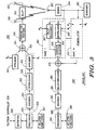
- FIG. 4 generally depicts a transmitter of a base-station-in CDMA communication with a mobile station using the orthogonal code assignment in accordance with the present invention. Those blocks between FIG. 3 and FIG. 4 which have common functionality also have common numbering.
- the blocks up to the interleaver 308 are similar in function to the prior art transmitter 300 of FIG. 3 , unless stated otherwise below.
- the interleaved data symbols 309 output from the interleaver 308 in FIG. 4 are input into two spreaders, spreader 312 and spreader 413.
- Each of these spreaders 312 and 413 convolves the interleaved symbols 309 with their orthogonal spreading sequence, namely Walsh code W i and Walsh code W A respectively.
- the spreading with the orthogonal spreading sequences (Walsh codes) is functionally equivalent as described above with reference to FIG. 3 .
- the encoder 304, interleaver 308 and two spreaders 312 and 413 comprise a duplicate traffic channel generator 402.
- Walsh code assignment block 403. divides a predetermined set of orthogonal codes into a plurality of subsets of orthogonal codes and assigns the subsets of orthogonal codes according to predetermined criterion.
- the predetermined criterion includes assigning the subsets of orthogonal codes to certain antennas servicing a common coverage area certain or to certain antennas within an antenna array.
- Each of the spreaders 312 and 413 outputs QPSK chips at a rate of 1.2288 megachips/second (i.e., 19.2 kilosymbols/second x 64).
- the spreader 310, summing note 314 and transmitter portion 316 of FIG. 4 operate functionally equivalent to the corresponding blocks of FIG. 3 .
- the spreader 411, summing node 415 and transmitter portion 417 also operate functionally equivalent to their corresponding blocks of FIG. 3 .
- Important to note is that, unlike the prior art transmitter 300 shown in FIG.
- each of the spreaders 310 and 411 used for spreading the pilot channel uses a spreading sequence (Walsh code W x and Walsh code Wy, respectively) which is orthogonal to one another in accordance with the invention.
- a receiver 490 receives the sum of both transmitted spread-spectrum signals 330 and 432 from the radio communication paths 330 and 432 via antenna 352 and is passed to demodulator 354 which functions as described above with reference to FIG. 3 .
- the QPSK sampled signal output from demodulator 354 is despread and detected by first finger RAKE receiver 360 as described above for FIG. 3 .
- the QPSK sampled signal output from demodulator 354 is despread and detected by a second finger RAKE receiver 470 as essentially described above for FIG.
- each of the RAKE receivers 360-370 have the pilot channel despread by the same Walsh code W x and the traffic channel despread by the same Walsh code W i .
- the searcher 450 searches for all signals spread with Walsh code W x transmitted by transmitter 400; in this instance, the searcher 450 would find one signal which corresponds to radio communication path 330. With this information, the searcher 450 assigns first finger RAKE receiver 360 to communication path 330 with pilot channel Walsh code W x and traffic channel Walsh code W i . A similar process is performed by the searcher 450 for signals spread with Walsh code W y transmitted by transmitter 400. In this instance, second finger RAKE receiver 470 is assigned to communication path 432 with pilot channel Walsh code Wy and traffic channel Walsh code W A .
- Having two pilot channels spread by different, orthogonal spreading sequences within a common coverage area allows one of the pilot channels to be used as the primary pilot channel for all mobile stations within the coverage area (as in the prior art) while the other pilot channel is used as a secondary pilot channel.
- the primary pilot channel which is used for acquisition and neighbor measurements by mobile station 106, is at a fixed, relatively high signal power level while the secondary pilot channel is at a much lower signal power level. This further acts to reduce unnecessary system interference when implementing forward link diversity in accordance with the invention.
- a correction prior to summing in summer 375 is required such that the signals entering the summer 375 from each of the RAKE receivers 360 and 470 are at substantially the same power level.
- One way to accomplish this is by appropriately reducing, via an attenuator, the signals exiting Rake receiver 360 or Rake receiver 470 in accordance with the power level difference at the transmitter 400. All processing after the summer 375 is the same as described above with reference to FIG. 3 .
- FIG. 6 generally depicts the assignment of orthogonal codes in the preferred embodiment to implement forward link transmit diversity in accordance with the invention.
- each antenna 218 and 222 have a separate group of dedicated Walsh codes assigned thereto.
- a primary pilot channel transmitted via antenna 218 is spread by Walsh code W x while a secondary pilot channel transmitted via antenna 222 is spread by a different Walsh code W y .
- all traffic channels for each of N separate users may each have separate Walsh codes assigned thereto on the secondary antenna 222.
- TCH N the TCH information
- mobile station 106 design of and knowledge contained within mobile station 106 is such that it properly performs a demodulation technique appropriate to whether a diversity signal is being transmitted or not. This includes full knowledge of what codes are used for all the pilots and traffic channels on each of the antennas. This may be facilitated through the use of messaging of information between the base-station 103 and mobile station 106. Methods to implement signaling of this information are known and are readily accomplished with messages provided in the IS-95 standard.
- implementation of forward link transmit diversity in accordance with the invention is the use of a different orthogonal spreading sequence to spread common pilot channels and TCHs for transmission on a second antenna.
- this can be accomplished by using two Walsh codes on antenna 218 which are not used on antenna 222.
- FIG. 7 Such an assignment of Walsh codes for the IS-95A example is shown in FIG. 7 .
- antenna 218 is assigned Walsh code 63 to spread the pilot channel Pilot A and thus act as a pilot channel for all mobile stations that are in the transmit diversity mode, while Walsh code 62 is used to spread the TCH information intended for mobile station 106 (designated TCH 106 in FIG. 7 ).
- Antenna 222 is then assigned Walsh code 0 to spread the pilot channel Pilot A and Walsh code 1 to spread the TCH 106 information intended for mobile station 106.
- Walsh code 0 in this example, thus acts as the common pilot channel for all mobile stations being served by or performing mobile assisted handoff (MAHO) on that coverage area, while Walsh code 1 conveys the TCH information to the particular mobile station.
- MAHO mobile assisted handoff
- any number of antennas can be assigned their own Walsh codes, e.g. as in an antenna array.
- eight antennas within an antenna array can be assigned eight Walsh codes which are themselves not assigned to any other antenna, and these eight Walsh codes can then be used to spread a pilot channel for each respective antenna, for example Pilot A .
- Mobile station 106 could then be assigned a single Walsh code for its traffic channel information TCH 106 that would then be transmitted on all of the antenna elements within the array. By setting the relative phases and amplitudes of this single Walsh code used to spread the TCH 106 information on the individual antenna elements, beamforming to direct transmit power directly at mobile station 106 is performed in accordance with the invention.
- base-station 103 informs mobile station 106 of the relative amplitudes and phases of the TCH 106 Walsh code that base-station 103 used to form the beam toward mobile station 106. This is accomplished by transmitting an appropriate message from base-station 103 to mobile station 106 including such information. Mobile station 106 would then determine the amplitude and phase of each of the pilot channels Pilot A spread with different Walsh codes o n the individual antennas. Given the relative amplitudes and phases of the pilot channels Pilot A spread with different Walsh codes and the message from base-station 103 which includes the relative amplitudes and phases of the TCH 106 Walsh code, mobile station 106 calculates a difference vector for each different pilot channel Walsh code. The sum of all of these difference vectors is then used by the mobile station 106 to perform coherent demodulation.
- Adequate signal to interference ratio necessary to improve reuse may be obtained when the same traffic channel Walsh code is used for multiple mobiles in the same sector by forming separate beams on each of the mobiles and transmitting them over the same antenna array.
- the pilot channel/Walsh code for each antenna could be shared among all mobile stations within the coverage area of interest (for example, sector A of FIG. 2 ).
- Another benefit resulting from the ability to assign separate pilot Walsh codes to a particular antenna is the ability to control the use of forward link transmit diversity.
- the only "control" available is to either transmit nothing to the mobile station 106 or transmit via both antenna 218 and antenna 222. This is due to the fact that some RAKE combining algorithms weight the combining strictly on the amount of pilot signal level received. Therefore, if multiple antennas are used having the pilot signal but no proper traffic channel is present, undesirable noise may be combined causing system degradation. However, there are certain modes and/or certain characteristics which occur during a communication where the transmission of both the original signal and its delayed version via antennas 218 and 222 is not beneficial.
- any more than three (3) rays transmitted to only a single mobile station 106 means that excess (unused) power is being transmitted by base-station 103, which degrades system performance.
- the Walsh code assignment of FIG. 6 in accordance with the invention is implemented, however, the use of forward link transmit diversity is controllable since the mobile station 106 can now be instructed, via appropriate messaging, as to which pilot channel Pilot A to listen via the different Walsh code assignment. As such, in the three-way handoff example described above, one of the signals being transmitted via forward link transmit diversity is removed since it does not help the mobile station 106 to better decode the signal.
- the addition of another ray in the forward link may only serve to degrade overall system performance. This information is readily available from the receiver (not shown) of the base-station 103 and can be input into the related functions block 407 for use by the Walsh code assignment block 403 of FIG. 4 .
- These modes and/or characteristics include the receive signal strength as determined by the mobile station 106 (or the base-station 103 is the transmission paths are assumed to be reciprocal), the pilot measurement information obtained in a pilot strength measurement message (PSMM), and the delay of a signal received at the mobile station 106. This last characteristic gives a direct indication of the distance of the mobile station 106 from the base-station 103 which could then be used to determine the high likelihood of an excessive amount of delay spread.
- PSMM pilot strength measurement message
- Still another mode and/or characteristic to control the use of forward link transmit diversity could be the location of the mobile station 106.
- a coverage area such as sector A could be pretested to determine the locations within the coverage area where forward link transmit diversity is known to provide degraded coverage to the mobile station.
- This pre-test information representing these locations can then be locally stored at the base-station 103 or at a central facility, such as the controller 209.
- the base-station 103 determines the location of the mobile station 106, a comparison can be made to the stored information to determine if the mobile station 106 is in one of the "known-bad" locations.
- forward link transmit diversity will not help the mobile station 106 and it will thus be disabled until the mobile station 106 moves into a more suitable area within the coverage area; if the mobile station is not in a "known-bad” location, then forward link transmit diversity is enabled.
- the mobile station 106 could be equipped to determine its own location and provide this information to the base-station 103 for the comparison.
- One such mechanism for the mobile station 106 to determine its own location is via the use of the Global Positioning System (GPS) or the like. If the mobile station 106 is capable of determining its own position, the pre-test information could also be downloaded to the mobile station 106 and stored locally therein. In this configuration, the mobile station 106 itself could determine that it is in a "known-bad” or "known-good” location, and disable/enable reception of one of the pilot channels spread with orthogonal spreading codes accordingly in accordance with the invention.
- GPS Global Positioning System
Landscapes
- Engineering & Computer Science (AREA)
- Computer Networks & Wireless Communication (AREA)
- Signal Processing (AREA)
- Mobile Radio Communication Systems (AREA)
- Digital Transmission Methods That Use Modulated Carrier Waves (AREA)
Applications Claiming Priority (3)
| Application Number | Priority Date | Filing Date | Title |
|---|---|---|---|
| US904204 | 1997-07-31 | ||
| US08/904,204 US6038263A (en) | 1997-07-31 | 1997-07-31 | Method and apparatus for transmitting signals in a communication system |
| PCT/US1998/014560 WO1999007090A1 (en) | 1997-07-31 | 1998-07-14 | Method and apparatus for transmitting signals in a communication system |
Publications (3)
| Publication Number | Publication Date |
|---|---|
| EP1228590A1 EP1228590A1 (en) | 2002-08-07 |
| EP1228590A4 EP1228590A4 (en) | 2006-09-06 |
| EP1228590B1 true EP1228590B1 (en) | 2011-04-13 |
Family
ID=25418764
Family Applications (1)
| Application Number | Title | Priority Date | Filing Date |
|---|---|---|---|
| EP98967150A Expired - Lifetime EP1228590B1 (en) | 1997-07-31 | 1998-07-14 | Method and apparatus for transmitting signals in a communication system |
Country Status (13)
| Country | Link |
|---|---|
| US (1) | US6038263A (pt) |
| EP (1) | EP1228590B1 (pt) |
| JP (1) | JP2001512921A (pt) |
| KR (1) | KR100356248B1 (pt) |
| CN (2) | CN101820325A (pt) |
| AR (1) | AR013648A1 (pt) |
| AU (1) | AU732494B2 (pt) |
| BR (1) | BRPI9810855B1 (pt) |
| CA (1) | CA2298647C (pt) |
| DE (1) | DE69842223D1 (pt) |
| IL (1) | IL133862A0 (pt) |
| RU (1) | RU2211536C2 (pt) |
| WO (1) | WO1999007090A1 (pt) |
Families Citing this family (124)
| Publication number | Priority date | Publication date | Assignee | Title |
|---|---|---|---|---|
| US6510147B1 (en) | 1997-07-15 | 2003-01-21 | Hughes Electronics Corporation | Method and apparatus for orthogonally overlaying variable chip rate spread spectrum signals |
| US6396822B1 (en) * | 1997-07-15 | 2002-05-28 | Hughes Electronics Corporation | Method and apparatus for encoding data for transmission in a communication system |
| US6141542A (en) * | 1997-07-31 | 2000-10-31 | Motorola, Inc. | Method and apparatus for controlling transmit diversity in a communication system |
| US6285655B1 (en) * | 1997-09-08 | 2001-09-04 | Qualcomm Inc. | Method and apparatus for providing orthogonal spot beams, sectors, and picocells |
| US6185258B1 (en) * | 1997-09-16 | 2001-02-06 | At&T Wireless Services Inc. | Transmitter diversity technique for wireless communications |
| DE69833780T2 (de) | 1997-10-31 | 2006-08-17 | Cingular Wireless Ii Llc. | Maximal-wahrscheinlichkeitsdetektion von verketteten raum/zeit kodes für schnurlose anwendungen mit sender-diversity |
| US9118387B2 (en) * | 1997-11-03 | 2015-08-25 | Qualcomm Incorporated | Pilot reference transmission for a wireless communication system |
| US7184426B2 (en) * | 2002-12-12 | 2007-02-27 | Qualcomm, Incorporated | Method and apparatus for burst pilot for a time division multiplex system |
| US6795508B1 (en) * | 1997-12-02 | 2004-09-21 | Qualcomm, Incorporated | Method and apparatus for obtaining transmit diversity using switched antennas |
| US6188736B1 (en) | 1997-12-23 | 2001-02-13 | At&T Wireless Svcs. Inc. | Near-optimal low-complexity decoding of space-time codes for fixed wireless applications |
| KR100287429B1 (ko) * | 1997-12-31 | 2001-04-16 | 서평원 | 부호 분할 방식의 채널 할당방법 및 장치[Method and apparatus for channel-assigning of Code division duplexing] |
| US7536624B2 (en) * | 2002-01-03 | 2009-05-19 | The Directv Group, Inc. | Sets of rate-compatible universal turbo codes nearly optimized over various rates and interleaver sizes |
| US6169752B1 (en) * | 1998-02-26 | 2001-01-02 | Lsi Logic Corporation | Method and system for preventing information losses during alternative frequency searches |
| JP3266091B2 (ja) | 1998-03-04 | 2002-03-18 | 日本電気株式会社 | セルラシステム |
| US6208615B1 (en) * | 1998-05-29 | 2001-03-27 | Northern Telecom Limited | Broadband wireless access based on code division parallel access |
| KR20000014423A (ko) * | 1998-08-17 | 2000-03-15 | 윤종용 | 부호분할다중접속 통신시스템의 통신제어장치 및 방법 |
| US6459740B1 (en) | 1998-09-17 | 2002-10-01 | At&T Wireless Services, Inc. | Maximum ratio transmission |
| US6519456B2 (en) * | 1998-10-14 | 2003-02-11 | Qualcomm Incorporated | Softer handoff in a base station employing virtual channel elements |
| US6728202B1 (en) * | 1998-12-24 | 2004-04-27 | Agere Systems Inc. | Code division multiplex satellite broadcasting system |
| US6317411B1 (en) * | 1999-02-22 | 2001-11-13 | Motorola, Inc. | Method and system for transmitting and receiving signals transmitted from an antenna array with transmit diversity techniques |
| JP4955850B2 (ja) * | 1999-04-08 | 2012-06-20 | テキサス インスツルメンツ インコーポレイテッド | Wcdmaのためのダイバーシティ検出 |
| US6515978B1 (en) * | 1999-04-19 | 2003-02-04 | Lucent Technologies Inc. | Methods and apparatus for downlink diversity in CDMA using Walsh codes |
| US6560536B1 (en) | 1999-07-12 | 2003-05-06 | Eagle-Eye, Inc. | System and method for rapid telepositioning |
| US20040143392A1 (en) * | 1999-07-12 | 2004-07-22 | Skybitz, Inc. | System and method for fast acquisition reporting using communication satellite range measurement |
| US6480788B2 (en) | 1999-07-12 | 2002-11-12 | Eagle-Eye, Inc. | System and method for fast acquisition reporting using communication satellite range measurement |
| US8255149B2 (en) | 1999-07-12 | 2012-08-28 | Skybitz, Inc. | System and method for dual-mode location determination |
| US6747948B1 (en) * | 1999-08-11 | 2004-06-08 | Lucent Technologies Inc. | Interleaver scheme in an OFDM system with multiple-stream data sources |
| JP3583343B2 (ja) * | 1999-11-29 | 2004-11-04 | 松下電器産業株式会社 | 通信端末装置、基地局装置および送信電力制御方法 |
| JP2009038817A (ja) * | 2000-04-06 | 2009-02-19 | Ntt Docomo Inc | Cdmaセルラ方式における同期捕捉方法およびその装置 |
| FI20001160A (fi) * | 2000-05-15 | 2001-11-16 | Nokia Networks Oy | Pilottisignaalin toteuttamismenetelmä |
| ATE311045T1 (de) * | 2000-05-25 | 2005-12-15 | Samsung Electronics Co Ltd | Vorrichtung und verfahren f r bertragungs- diversity durch verwendung von mehr als zwei antennen |
| JP3402363B2 (ja) * | 2000-06-13 | 2003-05-06 | 日本電気株式会社 | 送信ダイバーシチ方式送信機における遅延時間制御方式。 |
| JP2004506219A (ja) | 2000-08-09 | 2004-02-26 | スカイビッツ,インコーポレイテッド | Gps受信機におけるコード位相ならびにキャリア周波数の高速捕捉システム並びに方法 |
| US7295509B2 (en) * | 2000-09-13 | 2007-11-13 | Qualcomm, Incorporated | Signaling method in an OFDM multiple access system |
| US9130810B2 (en) | 2000-09-13 | 2015-09-08 | Qualcomm Incorporated | OFDM communications methods and apparatus |
| AU2001288963A1 (en) * | 2000-09-18 | 2002-04-02 | Skybitz, Inc | System and method for fast code phase and carrier frequency acquisition in gps receiver |
| US6973098B1 (en) * | 2000-10-25 | 2005-12-06 | Qualcomm, Incorporated | Method and apparatus for determining a data rate in a high rate packet data wireless communications system |
| US7068683B1 (en) | 2000-10-25 | 2006-06-27 | Qualcomm, Incorporated | Method and apparatus for high rate packet data and low delay data transmissions |
| US20020110108A1 (en) | 2000-12-07 | 2002-08-15 | Younglok Kim | Simple block space time transmit diversity using multiple spreading codes |
| JP3679000B2 (ja) * | 2000-12-21 | 2005-08-03 | 松下電器産業株式会社 | 無線送信装置及び無線送信方法 |
| GB2371947B (en) * | 2001-02-01 | 2005-02-23 | Fujitsu Ltd | Communications systems |
| CN1299442C (zh) * | 2001-04-05 | 2007-02-07 | 北方电讯网络有限公司 | 采用多个码和多个天线的用于无线通信系统的发射机 |
| US6711124B2 (en) * | 2001-05-25 | 2004-03-23 | Ericsson Inc. | Time interval based channel estimation with transmit diversity |
| CN100403596C (zh) * | 2001-11-29 | 2008-07-16 | 美商内数位科技公司 | 用于多路径衰减信道的有效多输入多输出系统 |
| US20030108087A1 (en) * | 2001-12-06 | 2003-06-12 | Itzhak Shperling | Method and base station for providing transmit diversity |
| AU2004214806A1 (en) * | 2003-02-24 | 2004-09-10 | Qualcomm Incorporated | Pilot signals for use in multi-sector cells |
| US7218948B2 (en) | 2003-02-24 | 2007-05-15 | Qualcomm Incorporated | Method of transmitting pilot tones in a multi-sector cell, including null pilot tones, for generating channel quality indicators |
| US9544860B2 (en) | 2003-02-24 | 2017-01-10 | Qualcomm Incorporated | Pilot signals for use in multi-sector cells |
| US9661519B2 (en) | 2003-02-24 | 2017-05-23 | Qualcomm Incorporated | Efficient reporting of information in a wireless communication system |
| US8811348B2 (en) | 2003-02-24 | 2014-08-19 | Qualcomm Incorporated | Methods and apparatus for generating, communicating, and/or using information relating to self-noise |
| US8559406B2 (en) * | 2003-06-03 | 2013-10-15 | Qualcomm Incorporated | Method and apparatus for communications of data in a communication system |
| US7450549B2 (en) * | 2003-08-05 | 2008-11-11 | Via Telecom Co., Ltd. | Pilot signal enhancements for a wireless communication system |
| KR20050027679A (ko) * | 2003-09-16 | 2005-03-21 | 삼성전자주식회사 | 이동통신시스템에서 고속 패킷 데이터 송/수신장치 및 방법 |
| US8077691B2 (en) * | 2004-03-05 | 2011-12-13 | Qualcomm Incorporated | Pilot transmission and channel estimation for MISO and MIMO receivers in a multi-antenna system |
| US7554944B2 (en) | 2004-03-09 | 2009-06-30 | Avage Inc. | Signal transmitting method and device for carrying out said method |
| US9137822B2 (en) | 2004-07-21 | 2015-09-15 | Qualcomm Incorporated | Efficient signaling over access channel |
| US9148256B2 (en) * | 2004-07-21 | 2015-09-29 | Qualcomm Incorporated | Performance based rank prediction for MIMO design |
| ES2294631T3 (es) * | 2005-02-25 | 2008-04-01 | Nemerix Sa | Discriminador de frecuencia lineal half bin. |
| US9246560B2 (en) | 2005-03-10 | 2016-01-26 | Qualcomm Incorporated | Systems and methods for beamforming and rate control in a multi-input multi-output communication systems |
| US9154211B2 (en) | 2005-03-11 | 2015-10-06 | Qualcomm Incorporated | Systems and methods for beamforming feedback in multi antenna communication systems |
| US8446892B2 (en) * | 2005-03-16 | 2013-05-21 | Qualcomm Incorporated | Channel structures for a quasi-orthogonal multiple-access communication system |
| US9520972B2 (en) * | 2005-03-17 | 2016-12-13 | Qualcomm Incorporated | Pilot signal transmission for an orthogonal frequency division wireless communication system |
| US9143305B2 (en) | 2005-03-17 | 2015-09-22 | Qualcomm Incorporated | Pilot signal transmission for an orthogonal frequency division wireless communication system |
| US9461859B2 (en) * | 2005-03-17 | 2016-10-04 | Qualcomm Incorporated | Pilot signal transmission for an orthogonal frequency division wireless communication system |
| US9184870B2 (en) * | 2005-04-01 | 2015-11-10 | Qualcomm Incorporated | Systems and methods for control channel signaling |
| DE102005017080B4 (de) * | 2005-04-08 | 2007-07-26 | Accelant Communications Gmbh | Übertragungsverfahren in einem Funksystem mit mehreren Sende-/Empfangszweigen in der Basisstation |
| US9036538B2 (en) * | 2005-04-19 | 2015-05-19 | Qualcomm Incorporated | Frequency hopping design for single carrier FDMA systems |
| US9408220B2 (en) | 2005-04-19 | 2016-08-02 | Qualcomm Incorporated | Channel quality reporting for adaptive sectorization |
| US8929195B1 (en) * | 2005-05-11 | 2015-01-06 | Sprint Spectrum L.P. | Method and system of reusing walsh codes to increase forward channel capacity |
| US8565194B2 (en) | 2005-10-27 | 2013-10-22 | Qualcomm Incorporated | Puncturing signaling channel for a wireless communication system |
| US8879511B2 (en) | 2005-10-27 | 2014-11-04 | Qualcomm Incorporated | Assignment acknowledgement for a wireless communication system |
| US8611284B2 (en) | 2005-05-31 | 2013-12-17 | Qualcomm Incorporated | Use of supplemental assignments to decrement resources |
| US8462859B2 (en) * | 2005-06-01 | 2013-06-11 | Qualcomm Incorporated | Sphere decoding apparatus |
| US8599945B2 (en) | 2005-06-16 | 2013-12-03 | Qualcomm Incorporated | Robust rank prediction for a MIMO system |
| US9179319B2 (en) | 2005-06-16 | 2015-11-03 | Qualcomm Incorporated | Adaptive sectorization in cellular systems |
| US8036296B2 (en) * | 2006-09-28 | 2011-10-11 | Broadcom Corporation | Method and system for achieving space and time diversity gain |
| US8885628B2 (en) | 2005-08-08 | 2014-11-11 | Qualcomm Incorporated | Code division multiplexing in a single-carrier frequency division multiple access system |
| US9209956B2 (en) | 2005-08-22 | 2015-12-08 | Qualcomm Incorporated | Segment sensitive scheduling |
| US20070041457A1 (en) | 2005-08-22 | 2007-02-22 | Tamer Kadous | Method and apparatus for providing antenna diversity in a wireless communication system |
| US8644292B2 (en) * | 2005-08-24 | 2014-02-04 | Qualcomm Incorporated | Varied transmission time intervals for wireless communication system |
| US9136974B2 (en) | 2005-08-30 | 2015-09-15 | Qualcomm Incorporated | Precoding and SDMA support |
| US8989084B2 (en) | 2005-10-14 | 2015-03-24 | Qualcomm Incorporated | Methods and apparatus for broadcasting loading information corresponding to neighboring base stations |
| US9191840B2 (en) | 2005-10-14 | 2015-11-17 | Qualcomm Incorporated | Methods and apparatus for determining, communicating and using information which can be used for interference control |
| US9088384B2 (en) * | 2005-10-27 | 2015-07-21 | Qualcomm Incorporated | Pilot symbol transmission in wireless communication systems |
| US8693405B2 (en) | 2005-10-27 | 2014-04-08 | Qualcomm Incorporated | SDMA resource management |
| US9172453B2 (en) | 2005-10-27 | 2015-10-27 | Qualcomm Incorporated | Method and apparatus for pre-coding frequency division duplexing system |
| US9225488B2 (en) | 2005-10-27 | 2015-12-29 | Qualcomm Incorporated | Shared signaling channel |
| US9210651B2 (en) | 2005-10-27 | 2015-12-08 | Qualcomm Incorporated | Method and apparatus for bootstraping information in a communication system |
| US8477684B2 (en) | 2005-10-27 | 2013-07-02 | Qualcomm Incorporated | Acknowledgement of control messages in a wireless communication system |
| US8582509B2 (en) * | 2005-10-27 | 2013-11-12 | Qualcomm Incorporated | Scalable frequency band operation in wireless communication systems |
| US8045512B2 (en) | 2005-10-27 | 2011-10-25 | Qualcomm Incorporated | Scalable frequency band operation in wireless communication systems |
| US9144060B2 (en) | 2005-10-27 | 2015-09-22 | Qualcomm Incorporated | Resource allocation for shared signaling channels |
| US9225416B2 (en) | 2005-10-27 | 2015-12-29 | Qualcomm Incorporated | Varied signaling channels for a reverse link in a wireless communication system |
| US8582548B2 (en) | 2005-11-18 | 2013-11-12 | Qualcomm Incorporated | Frequency division multiple access schemes for wireless communication |
| US7893873B2 (en) * | 2005-12-20 | 2011-02-22 | Qualcomm Incorporated | Methods and systems for providing enhanced position location in wireless communications |
| US20070249360A1 (en) | 2005-12-22 | 2007-10-25 | Arnab Das | Methods and aparatus related to determining, communicating, and/or using delay information in a wireless communications system |
| US20070149132A1 (en) | 2005-12-22 | 2007-06-28 | Junyl Li | Methods and apparatus related to selecting control channel reporting formats |
| US9125092B2 (en) | 2005-12-22 | 2015-09-01 | Qualcomm Incorporated | Methods and apparatus for reporting and/or using control information |
| US9451491B2 (en) | 2005-12-22 | 2016-09-20 | Qualcomm Incorporated | Methods and apparatus relating to generating and transmitting initial and additional control information report sets in a wireless system |
| US9119220B2 (en) | 2005-12-22 | 2015-08-25 | Qualcomm Incorporated | Methods and apparatus for communicating backlog related information |
| US9125093B2 (en) | 2005-12-22 | 2015-09-01 | Qualcomm Incorporated | Methods and apparatus related to custom control channel reporting formats |
| US9473265B2 (en) | 2005-12-22 | 2016-10-18 | Qualcomm Incorporated | Methods and apparatus for communicating information utilizing a plurality of dictionaries |
| US9137072B2 (en) | 2005-12-22 | 2015-09-15 | Qualcomm Incorporated | Methods and apparatus for communicating control information |
| US8437251B2 (en) | 2005-12-22 | 2013-05-07 | Qualcomm Incorporated | Methods and apparatus for communicating transmission backlog information |
| US9148795B2 (en) | 2005-12-22 | 2015-09-29 | Qualcomm Incorporated | Methods and apparatus for flexible reporting of control information |
| US8514771B2 (en) | 2005-12-22 | 2013-08-20 | Qualcomm Incorporated | Methods and apparatus for communicating and/or using transmission power information |
| US9572179B2 (en) | 2005-12-22 | 2017-02-14 | Qualcomm Incorporated | Methods and apparatus for communicating transmission backlog information |
| US9338767B2 (en) | 2005-12-22 | 2016-05-10 | Qualcomm Incorporated | Methods and apparatus of implementing and/or using a dedicated control channel |
| US20070243882A1 (en) | 2006-04-12 | 2007-10-18 | Qualcomm Incorporated | Method and apparatus for locating a wireless local area network associated with a wireless wide area network |
| US7860147B2 (en) * | 2006-08-16 | 2010-12-28 | Harris Corporation | Method of communicating and associated transmitter using coded orthogonal frequency division multiplexing (COFDM) |
| US7903749B2 (en) * | 2006-08-16 | 2011-03-08 | Harris Corporation | System and method for applying frequency domain spreading to multi-carrier communications signals |
| US7649951B2 (en) * | 2006-08-16 | 2010-01-19 | Harris Corporation | System and method for communicating data using symbol-based randomized orthogonal frequency division multiplexing (OFDM) with applied frequency domain spreading |
| US7813433B2 (en) * | 2006-08-16 | 2010-10-12 | Harris Corporation | System and method for communicating data using symbol-based randomized orthogonal frequency division multiplexing (OFDM) with selected subcarriers turned on or off |
| US7751488B2 (en) * | 2006-08-16 | 2010-07-06 | Harris Corporation | System and method for communicating data using symbol-based randomized orthogonal frequency division multiplexing (OFDM) |
| EP2082492A4 (en) * | 2006-11-13 | 2015-12-16 | Ericsson Telefon Ab L M | METHOD AND ARRANGEMENT FOR PILOT MODULE CONTROL SIGNALING IN MIMO SYSTEMS |
| US8767872B2 (en) * | 2007-05-18 | 2014-07-01 | Qualcomm Incorporated | Pilot structures for ACK and CQI in a wireless communication system |
| US8538335B2 (en) * | 2007-12-07 | 2013-09-17 | Samsung Electronics Co., Ltd | Physical broadcast channel (PBCH) transmission for reliable detection of antenna configuration |
| CN102224687B (zh) * | 2008-09-22 | 2014-10-29 | 岩星比德科有限公司 | 用于pucch的空间代码传送分集的方法和系统 |
| US8811200B2 (en) * | 2009-09-22 | 2014-08-19 | Qualcomm Incorporated | Physical layer metrics to support adaptive station-dependent channel state information feedback rate in multi-user communication systems |
| WO2011126447A1 (en) | 2010-04-07 | 2011-10-13 | Telefonaktiebolaget L M Ericsson (Publ) | A precoder structure for mimo precoding |
| RU2464193C2 (ru) * | 2010-12-24 | 2012-10-20 | Государственное образовательное учреждение высшего профессионального образования "Московский государственный университет путей сообщения" (МИИТ) | Система железнодорожной радиосвязи |
| ES2654666T3 (es) | 2013-07-02 | 2018-02-14 | Huawei Technologies Co., Ltd. | Método y aparato de procesamiento de información |
| JP2018207333A (ja) * | 2017-06-06 | 2018-12-27 | 富士通株式会社 | 基地局、無線端末、無線通信システム、及び通信制御方法 |
| CN110351842B (zh) * | 2018-04-04 | 2023-10-17 | 北京三星通信技术研究有限公司 | 符号映射方法及用户设备 |
Family Cites Families (13)
| Publication number | Priority date | Publication date | Assignee | Title |
|---|---|---|---|---|
| US5103459B1 (en) * | 1990-06-25 | 1999-07-06 | Qualcomm Inc | System and method for generating signal waveforms in a cdma cellular telephone system |
| US5136612A (en) * | 1990-12-31 | 1992-08-04 | At&T Bell Laboratories | Method and apparatus for reducing effects of multiple access interference in a radio receiver in a code division multiple access communication system |
| US5305353A (en) * | 1992-05-29 | 1994-04-19 | At&T Bell Laboratories | Method and apparatus for providing time diversity |
| US5812542A (en) * | 1996-03-18 | 1998-09-22 | Motorola, Inc. | Method for determining weighting coefficients in a CDMA radio receiver |
| US5414728A (en) * | 1993-11-01 | 1995-05-09 | Qualcomm Incorporated | Method and apparatus for bifurcating signal transmission over in-phase and quadrature phase spread spectrum communication channels |
| US5418813A (en) * | 1993-12-06 | 1995-05-23 | Motorola, Inc. | Method and apparatus for creating a composite waveform |
| US5673260A (en) * | 1994-02-09 | 1997-09-30 | Ntt Mobile Communications Network Inc. | Method and system for CDMA mobile communication |
| US5602833A (en) * | 1994-12-19 | 1997-02-11 | Qualcomm Incorporated | Method and apparatus for using Walsh shift keying in a spread spectrum communication system |
| JPH08195703A (ja) * | 1995-01-17 | 1996-07-30 | Toshiba Corp | 無線通信装置 |
| US5623485A (en) * | 1995-02-21 | 1997-04-22 | Lucent Technologies Inc. | Dual mode code division multiple access communication system and method |
| ZA961025B (en) * | 1995-02-28 | 1996-07-16 | Qualcomm Inc | Method and apparatus for providing variable rate data in a communications system using non-orthogonal overflow channels |
| US5896368A (en) * | 1995-05-01 | 1999-04-20 | Telefonaktiebolaget Lm Ericsson | Multi-code compressed mode DS-CDMA systems and methods |
| US5781541A (en) * | 1995-05-03 | 1998-07-14 | Bell Atlantic Network Services, Inc. | CDMA system having time-distributed transmission paths for multipath reception |
-
1997
- 1997-07-31 US US08/904,204 patent/US6038263A/en not_active Expired - Lifetime
-
1998
- 1998-07-14 IL IL13386298A patent/IL133862A0/xx not_active IP Right Cessation
- 1998-07-14 KR KR1020007001036A patent/KR100356248B1/ko not_active IP Right Cessation
- 1998-07-14 WO PCT/US1998/014560 patent/WO1999007090A1/en active IP Right Grant
- 1998-07-14 CA CA002298647A patent/CA2298647C/en not_active Expired - Lifetime
- 1998-07-14 CN CN201010121349A patent/CN101820325A/zh active Pending
- 1998-07-14 CN CN98807782A patent/CN1265793A/zh active Pending
- 1998-07-14 EP EP98967150A patent/EP1228590B1/en not_active Expired - Lifetime
- 1998-07-14 JP JP2000505701A patent/JP2001512921A/ja active Pending
- 1998-07-14 RU RU2000104849/09A patent/RU2211536C2/ru active
- 1998-07-14 DE DE69842223T patent/DE69842223D1/de not_active Expired - Lifetime
- 1998-07-14 AU AU84851/98A patent/AU732494B2/en not_active Expired
- 1998-07-14 BR BRPI9810855A patent/BRPI9810855B1/pt active IP Right Grant
- 1998-07-30 AR ARP980103767A patent/AR013648A1/es active IP Right Grant
Also Published As
| Publication number | Publication date |
|---|---|
| AR013648A1 (es) | 2001-01-10 |
| AU732494B2 (en) | 2001-04-26 |
| RU2211536C2 (ru) | 2003-08-27 |
| CA2298647C (en) | 2003-01-21 |
| EP1228590A4 (en) | 2006-09-06 |
| CN1265793A (zh) | 2000-09-06 |
| JP2001512921A (ja) | 2001-08-28 |
| BRPI9810855B1 (pt) | 2015-12-08 |
| AU8485198A (en) | 1999-02-22 |
| KR20010022451A (ko) | 2001-03-15 |
| IL133862A0 (en) | 2001-04-30 |
| WO1999007090A1 (en) | 1999-02-11 |
| BR9810855A (pt) | 2000-07-25 |
| CN101820325A (zh) | 2010-09-01 |
| US6038263A (en) | 2000-03-14 |
| EP1228590A1 (en) | 2002-08-07 |
| CA2298647A1 (en) | 1999-02-11 |
| KR100356248B1 (ko) | 2002-10-12 |
| DE69842223D1 (de) | 2011-05-26 |
Similar Documents
| Publication | Publication Date | Title |
|---|---|---|
| EP1228590B1 (en) | Method and apparatus for transmitting signals in a communication system | |
| US6141542A (en) | Method and apparatus for controlling transmit diversity in a communication system | |
| EP1020039B1 (en) | Apparatus and method for transmitting signals in a communication system | |
| KR100920407B1 (ko) | Cdma 통신 시스템에서 채널화 코드를 시간 공유하기 위한 방법 및 장치 | |
| US6424619B2 (en) | High data rate CDMA wireless communication system | |
| US6285655B1 (en) | Method and apparatus for providing orthogonal spot beams, sectors, and picocells | |
| US6359868B1 (en) | Method and apparatus for transmitting and receiving data multiplexed onto multiple code channels, frequencies and base stations | |
| EP0926843B1 (en) | Method and system for operating a cellular system having beamforming antennas | |
| EP1147618B1 (en) | Method and apparatus for reducing peak-to-average ratio in a cdma communication system | |
| JP2004511176A (ja) | 移動通信システムにおけるdschの電力制御のための装置及び方法 | |
| EP1210834A1 (en) | Method and system for initiating idle handoff in a wireless communications system | |
| Herscovici et al. | Potentials of smart antennas in CDMA systems and uplink improvements | |
| KR100532311B1 (ko) | 이동통신 시스템에서 송신 다이버시티 복조를 위한 장치및 방법 | |
| JP4607397B2 (ja) | レート判定改善のためのフレームエネルギー基準使用のための方法および装置 | |
| Lin et al. | IS-95 north American standard-A CDMA based digital cellular system | |
| WO2000008771A1 (en) | Method and apparatus for rotating modulation symbol indices |
Legal Events
| Date | Code | Title | Description |
|---|---|---|---|
| PUAI | Public reference made under article 153(3) epc to a published international application that has entered the european phase |
Free format text: ORIGINAL CODE: 0009012 |
|
| 17P | Request for examination filed |
Effective date: 20000229 |
|
| AK | Designated contracting states |
Kind code of ref document: A1 Designated state(s): DE FI FR GB SE |
|
| RIN1 | Information on inventor provided before grant (corrected) |
Inventor name: RAZANSKI, WALTER, J., JR. Inventor name: KOTZIN, MICHAEL, D. |
|
| A4 | Supplementary search report drawn up and despatched |
Effective date: 20060803 |
|
| RIC1 | Information provided on ipc code assigned before grant |
Ipc: H04J 11/00 20060101ALI20060728BHEP Ipc: H04B 7/06 20060101ALI20060728BHEP Ipc: H04L 27/30 20060101ALI20060728BHEP Ipc: H04K 1/00 20060101ALI20060728BHEP Ipc: H04B 7/10 20060101ALI20060728BHEP Ipc: H04B 15/00 20060101AFI20020411BHEP |
|
| 17Q | First examination report despatched |
Effective date: 20070820 |
|
| GRAP | Despatch of communication of intention to grant a patent |
Free format text: ORIGINAL CODE: EPIDOSNIGR1 |
|
| RAP1 | Party data changed (applicant data changed or rights of an application transferred) |
Owner name: MOTOROLA MOBILITY, INC. |
|
| GRAS | Grant fee paid |
Free format text: ORIGINAL CODE: EPIDOSNIGR3 |
|
| GRAA | (expected) grant |
Free format text: ORIGINAL CODE: 0009210 |
|
| REG | Reference to a national code |
Ref country code: DE Ref legal event code: R081 Ref document number: 69842223 Country of ref document: DE Owner name: GOOGLE TECHNOLOGY HOLDINGS LLC, MOUNTAIN VIEW, US Free format text: FORMER OWNER: MOTOROLA, INC., SCHAUMBURG, ILL., US |
|
| AK | Designated contracting states |
Kind code of ref document: B1 Designated state(s): DE FI FR GB SE |
|
| REG | Reference to a national code |
Ref country code: GB Ref legal event code: FG4D |
|
| REF | Corresponds to: |
Ref document number: 69842223 Country of ref document: DE Date of ref document: 20110526 Kind code of ref document: P |
|
| REG | Reference to a national code |
Ref country code: DE Ref legal event code: R096 Ref document number: 69842223 Country of ref document: DE Effective date: 20110526 |
|
| PG25 | Lapsed in a contracting state [announced via postgrant information from national office to epo] |
Ref country code: SE Free format text: LAPSE BECAUSE OF FAILURE TO SUBMIT A TRANSLATION OF THE DESCRIPTION OR TO PAY THE FEE WITHIN THE PRESCRIBED TIME-LIMIT Effective date: 20110413 |
|
| PG25 | Lapsed in a contracting state [announced via postgrant information from national office to epo] |
Ref country code: FI Free format text: LAPSE BECAUSE OF FAILURE TO SUBMIT A TRANSLATION OF THE DESCRIPTION OR TO PAY THE FEE WITHIN THE PRESCRIBED TIME-LIMIT Effective date: 20110413 |
|
| PLBE | No opposition filed within time limit |
Free format text: ORIGINAL CODE: 0009261 |
|
| STAA | Information on the status of an ep patent application or granted ep patent |
Free format text: STATUS: NO OPPOSITION FILED WITHIN TIME LIMIT |
|
| 26N | No opposition filed |
Effective date: 20120116 |
|
| REG | Reference to a national code |
Ref country code: DE Ref legal event code: R097 Ref document number: 69842223 Country of ref document: DE Effective date: 20120116 |
|
| REG | Reference to a national code |
Ref country code: DE Ref legal event code: R082 Ref document number: 69842223 Country of ref document: DE Representative=s name: BETTEN & RESCH PATENT- UND RECHTSANWAELTE PART, DE Ref country code: DE Ref legal event code: R082 Ref document number: 69842223 Country of ref document: DE Representative=s name: KASTEL PATENTANWAELTE, DE |
|
| REG | Reference to a national code |
Ref country code: FR Ref legal event code: PLFP Year of fee payment: 19 |
|
| REG | Reference to a national code |
Ref country code: FR Ref legal event code: PLFP Year of fee payment: 20 |
|
| REG | Reference to a national code |
Ref country code: GB Ref legal event code: 732E Free format text: REGISTERED BETWEEN 20170831 AND 20170906 |
|
| PGFP | Annual fee paid to national office [announced via postgrant information from national office to epo] |
Ref country code: DE Payment date: 20170727 Year of fee payment: 20 Ref country code: FR Payment date: 20170726 Year of fee payment: 20 Ref country code: GB Payment date: 20170727 Year of fee payment: 20 |
|
| REG | Reference to a national code |
Ref country code: FR Ref legal event code: TP Owner name: GOOGLE TECHNOLOGY HOLDINGS LLC, US Effective date: 20171214 Ref country code: FR Ref legal event code: CD Owner name: GOOGLE TECHNOLOGY HOLDINGS LLC, US Effective date: 20171214 |
|
| REG | Reference to a national code |
Ref country code: DE Ref legal event code: R082 Ref document number: 69842223 Country of ref document: DE Representative=s name: BETTEN & RESCH PATENT- UND RECHTSANWAELTE PART, DE Ref country code: DE Ref legal event code: R081 Ref document number: 69842223 Country of ref document: DE Owner name: GOOGLE TECHNOLOGY HOLDINGS LLC, MOUNTAIN VIEW, US Free format text: FORMER OWNER: MOTOROLA MOBILITY, INC., LIBERTYVILLE, ILL., US |
|
| REG | Reference to a national code |
Ref country code: DE Ref legal event code: R071 Ref document number: 69842223 Country of ref document: DE |
|
| REG | Reference to a national code |
Ref country code: GB Ref legal event code: PE20 Expiry date: 20180713 |
|
| PG25 | Lapsed in a contracting state [announced via postgrant information from national office to epo] |
Ref country code: GB Free format text: LAPSE BECAUSE OF EXPIRATION OF PROTECTION Effective date: 20180713 |
|
| P01 | Opt-out of the competence of the unified patent court (upc) registered |
Effective date: 20230516 |