EP1227936B1 - Digital media cutter - Google Patents
Digital media cutter Download PDFInfo
- Publication number
- EP1227936B1 EP1227936B1 EP00992333A EP00992333A EP1227936B1 EP 1227936 B1 EP1227936 B1 EP 1227936B1 EP 00992333 A EP00992333 A EP 00992333A EP 00992333 A EP00992333 A EP 00992333A EP 1227936 B1 EP1227936 B1 EP 1227936B1
- Authority
- EP
- European Patent Office
- Prior art keywords
- media
- laser light
- ink
- carriage
- Prior art date
- Legal status (The legal status is an assumption and is not a legal conclusion. Google has not performed a legal analysis and makes no representation as to the accuracy of the status listed.)
- Expired - Lifetime
Links
Images


Classifications
-
- B—PERFORMING OPERATIONS; TRANSPORTING
- B23—MACHINE TOOLS; METAL-WORKING NOT OTHERWISE PROVIDED FOR
- B23K—SOLDERING OR UNSOLDERING; WELDING; CLADDING OR PLATING BY SOLDERING OR WELDING; CUTTING BY APPLYING HEAT LOCALLY, e.g. FLAME CUTTING; WORKING BY LASER BEAM
- B23K26/00—Working by laser beam, e.g. welding, cutting or boring
- B23K26/02—Positioning or observing the workpiece, e.g. with respect to the point of impact; Aligning, aiming or focusing the laser beam
- B23K26/06—Shaping the laser beam, e.g. by masks or multi-focusing
- B23K26/0604—Shaping the laser beam, e.g. by masks or multi-focusing by a combination of beams
- B23K26/0608—Shaping the laser beam, e.g. by masks or multi-focusing by a combination of beams in the same heat affected zone [HAZ]
-
- B—PERFORMING OPERATIONS; TRANSPORTING
- B23—MACHINE TOOLS; METAL-WORKING NOT OTHERWISE PROVIDED FOR
- B23K—SOLDERING OR UNSOLDERING; WELDING; CLADDING OR PLATING BY SOLDERING OR WELDING; CUTTING BY APPLYING HEAT LOCALLY, e.g. FLAME CUTTING; WORKING BY LASER BEAM
- B23K26/00—Working by laser beam, e.g. welding, cutting or boring
- B23K26/02—Positioning or observing the workpiece, e.g. with respect to the point of impact; Aligning, aiming or focusing the laser beam
- B23K26/06—Shaping the laser beam, e.g. by masks or multi-focusing
- B23K26/067—Dividing the beam into multiple beams, e.g. multifocusing
-
- B—PERFORMING OPERATIONS; TRANSPORTING
- B23—MACHINE TOOLS; METAL-WORKING NOT OTHERWISE PROVIDED FOR
- B23K—SOLDERING OR UNSOLDERING; WELDING; CLADDING OR PLATING BY SOLDERING OR WELDING; CUTTING BY APPLYING HEAT LOCALLY, e.g. FLAME CUTTING; WORKING BY LASER BEAM
- B23K26/00—Working by laser beam, e.g. welding, cutting or boring
- B23K26/36—Removing material
- B23K26/38—Removing material by boring or cutting
- B23K26/382—Removing material by boring or cutting by boring
- B23K26/389—Removing material by boring or cutting by boring of fluid openings, e.g. nozzles, jets
-
- B—PERFORMING OPERATIONS; TRANSPORTING
- B26—HAND CUTTING TOOLS; CUTTING; SEVERING
- B26D—CUTTING; DETAILS COMMON TO MACHINES FOR PERFORATING, PUNCHING, CUTTING-OUT, STAMPING-OUT OR SEVERING
- B26D7/00—Details of apparatus for cutting, cutting-out, stamping-out, punching, perforating, or severing by means other than cutting
- B26D7/27—Means for performing other operations combined with cutting
-
- B—PERFORMING OPERATIONS; TRANSPORTING
- B26—HAND CUTTING TOOLS; CUTTING; SEVERING
- B26F—PERFORATING; PUNCHING; CUTTING-OUT; STAMPING-OUT; SEVERING BY MEANS OTHER THAN CUTTING
- B26F1/00—Perforating; Punching; Cutting-out; Stamping-out; Apparatus therefor
- B26F1/38—Cutting-out; Stamping-out
- B26F1/3806—Cutting-out; Stamping-out wherein relative movements of tool head and work during cutting have a component tangential to the work surface
-
- B—PERFORMING OPERATIONS; TRANSPORTING
- B26—HAND CUTTING TOOLS; CUTTING; SEVERING
- B26F—PERFORATING; PUNCHING; CUTTING-OUT; STAMPING-OUT; SEVERING BY MEANS OTHER THAN CUTTING
- B26F3/00—Severing by means other than cutting; Apparatus therefor
- B26F3/06—Severing by using heat
- B26F3/16—Severing by using heat by radiation
-
- B—PERFORMING OPERATIONS; TRANSPORTING
- B41—PRINTING; LINING MACHINES; TYPEWRITERS; STAMPS
- B41J—TYPEWRITERS; SELECTIVE PRINTING MECHANISMS, i.e. MECHANISMS PRINTING OTHERWISE THAN FROM A FORME; CORRECTION OF TYPOGRAPHICAL ERRORS
- B41J11/00—Devices or arrangements of selective printing mechanisms, e.g. ink-jet printers or thermal printers, for supporting or handling copy material in sheet or web form
- B41J11/66—Applications of cutting devices
- B41J11/663—Controlling cutting, cutting resulting in special shapes of the cutting line, e.g. controlling cutting positions, e.g. for cutting in the immediate vicinity of a printed image
-
- B—PERFORMING OPERATIONS; TRANSPORTING
- B41—PRINTING; LINING MACHINES; TYPEWRITERS; STAMPS
- B41J—TYPEWRITERS; SELECTIVE PRINTING MECHANISMS, i.e. MECHANISMS PRINTING OTHERWISE THAN FROM A FORME; CORRECTION OF TYPOGRAPHICAL ERRORS
- B41J2/00—Typewriters or selective printing mechanisms characterised by the printing or marking process for which they are designed
- B41J2/005—Typewriters or selective printing mechanisms characterised by the printing or marking process for which they are designed characterised by bringing liquid or particles selectively into contact with a printing material
- B41J2/01—Ink jet
-
- B—PERFORMING OPERATIONS; TRANSPORTING
- B41—PRINTING; LINING MACHINES; TYPEWRITERS; STAMPS
- B41J—TYPEWRITERS; SELECTIVE PRINTING MECHANISMS, i.e. MECHANISMS PRINTING OTHERWISE THAN FROM A FORME; CORRECTION OF TYPOGRAPHICAL ERRORS
- B41J3/00—Typewriters or selective printing or marking mechanisms characterised by the purpose for which they are constructed
- B41J3/407—Typewriters or selective printing or marking mechanisms characterised by the purpose for which they are constructed for marking on special material
-
- B—PERFORMING OPERATIONS; TRANSPORTING
- B23—MACHINE TOOLS; METAL-WORKING NOT OTHERWISE PROVIDED FOR
- B23K—SOLDERING OR UNSOLDERING; WELDING; CLADDING OR PLATING BY SOLDERING OR WELDING; CUTTING BY APPLYING HEAT LOCALLY, e.g. FLAME CUTTING; WORKING BY LASER BEAM
- B23K2101/00—Articles made by soldering, welding or cutting
- B23K2101/22—Nets, wire fabrics or the like
-
- B—PERFORMING OPERATIONS; TRANSPORTING
- B23—MACHINE TOOLS; METAL-WORKING NOT OTHERWISE PROVIDED FOR
- B23K—SOLDERING OR UNSOLDERING; WELDING; CLADDING OR PLATING BY SOLDERING OR WELDING; CUTTING BY APPLYING HEAT LOCALLY, e.g. FLAME CUTTING; WORKING BY LASER BEAM
- B23K2103/00—Materials to be soldered, welded or cut
- B23K2103/30—Organic material
- B23K2103/38—Fabrics, fibrous materials
-
- B—PERFORMING OPERATIONS; TRANSPORTING
- B23—MACHINE TOOLS; METAL-WORKING NOT OTHERWISE PROVIDED FOR
- B23K—SOLDERING OR UNSOLDERING; WELDING; CLADDING OR PLATING BY SOLDERING OR WELDING; CUTTING BY APPLYING HEAT LOCALLY, e.g. FLAME CUTTING; WORKING BY LASER BEAM
- B23K2103/00—Materials to be soldered, welded or cut
- B23K2103/30—Organic material
- B23K2103/40—Paper
-
- B—PERFORMING OPERATIONS; TRANSPORTING
- B23—MACHINE TOOLS; METAL-WORKING NOT OTHERWISE PROVIDED FOR
- B23K—SOLDERING OR UNSOLDERING; WELDING; CLADDING OR PLATING BY SOLDERING OR WELDING; CUTTING BY APPLYING HEAT LOCALLY, e.g. FLAME CUTTING; WORKING BY LASER BEAM
- B23K2103/00—Materials to be soldered, welded or cut
- B23K2103/30—Organic material
- B23K2103/42—Plastics
-
- B—PERFORMING OPERATIONS; TRANSPORTING
- B23—MACHINE TOOLS; METAL-WORKING NOT OTHERWISE PROVIDED FOR
- B23K—SOLDERING OR UNSOLDERING; WELDING; CLADDING OR PLATING BY SOLDERING OR WELDING; CUTTING BY APPLYING HEAT LOCALLY, e.g. FLAME CUTTING; WORKING BY LASER BEAM
- B23K2103/00—Materials to be soldered, welded or cut
- B23K2103/50—Inorganic material, e.g. metals, not provided for in B23K2103/02 – B23K2103/26
Definitions
- Digital dot matrix printers such as ink jet printers are used in a wide variety of applications other than printing documents, posters, and the like onto standard rectangular print media. In many cases, the desired end product will not be rectangular. For instance, printed adhesive backed vinyl alphanumeric characters, logos, etc. for signs or other commercial displays may have a variety of shapes. Garment production also requires a variety of shapes of printed fabric pieces to be created.
- a rectangular sheet or roll of media is printed with the desired color or pattern.
- This media may be paper, paper backed vinyl, textile, or other material.
- the material is placed onto a separate cutter for cutting the desired shapes out of the printed media.
- This type of cutting machine is basically a plotter with a knife substituted for a pen. A carriage moves the knife in one dimension while a media handling mechanism moves the media in the other dimension. Some devices move the knife in two dimensions and hold the media stationary.
- US Patent Number 5,130,726 in the name of Canon KK discloses an ink jet recording apparatus having a recording head for ejecting a recording liquid and a laser source in the recording head for projecting a laser beam onto a recording medium.
- European Patent Application No EP 950,752 in the name of Gerber Technology Inc. discloses a method and apparatus for making fabric pattern pieces. The fabric design is printed onto a fabric web by a computer controlled dye-jet process. Cutting is performed by a laser in a separate operation.
- Some preferred embodiments of the present invention comprise printing and cutting methods and apparatus which reduce the time and labor required to produce pieces of printed media of pre-defined shape. These embodiments of the invention have especially advantageous application to the fields of sign making and garment prototyping. To enhance the efficiency of such processes, according to one aspect of the present invention, there is provided a method for substantially simultaneously printing and cutting pieces of ink jet printed media which have a pre-defined shape, the method comprising:
- a printer comprising:
- an ink jet printer comprising:
- a printer incorporates both printing capabilities and media cutting capabilities.
- the printer advantageously includes a controller 10 which receives digital data 12 from an external source such as a personal computer, local area network, or the like.
- the controller 10 will typically comprise a digital microprocessor or microcontroller.
- the printer affixes colorant to a print surface 16.
- the print head 14 may apply a colorant such as ink directly.
- Other alternatives include applying heat or forming a local electrical charge on selected areas of the print surface.
- a wide variety of print heads may be used in conjunction with the present invention.
- the printer is an ink jet printer
- the digital data 12 defines pixel locations onto which ink droplets should be placed to produce a desired image or pattern.
- This data may be formatted in a wide variety of industry standard formats which are well understood by those of skill in the art.
- the controller 10 controls ink deposition from one or more print heads 14 which passes over a print surface 16 to produce the image.
- the printer also includes a laser 18.
- the application of laser light to the print surface 16 is also controlled by the controller 10.
- the application of laser light and the application of ink from the print head 14 are substantially simultaneously performed. In some embodiments of the invention, this will allow cutting and printing to be performed during a common operation, thereby saving considerable time in producing a printed and cut end product.
- the application of laser light may comprise the application of pulses of laser light which ablate the media at selected pixel locations.
- a cutting process is advantageously rasterized as well as the printing process.
- the digital data 12 may therefore define not only pixel locations which are to receive ink droplets, but also pixel locations which are to receive one or more pulses of laser light. For media cutting applications, with the appropriate definition of pixel locations to be ablated with the laser, a substantially continuous line of joined holes may be formed in the media, defining the boundary of the desired cut shape.
- Printing resolution will typically be in the range of 150 to 600 dots per inch (dpi).
- Current raster laser technology can produce a laser beam resolution of up to 1440 dpi, although 1200 dpi is likely the highest resolution required for the ink jet printing and cutting application described herein.
- a lower resolution cutting process in the range of 50 to 150 dpi may be performed with visually satisfactory results.
- the invention is applicable to systems of any resolution for both printing and cutting, whether equal to one another or different.
- the printer of Figure 1 may include a movable carriage which scans across the media in one dimension and a media transport mechanism that increments the media in the second dimension to print successive swaths of ink droplets so as to form the desired image.
- an optical system may reside on the carriage so that the raster cutting operation may be performed during the same media scans which are used for ink droplet deposition.
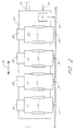
- Figure 2 One embodiment of such a printer is illustrated in Figure 2.
- a print carriage according to one embodiment of the invention comprises a frame 24 which is suspended over the surface of a piece of media 26 on one or more guide rods 28.
- the carriage frame 24 moves back and forth over the media 26 in the direction of arrow 30. Between carriage passes, the media 26 is advanced in the perpendicular direction into or out of the plane of the Figure.
- ink jet cartridges 34 which may be affixed to the carriage with snap-fit tabs 32.
- ink jet cartridges 34 are illustrated. This is common for color ink jet printing, with the cartridges 34 printing cyan, magenta, yellow, and black ink respectively. It will be appreciated that a wide variety of cartridge types and numbers may be provided, and that the invention is applicable to any printing system.
- the ink jet cartridges 34 include jet plates 36 on their bottom surface which selectively deposit ink droplets onto pixel locations on the media 26.
- the jet plates 36 typically comprise one or more columns of ink ejection nozzles which are spaced to define a print resolution in the direction of media travel. In many applications, the jet plates will perform on-demand ink droplet ejection which is actuated thermally or piezoelectrically.
- the carriage also includes an electronic interface for each cartridge 34, which may comprise flex circuits 38 that route electrical signals from the controller 10 ( Figure 1) provided in the printer out to the cartridges 34 for control of the jet plates 36.
- droplets of ink are selectively ejected from each of the jet plates 36 onto desired pixel locations in a strip or swath of parallel raster lines, wherein the strip laid down by each jet plate has a length equal to the length of the jet plate nozzle column.
- these strips may be completely overlapping, partially overlapping, or completely non-overlapping.
- a single pass print mode the media is then be incremented in a direction perpendicular to the direction of carriage travel by an amount equal to the length of the jet plate nozzle columns, and the carriage makes another pass across the media 26, with each jet plate 36 depositing ink droplets at desired pixel locations in the adjacent strip of parallel raster lines.
- two or more nozzles may be used to print onto the pixels of a given raster line over the course of a series of passes by the carriage 24.
- the media may be incremented following each pass by an amount that is less than the length of the jet plate nozzle columns.
- the media 26 may be incremented by 1 ⁇ 4 of the length of the jet plate nozzle column after each pass.
- ink jet printers are well known and conventional, and a wide variety of well known alternative print protocols and printer constructions exist, any of which will be applicable to the present invention.
- the specific construction illustrated herein provides one example of an advantageous application of the invention.
- the carriage frame 24 also provides a mounting location for an optical system 42.
- the optical system 42 receives one or more laser beams 44 from a laser light source.
- the laser light source may be mounted to the printer at a location external to the carriage. This is the embodiment illustrated in Figure 2.
- the laser light source could alternatively be mounted on the carriage frame 24, making the laser light source itself also part of the optical system 42. This may simplify some components of the optical system 42, but currently the size and weight of commercially available laser light sources makes the stationary, printer housing mounted laser generally preferable.
- the optical system 42 may include one or several mirrors to direct the laser light downward toward the media. Beam focusing optics such as lenses may also be provided in the optical system 42.
- the laser light source may comprise a laser diode, a CO 2 laser, or any laser light source with sufficient power to form holes in print media such as paper, vinyl, or textiles.
- the laser light beam(s) 44 and optical system 42 are advantageously configured to selectively apply spots of laser light to a strip of pixel columns as the print carriage 24 passes over the media.
- the optical system 42 may therefore be considered to form a "nozzle plate" which is analogous to the jet plates 36, but which applies laser light to the media rather than ink droplets during the print process.
- the laser light may be used for several purposes.
- the laser may be used to form holes in the media at selected pixel locations.
- the pixel locations which receive bursts of laser light may be selected to join and form a substantially continuous cut boundary having the pre-defined desired shape. This procedure is especially applicable to the essentially simultaneous printing and cutting of garment patterns quickly and with minimal media waste, as is explained further below with reference to Figure 5.
- Beam intensity may be controlled to provide further applications of the invention in addition to those involving actually cutting the media during printing.
- alphanumeric symbols for signs are often manufactured by ink jet printing block letters onto a paper backed vinyl or other plastic substrate. When the symbols are later cut, the cuts are made through the vinyl, but not through the paper backing. When excess vinyl around the symbols is peeled away from the paper backing, some portions of excess vinyl remain, such as in the middle of a letter "0", "A", or number "4", for example. Removing these small and unconnected portions of excess vinyl is referred to as weeding. This separate weeding process may be avoided in some advantageous implementations of the invention.
- one set of holes can be formed through both the vinyl and paper, while another set of holes can be made only through the vinyl, leaving the paper backing underneath substantially intact. In this embodiment, therefore, the weeding process is performed automatically without a separate operation.
- the laser can be used to etch or texture the surface of the media prior to the application of ink to the etched/textured surface.
- beam intensity is selected which ablates the surface of the media, but which does not form a hole through it.
- the desired pattern is first printed onto a paper substrate.
- the textile media will be placed in contact with the printed paper.
- the textile/paper combination is then heated to sublimate the dye and affix the color to the textile.
- the desired pattern can be printed directly onto the desired textile substrate, and an appropriate amount of laser light can be applied to heat the deposited ink. In this example, the heating can be done during the print process, eliminating a separate dye sublimation step.
- the laser light and optical system are configured to direct light onto columns of pixels as the carriage 24 passes over the media.
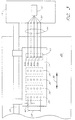
- This configuration is illustrated in the ink jet printer top view of Figure 3.
- the nozzle plates 36 of the cartridges are illustrated without the cartridge body.
- Each nozzle plate comprises a column of five nozzles. Only five nozzles are shown for each jet plate 36 for clarity.
- ink jet printer jet plates will typically include a column of 30-300 or more nozzles.
- nozzle spacing 46 defines print resolution in the vertical direction
- nozzle column length 48 defines the width of the swath deposited by the jet plate during a horizontal pass of the carriage 24 across the media in the direction of arrow 30.
- the optical system 42 which in this embodiment comprises a set of five angled mirrors 50a-50e.
- the mirrors are positioned in a column which is aligned with the nozzle columns 36 also supported on the carriage, with each mirror corresponding to a pixel location in the column of five pixel locations.
- Laser light beams 44 are selectively directed to the mirrors, and are directed downward to the media to heat or cut the media at selected pixel locations.
- the source of laser light may be a laser 52 which is mounted in an end housing 54 of the printer.
- a separate laser may be provided for each mirror.
- an array of laser tubes may be mounted adjacent to one another in the end housing to form a corresponding array of adjacent and parallel output laser beams. These types of parallel laser arrays are used in the packaging industry to mark boxes and other containers. If separate lasers for each pixel in the pixel column are provided, it is possible to apply laser heating to several or all of the pixels of the column simultaneously by firing the desired set of lasers simultaneously.
- a single laser source which has a controllable beam direction so as to apply bursts of laser light to appropriate pixel locations in a serial fashion.
- a method comprises reflecting the laser light off of a rotating polygon. This technique is used in many commercially available bar code scanners.
- Another method, used in some container marking applications comprises reflecting the laser light off of one or more steerable mirrors.
- Yet another approach is to change beam direction acousto-optically. With this type of system, a piezoelectric crystal is used to set up a standing acoustic wave in a refracting medium. Laser light is redirected by refraction off of the standing wave.
- the output of the laser 52 may be directed out at a variety of angles. These beams may be aligned into appropriately spaced parallel beams 44 by prisms, lenses, or other optical elements 58 provided in the housing 54.
- the optics used to alter beam direction such as the rotating polygon, acoustooptic cell, or other device is illustrated in Figure 3 as being incorporated into the laser system 52. It will be appreciated, however, that such beam directing components could alternatively be mounted on the carriage 24.
- the optical system 42 will be moving toward or away from the laser 52 so as to be in a different position over the pixel column for each application of laser light to a selected mirror 50a-50e.
- the optical system 42 may be designed to account for this in a variety of ways, one of which is illustrated in Figure 4.
- the mirrors 50a-50e of the optical system 42 are mounted on the carriage 24 so as to be aligned with vertical pixel columns as shown in the top view of Figure 3.
- five sequential positions of the optical system are shown as the carriage 24 moves rightward in Figure 4 toward the laser 52 in the direction of arrow 30.
- laser beams are directed sequentially to the five mirrors 50a-50e.
- the mirrors may be angled differently to direct the beam downward toward the media 26 in different directions.
- laser light is directed to the top mirror 50a, which is mounted at an angle 62 which is less than 45 degrees from vertical. This directs the laser light slightly forward and ahead of the carriage position, to the center of the pixel column being passed.
- the laser beam is directed to the second mirror 50b. Because the carriage has moved rightward slightly, this mirror 50b is mounted at a larger angle from the vertical such that the laser beam reflected from the second mirror 50b is also directed toward the center of the pixel column being passed.
- the mirrors 50c-50e are mounted at progressively larger angles from vertical such that as the laser light beams are sequentially applied to the mirrors, the light is always directed toward the center of the pixel column. As the carriage continues its pass over the media in the direction of arrow 30, the first mirror 50a becomes properly positioned over the next pixel column 64, an the laser light can be directed toward the first mirror 50a again if this pixel location has been selected to receive laser light.
- the mirrors of the optical system 42 may be mounted at the same angle, but may be staggered horizontally in the direction of carriage motion such that as the carriage passes over a pixel column, the different mirrors are sequentially positioned over its center.
- sequential application of laser light is timed to coincide with the sequential centering of the mirrors over the pixel column.
- the laser dwell time must be less than the amount of time it takes the carriage to move one pixel column divided by the number of mirrors.
- the potential dwell time may be increased by breaking the mirror column up into two or more separated columns and providing a separate laser for addressing each separate mirror column.
- Multi-pass laser cutting modes could also be provided.
- only a defined subset of the mirrors are addressed by the laser with each one of the multiple passes.
- all of the mirrors may be addressed, but at a lower duty cycle than would be the case in a single pass mode.
- any of the wide variety of multi-pass printing techniques currently known and used in ink deposition applications could be applied to the application of laser light to selected raster locations.
- the mirror array is the same length 46 as each ink jet nozzle column. This structure allows cutting to take place during the same carriage passes as are used to perform the printing. It will be appreciated by those of skill in the art, however, that the mirror array need not be aligned with any of the jet plates 36, and could be only partially overlapping, or non-overlapping, in analogy with partially and non-overlapping jet plates well known and used on commercial ink jet printers.
- the array of mirrors should span the entire swath width of all of the jet plates 36. For completely overlapping nozzle plates as shown in Figure 3, this is accomplished by the mirror array of length equal to each nozzle column. For partially or non-overlapping jet plate printer, however, the mirror array would be longer than the individual jet plates so as to be able to apply heat for ink drying to the entire swath width as it is printed. It will also be appreciated that for ink drying applications in bi-directional printing, laser light will need to be available on both sides of the carriage 24. This can be accomplished by including additional beam directing optics on the carriage for routing the light to the other side, or alternatively, a second laser could be mounted in the opposite end housing and operated as described above during carriage motion in the appropriate direction.
- the preferred embodiments of the invention save considerable time and effort when producing cut printed products because the printing and cutting processes are performed at the same time.
- the laser cutting system may be simultaneously illuminating one or a second set of pixels to form holes to cut out the desired shape.
- a printed and cut design may be progressively formed on the media with sequential passes of the ink ejection nozzles and the laser light such that the desired pattern or image is deposited and the cut holes join to produce a substantially continuous cut boundary of the desired shape.
- a printed product with a predefined boundary may thus be produced by cutting along the boundary during the process of ink deposition.
- the cutting process is advantageously rasterized and controlled digitally by the same microprocessor or microcontroller that controls ink ejection during the print process.
- many signs are made by printing a color or pattern onto paper backed vinyl sheets and then cutting out letters from the printed sheets and placing them onto a substrate of a different color or pattern.
- the laser may be focused to cut through the vinyl but not the paper backing, and the sign letters can be cut as they are printed, eliminating the need for a separate vinyl cutting operation.
- garment prototyping can be made significantly more efficient.
- garment prototyping involves printing one or several rolls of material with the desired pattern. Appropriately shaped pieces called for by the garment pattern are then cut from the rolls of printed fabric, and the unused printed fabric is discarded.
- a more efficient process utilizing a combined printer/cutter constructed according to one embodiment of the invention would involve simultaneously printing and cutting only the desired pieces for the garment, rather than cutting them from pre-printed fabric.
- a designer may use conventional design software to nest appropriate garment pieces 66, 68 called for by the garment pattern onto a blank sheet 70. This nesting process may take into account the direction of the fabric weave. The designer may orient the print inside the nested garment pieces 66, 68 in any configuration desired.
- a striped pattern is illustrated which is oriented vertically within one piece 66, and oriented horizontally within another piece 68.
- the designed sheet of fabric 70 is then printed by ink droplet deposition, and the pieces 66, 68 are simultaneously cut out of the sheet 70 with the laser cutter. With this method, no ink is wasted on the parts of the fabric which are going to be discarded. In addition, the pattern is ready for sewing much more quickly than possible with conventional preparation methods.
Landscapes
- Engineering & Computer Science (AREA)
- Physics & Mathematics (AREA)
- Optics & Photonics (AREA)
- Mechanical Engineering (AREA)
- Plasma & Fusion (AREA)
- Forests & Forestry (AREA)
- Life Sciences & Earth Sciences (AREA)
- Health & Medical Sciences (AREA)
- General Health & Medical Sciences (AREA)
- Toxicology (AREA)
- Ink Jet (AREA)
- Handling Of Sheets (AREA)
- Laser Beam Printer (AREA)
- Paper (AREA)
- Ink Jet Recording Methods And Recording Media Thereof (AREA)
Priority Applications (1)
| Application Number | Priority Date | Filing Date | Title |
|---|---|---|---|
| EP04005788A EP1428671A1 (en) | 1999-11-08 | 2000-11-08 | Digital media cutter |
Applications Claiming Priority (3)
| Application Number | Priority Date | Filing Date | Title |
|---|---|---|---|
| US43687799A | 1999-11-08 | 1999-11-08 | |
| US436877 | 1999-11-09 | ||
| PCT/US2000/042070 WO2001038097A2 (en) | 1999-11-08 | 2000-11-08 | Digital media cutter |
Related Child Applications (1)
| Application Number | Title | Priority Date | Filing Date |
|---|---|---|---|
| EP04005788A Division EP1428671A1 (en) | 1999-11-08 | 2000-11-08 | Digital media cutter |
Publications (2)
| Publication Number | Publication Date |
|---|---|
| EP1227936A2 EP1227936A2 (en) | 2002-08-07 |
| EP1227936B1 true EP1227936B1 (en) | 2005-03-09 |
Family
ID=23734187
Family Applications (2)
| Application Number | Title | Priority Date | Filing Date |
|---|---|---|---|
| EP00992333A Expired - Lifetime EP1227936B1 (en) | 1999-11-08 | 2000-11-08 | Digital media cutter |
| EP04005788A Withdrawn EP1428671A1 (en) | 1999-11-08 | 2000-11-08 | Digital media cutter |
Family Applications After (1)
| Application Number | Title | Priority Date | Filing Date |
|---|---|---|---|
| EP04005788A Withdrawn EP1428671A1 (en) | 1999-11-08 | 2000-11-08 | Digital media cutter |
Country Status (5)
| Country | Link |
|---|---|
| EP (2) | EP1227936B1 (ja) |
| JP (1) | JP4869528B2 (ja) |
| AU (1) | AU4304201A (ja) |
| DE (1) | DE60018593T2 (ja) |
| WO (1) | WO2001038097A2 (ja) |
Families Citing this family (5)
| Publication number | Priority date | Publication date | Assignee | Title |
|---|---|---|---|---|
| SE0203251D0 (sv) * | 2002-11-06 | 2002-11-06 | Designe Force Ab | Metod att åstadkomma grafiskt samt tvådimensionellt formgivna stycken |
| IL164679A0 (en) | 2004-10-19 | 2005-12-18 | Rafi Bronstein Scitex Vision L | A method of inkjet printing with image quality control |
| CA2730619A1 (en) * | 2008-07-16 | 2010-01-21 | Provo Craft And Novelty, Inc. | System and method for printing and cutting |
| JP5786456B2 (ja) * | 2011-05-24 | 2015-09-30 | セイコーエプソン株式会社 | 液体吐出装置、及び、液体吐出方法 |
| CN107438495B (zh) | 2015-02-12 | 2021-02-05 | 格罗弗治公司 | 云控制激光制造 |
Family Cites Families (3)
| Publication number | Priority date | Publication date | Assignee | Title |
|---|---|---|---|---|
| EP0385417B1 (en) | 1989-02-28 | 1994-06-01 | Canon Kabushiki Kaisha | An ink jet recording apparatus |
| IL106952A (en) | 1993-09-08 | 1996-03-31 | Scitex Corp Ltd | Laser marker |
| US6173211B1 (en) | 1998-04-15 | 2001-01-09 | Gerber Technology, Inc. | Apparatus and method for fabric printing of nested |
-
2000
- 2000-11-08 WO PCT/US2000/042070 patent/WO2001038097A2/en active IP Right Grant
- 2000-11-08 DE DE60018593T patent/DE60018593T2/de not_active Expired - Lifetime
- 2000-11-08 JP JP2001539683A patent/JP4869528B2/ja not_active Expired - Fee Related
- 2000-11-08 AU AU43042/01A patent/AU4304201A/en not_active Abandoned
- 2000-11-08 EP EP00992333A patent/EP1227936B1/en not_active Expired - Lifetime
- 2000-11-08 EP EP04005788A patent/EP1428671A1/en not_active Withdrawn
Also Published As
| Publication number | Publication date |
|---|---|
| WO2001038097A3 (en) | 2002-05-02 |
| DE60018593T2 (de) | 2006-03-09 |
| JP4869528B2 (ja) | 2012-02-08 |
| EP1428671A1 (en) | 2004-06-16 |
| WO2001038097A2 (en) | 2001-05-31 |
| AU4304201A (en) | 2001-06-04 |
| JP2003535713A (ja) | 2003-12-02 |
| DE60018593D1 (de) | 2005-04-14 |
| EP1227936A2 (en) | 2002-08-07 |
Similar Documents
| Publication | Publication Date | Title |
|---|---|---|
| US6491361B1 (en) | Digital media cutter | |
| US6464316B1 (en) | Bi-directional printmode for improved edge quality | |
| KR930002722B1 (ko) | 2중 모드 잉크 젯트 인쇄기 | |
| JP3231786B2 (ja) | 高解像度マトリクスインクジェット装置 | |
| EP0748693B1 (en) | Thermal ink jet printhead with extended print capability | |
| EP0595657B1 (en) | Ink jet recording method and ink jet recording apparatus | |
| KR970005635A (ko) | 컬러 필터 제조방법 및 장치, 잉크 젯 장치, 컬러 필터, 표시장치, 및 표시 장치를 가진 장치 | |
| KR970005634A (ko) | 컬러 필터 제조방법과 제조장치 및 컬러 필터, 컬러 필터 기판, 디스플레이 디바이스와 디스플레이 디바이스를 구지한 장치 | |
| JPH08258289A (ja) | 印刷方法 | |
| JPH06344557A (ja) | ドットプリンタ用インクジェット式印刷ヘッド | |
| EP1176021B1 (en) | Printing system that utilizes print masks with resolutions that are non-integral multiples of each other | |
| KR960010246A (ko) | 칼라 필터, 칼라 필터를 사용하는 디스플레이 디바이스, 디스플레이 디바이스 및 잉크 젯 헤드를 포함하는 장치, 및 칼라 필터 제조 방법 및 장치 | |
| KR970062762A (ko) | 칼라 필터 제조 방법 및 장치, 칼라 필터, 디스플레이 장치, 및 디스플레이 장치를 구비한 장치. | |
| RU2096183C1 (ru) | Способ струйной печати и струйная печатающая головка для его осуществления | |
| KR100379148B1 (ko) | 프린트이미지생성방법및프린팅시스템 | |
| JP2002166578A (ja) | インクジェット記録方法およびインクジェット記録装置 | |
| EP1227936B1 (en) | Digital media cutter | |
| JPH1086353A (ja) | インクジェット記録装置 | |
| JPH08174805A (ja) | インクジェットプリンタ | |
| US6854829B2 (en) | Laser-actuatable inkjet printing system and printer | |
| JP2003535713A6 (ja) | デジタルメディアカッタ | |
| JPH07285218A (ja) | インクジェット記録方法、記録装置および情報処理システム | |
| JPH1134360A (ja) | インクジェットプリンタ | |
| US20170232728A1 (en) | Cutting assembly for a multi-roll printer | |
| JPH0858083A (ja) | インクジェットプリント方法およびその装置 |
Legal Events
| Date | Code | Title | Description |
|---|---|---|---|
| PUAI | Public reference made under article 153(3) epc to a published international application that has entered the european phase |
Free format text: ORIGINAL CODE: 0009012 |
|
| 17P | Request for examination filed |
Effective date: 20020422 |
|
| AK | Designated contracting states |
Kind code of ref document: A2 Designated state(s): AT BE CH CY DE DK ES FI FR GB GR IE IT LI LU MC NL PT SE TR |
|
| AX | Request for extension of the european patent |
Free format text: AL;LT;LV;MK;RO;SI |
|
| 17Q | First examination report despatched |
Effective date: 20030306 |
|
| GRAP | Despatch of communication of intention to grant a patent |
Free format text: ORIGINAL CODE: EPIDOSNIGR1 |
|
| GRAS | Grant fee paid |
Free format text: ORIGINAL CODE: EPIDOSNIGR3 |
|
| RBV | Designated contracting states (corrected) |
Designated state(s): DE FR GB |
|
| GRAA | (expected) grant |
Free format text: ORIGINAL CODE: 0009210 |
|
| AK | Designated contracting states |
Kind code of ref document: B1 Designated state(s): DE FR GB |
|
| REG | Reference to a national code |
Ref country code: GB Ref legal event code: FG4D |
|
| REG | Reference to a national code |
Ref country code: IE Ref legal event code: FG4D |
|
| REF | Corresponds to: |
Ref document number: 60018593 Country of ref document: DE Date of ref document: 20050414 Kind code of ref document: P |
|
| PLBE | No opposition filed within time limit |
Free format text: ORIGINAL CODE: 0009261 |
|
| STAA | Information on the status of an ep patent application or granted ep patent |
Free format text: STATUS: NO OPPOSITION FILED WITHIN TIME LIMIT |
|
| ET | Fr: translation filed | ||
| 26N | No opposition filed |
Effective date: 20051212 |
|
| REG | Reference to a national code |
Ref country code: GB Ref legal event code: 732E |
|
| PGFP | Annual fee paid to national office [announced via postgrant information from national office to epo] |
Ref country code: GB Payment date: 20101022 Year of fee payment: 11 |
|
| PGFP | Annual fee paid to national office [announced via postgrant information from national office to epo] |
Ref country code: FR Payment date: 20111103 Year of fee payment: 12 |
|
| PGFP | Annual fee paid to national office [announced via postgrant information from national office to epo] |
Ref country code: DE Payment date: 20111130 Year of fee payment: 12 |
|
| GBPC | Gb: european patent ceased through non-payment of renewal fee |
Effective date: 20121108 |
|
| REG | Reference to a national code |
Ref country code: FR Ref legal event code: ST Effective date: 20130731 |
|
| REG | Reference to a national code |
Ref country code: DE Ref legal event code: R119 Ref document number: 60018593 Country of ref document: DE Effective date: 20130601 |
|
| PG25 | Lapsed in a contracting state [announced via postgrant information from national office to epo] |
Ref country code: DE Free format text: LAPSE BECAUSE OF NON-PAYMENT OF DUE FEES Effective date: 20130601 |
|
| PG25 | Lapsed in a contracting state [announced via postgrant information from national office to epo] |
Ref country code: FR Free format text: LAPSE BECAUSE OF NON-PAYMENT OF DUE FEES Effective date: 20121130 Ref country code: GB Free format text: LAPSE BECAUSE OF NON-PAYMENT OF DUE FEES Effective date: 20121108 |