EP1227355B1 - Microscope for wide angle inspection, especially for eye operations - Google Patents
Microscope for wide angle inspection, especially for eye operations Download PDFInfo
- Publication number
- EP1227355B1 EP1227355B1 EP01121232A EP01121232A EP1227355B1 EP 1227355 B1 EP1227355 B1 EP 1227355B1 EP 01121232 A EP01121232 A EP 01121232A EP 01121232 A EP01121232 A EP 01121232A EP 1227355 B1 EP1227355 B1 EP 1227355B1
- Authority
- EP
- European Patent Office
- Prior art keywords
- microscope
- beam path
- microscope according
- lens
- eye
- Prior art date
- Legal status (The legal status is an assumption and is not a legal conclusion. Google has not performed a legal analysis and makes no representation as to the accuracy of the status listed.)
- Expired - Lifetime
Links
Images


Classifications
-
- A—HUMAN NECESSITIES
- A61—MEDICAL OR VETERINARY SCIENCE; HYGIENE
- A61B—DIAGNOSIS; SURGERY; IDENTIFICATION
- A61B3/00—Apparatus for testing the eyes; Instruments for examining the eyes
- A61B3/10—Objective types, i.e. instruments for examining the eyes independent of the patients' perceptions or reactions
- A61B3/13—Ophthalmic microscopes
-
- G—PHYSICS
- G02—OPTICS
- G02B—OPTICAL ELEMENTS, SYSTEMS OR APPARATUS
- G02B17/00—Systems with reflecting surfaces, with or without refracting elements
- G02B17/02—Catoptric systems, e.g. image erecting and reversing system
- G02B17/04—Catoptric systems, e.g. image erecting and reversing system using prisms only
-
- G—PHYSICS
- G02—OPTICS
- G02B—OPTICAL ELEMENTS, SYSTEMS OR APPARATUS
- G02B21/00—Microscopes
- G02B21/0004—Microscopes specially adapted for specific applications
- G02B21/0012—Surgical microscopes
-
- A—HUMAN NECESSITIES
- A61—MEDICAL OR VETERINARY SCIENCE; HYGIENE
- A61B—DIAGNOSIS; SURGERY; IDENTIFICATION
- A61B3/00—Apparatus for testing the eyes; Instruments for examining the eyes
- A61B3/10—Objective types, i.e. instruments for examining the eyes independent of the patients' perceptions or reactions
- A61B3/12—Objective types, i.e. instruments for examining the eyes independent of the patients' perceptions or reactions for looking at the eye fundus, e.g. ophthalmoscopes
- A61B3/125—Objective types, i.e. instruments for examining the eyes independent of the patients' perceptions or reactions for looking at the eye fundus, e.g. ophthalmoscopes with contact lenses
Definitions
- the invention relates to a microscope for wide-angle viewing of an eye with a located between the lens and the eye to be treated, designed a reversed image optics for observation of the ocular fundus, especially for eye surgery, and with a in the beam path of the microscope located, preferably einschieb- or einschwenkbaren device for image inversion and erection.
- the invention has therefore set itself the task of designing a microscope of the type described in more detail so that its height does not have to be significantly increased even if it can be optionally operated with a device for image inversion and erection.
- a microscope according to claim 1 is provided.
- the arrangement according to the invention makes use of the space present between the objective and the eye to be treated, so that overall the overall height of the microscope is maintained even when a laterally correct and upright image is generated in the eyepiece. It plays It does not matter in which way the wide-angle viewing is produced: the optics for observation of the fundus can be attached both to the holder for the prism system and to be placed directly on the eye. In this way, immediately after swiveling or inserting the device a right-angled and upright image that does not have to be prepared by a further operation that eliminates the otherwise required hand or foot operation, which is just an eye surgery of great advantage.
- the image reversion and alignment device can be inserted into the area between the lens and the eye. But it is much easier if the holder around one at the bottom of
- Microscope is rotatable at this arranged pivot axis, so that only a few components are required to swing the device from a stand-by position in the beam path of the microscope.
- the prism system is best arranged in a closed housing, which is provided with openings for the beam path. Between the prism system and the lens can still be provided after insertion or pivoting of the prismatic system in the beam path of the microscope directly adjacent to the lens imaging optics for adjusting the beam path, preferably in the lens adjacent opening of the housing.
- the pivot axis for the holder is provided approximately horizontally on the microscope.
- the optics for (wide-angle) observation of the fundus may consist of a lens system movably arranged along the beam path.
- the distance of this lens system to the eye can be left unchanged during the work of the surgeon, because for focusing in the beam path between the optics for observation of the fundus and the prism system is provided along the beam path and movable relative to the prism system optics;
- a single optical lens which in turn can be focused, is sufficient.
- both optics for wide-angle observation and / or for adaptation of the intermediate image can be actuated by hand or electric motor-driven spindle drives.
- the optics for observing the ocular fundus can be moved along the beam path by means of a first spindle drive attached to the holder, most simply in such a way that the optic is mounted on a crossmember which is mounted on a holder attached to the holder and to the first spindle drive extending parallel guide pin is longitudinally movably guided, wherein on the guide pin, a first knob is mounted for the first spindle drive.
- the entire adjustment mechanism for the optics is connected in this way with the holder and thus also with the prism system and always remains precisely adjusted.
- the optical system for adjusting the intermediate observation can be moved when it is movable along the beam path by means of a second spindle drive attached to the guide pin, with a second rotary knob serving for this purpose.
- the prism system can, for example, be designed as a reflection prism according to Uppendahl or Schmidtpechan.
- the knobs for the spindle drives can be actuated by hand; but advantageously they are actuated by means of an electric drive, wherein such a drive, for example, has a preferably located on the holder electric motor, the output via a flexible shaft with the rotary knob is rotatably coupled, so that the circuit may be made by a foot-operated switch so that the surgeon keeps his hands free when refocused.
- the arrangement of the device for image inversion and - erection is therefore quite universally applicable to microscopes of very different design; Existing microscopes can be retrofitted without much effort and thus better adapted to the requirements during surgical treatment.
- the device can also be very quickly removed from the beam path of the microscope, without the surgeon interrupting his work on the eye of a patient or an auxiliary power would have to be consulted.
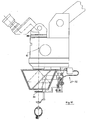
- an eyepiece 1 which is pivotable about an axis 2, so that, for example in an eye operation, the surgeon can optimally adjust the eyepiece 1 of his posture during surgery. Furthermore, an adjustment 3 for changing the magnification scale is provided on the microscope.
- An objective 4 initially allows observation of the front portion of the eye 5 on an eye 6.
- an optical system 8 for observation of the fundus 9 is supported, which can be pivoted into the beam path 10 of the microscope and by means of a (first) Spindle drive 11 in the direction of the beam path 10 is movable.
- This optics 8 here a simple observation lens, is attached to a holder 12, which is pivotable about a swivel pin 13 fixed to the projection 7.
- the optics 8 is attached to a (first) traverse 14, which is guided on a guide pin 15 parallel to the beam path 10 below the lens 4 movable.
- the cross member 14 is moved by a driver, not shown, which engages in the threaded spindle 17.
- the guide pin 15 and the threaded spindle 17 are on the one hand in a common, locked to the holder 12 bearing piece 18 and on the other hand in a (first) connecting plate 19 attached.
- the threaded spindle 17 is rotatably mounted about its axis.
- a (first) knob 20 is provided, with the aid of the spindle output 11 can be set in motion and the optics 8 along the beam path 10 is movable.
- the optics 8 is attached to the retaining bolt 22, which is resiliently held in a guide 21.
- the complete spindle drive is separable from the holder 12 on the bearing piece 18 so that it can be sterilized.
- An image reversion and alignment device 23 connected to the optic 8 through the common holder 12 consists of a porro prism system 2 of the type 24 and a housing 25 accommodating the prism system 24; the housing 25 may be formed integrally with the holder 12 and the bearing piece 18.
- the bearing piece 18 is detachably formed by the holder 12.
- the prism system 24 Depending on an opening 26,27 in the housing 25 allow the passage of the beam path 10 through the prism system 24.
- the input of the beam path 10 in the prism system 24 is connected in the lens 4 adjacent opening 26 an imaging optics 28 for adjusting the due to the prism system 24th considerably extended beam path 10.
- the spindle drive 11 is equipped with an electric motor drive.
- an electric motor 29 is provided on the projection 7, from the output of a connectable by means of a suitable coupling 30 flexible shaft 31 and a belt drive 32, the threaded spindle 17 can be rotated.
- the electric motor can also be mounted elsewhere in the system. It is therefore sufficient to switch the electric motor 29 from a foot switch to move the optics 8 along the beam path 10; For example, a surgeon can focus accordingly, without putting his surgical instruments out of his hands and thus having to interrupt the ongoing operation.
- One way to focus the optics 8, without having to move at all, according to the invention provides a longitudinally along the beam path 10 movable optics 34 for adapting the intermediate image accordingly Fig.7-10 ,
- a (second) spindle drive 35 is installed for the optics 34, in this case a simple lens, one each further guide pin 36 and one threaded spindle 37 on the side remote from the first spindle drive 11 attached to the first connecting plate 19 and held together at its other end by a (second) connecting strap 38.
- the optic 34 is supported in a (second) cross member 39, which is just like the first cross member 14 contains a driver, which is moved by the rotating threaded spindle 37 in the direction of the beam path 10 when a corresponding, on the threaded spindle 37 held (second) knob 40 is actuated ( Figure 7 . 8th ).
- the spindle drive 35 but also according Figure 9 . 10 in a similar manner as the spindle drive 11 means of the electric drive 29-32 are operated.
- Fig. 14 shows the beam path below the microscope, this beam path through the use of four prisms, like them Fig. 15 . 16 show, has been improved. In particular, this results in an enlargement of the stereoscopic basis, which also eliminates aberrations. The advantage of this arrangement is that shading can not occur, thus ensuring better stereoscopic vision.
- the prisms used are equally strong, wherein the base of the underlying prisms 40 and 41 is trimmed to each other, while the closest to the lens 4 prisms 42 and 43 have their base directed outward. The drawn with the arrow B stereoscopic width is thereby significantly improved.
- the prisms have, for example, with a lens focal length of 200 mm, advantageously 5 pdpt (prismendioptrin).
- the same prisms 40 to 43 are arranged below or above the prism system 24, wherein in each case a converging lens 44, 45 or a diverging lens 46 or 47 are respectively arranged between the prisms 40, 41 and 42, 43.
- a converging lens 44, 45 or a diverging lens 46 or 47 are respectively arranged between the prisms 40, 41 and 42, 43.
Description
Die Erfindung betrifft ein Mikroskop zur Weitwinkel-Betrachtung eines Auges mit einer zwischen dem Objektiv und dem zu behandelnden Auge befindlichen, ein seitenverkehrtes Bild entwerfenden Optik zur Beobachtung des Augenhintergrundes, insbesondere für Augenoperationen, und mit einer in den Strahlengang des Mikroskops gelegenen, vorzugsweise einschieb- bzw. einschwenkbaren Einrichtung zur Bildumkehrung und -aufrichtung.The invention relates to a microscope for wide-angle viewing of an eye with a located between the lens and the eye to be treated, designed a reversed image optics for observation of the ocular fundus, especially for eye surgery, and with a in the beam path of the microscope located, preferably einschieb- or einschwenkbaren device for image inversion and erection.
Man kann eine Weitwinkel-Beobachtung des Auges in einfacher Weise durch eine dem Auge unmittelbar aufgesetzte Kontaktlinse vornehmen. Stattdessen ist es auch möglich, dass eine gesonderte, von dem Auge beabstandete Optik an dem Mikroskop angebracht ist. Werden dafür asphärische Linsen verwendet, die allein eine ausreichende Weitwinkel-Betrachtung gewährleisten, dann wird genauso wie mit der Kontaktlinse im Mikroskop ein seitenverkehrtes, kopfstehendes Bild erzeugt, welches bei der Diagnostik hingenommen werden kann; bei Augenoperationen, die vorteilhaft mindestens zeitweise ebenfalls bei Weitwinkel-Betrachtung unter Stereobeobachtung durchgeführt werden müssen, kommt eine umgekehrte Stereopsis hinzu, so dass selbst geübten Operateuren eine derartige Kontrolltechnik nicht zugemutet werden kann.It is possible to make a wide-angle observation of the eye in a simple manner by a contact lens placed directly on the eye. Instead, it is also possible that a separate, spaced from the eye optics is attached to the microscope. If aspherical lenses are used for this purpose, which alone ensure a sufficient wide-angle view, then the same way as with the contact lens in the microscope, a reversed, inverted image is generated, which can be tolerated in the diagnosis; in ophthalmic surgery, which advantageously at least temporarily also carried out under wide-angle viewing under stereo observation must be added, a reverse stereopsis is added so that even experienced surgeons such a control technique can not be expected.
Es ist auch schon bekannt, bei einem derartigen Mikroskop eine Einrichtung zur Bildumkehrung und -aufrichtung vorzusehen, wie das in der
Die Erfindung hat sich deshalb die Aufgabe gestellt, ein Mikroskop der eingangs näher bezeichneten Art so auszubilden, dass seine Bauhöhe auch dann nicht wesentlich vergrößert werden muß, wenn es wahlweise mit einer Einrichtung zur Bildumkehrung und -aufrichtung betrieben werden kann.The invention has therefore set itself the task of designing a microscope of the type described in more detail so that its height does not have to be significantly increased even if it can be optionally operated with a device for image inversion and erection.
Erfindungsgemäß wird ein Mikroskop gemäß Anspruch 1 bereitgestellt. Die erfindungsgemäße Anordnung macht sich den zwischen dem Objektiv und dem zu behandelnden Auge vorhandenen Raum zunutze, so dass insgesamt die Bauhöhe des Mikroskops auch dann erhalten bleibt, wenn in dem Okular ein seitenrichtiges und aufrechtstehendes Bild erzeugt wird. Dabei spielt es keine Rolle, in welcher Weise die Weitwinkel-Betrachtung produziert wird: die Optik zur Beobachtung des Augenhintergrundes kann sowohl an dem Halter für das Prismensystem angebracht als auch unmittelbar auf das Auge aufsetzbar ausgebildet sein. Auf diese Weise entsteht sofort nach dem Einschwenken bzw. Einschieben der Einrichtung ein seitenrichtiges und aufrechtstehendes Bild, das nicht erst durch eine weitere Betätigung hergestellt werden muß, die dazu sonst erforderliche Hand- oder Fußbetätigung entfällt, was gerade bei einer Augenoperation von großem Vorteil ist.According to the invention, a microscope according to claim 1 is provided. The arrangement according to the invention makes use of the space present between the objective and the eye to be treated, so that overall the overall height of the microscope is maintained even when a laterally correct and upright image is generated in the eyepiece. It plays It does not matter in which way the wide-angle viewing is produced: the optics for observation of the fundus can be attached both to the holder for the prism system and to be placed directly on the eye. In this way, immediately after swiveling or inserting the device a right-angled and upright image that does not have to be prepared by a further operation that eliminates the otherwise required hand or foot operation, which is just an eye surgery of great advantage.
Die Einrichtung zur Bildumkehrung und -aufrichtung kann in den Bereich zwischen dem Objektiv und dem Auge eingeschoben werden. Wesentlich einfacher ist es aber, wenn der Halter um eine an der Unterseite desThe image reversion and alignment device can be inserted into the area between the lens and the eye. But it is much easier if the holder around one at the bottom of
Mikroskops an diesem angeordnete Schwenkachse drehbar ist, so dass nur wenige Bauteile erforderlich sind, um die Einrichtung aus einer Betriebsbereitschafts-Stellung in den Strahlengang des Mikroskops einzuschwenken. Das Prismensystem ist dabei am besten in einem geschlossenen Gehäuse angeordnet, das mit Durchbrechungen für den Strahlengang versehen ist. Zwischen dem Prismensystem und dem Objektiv kann noch eine nach dem Einschieben bzw. Einschwenken des Prismensystems in den Strahlengang des Mikroskops dem Objektiv unmittelbar benachbarte Abbildungsoptik zur Anpassung des Strahlenganges vorgesehen sein, am besten in der dem Objektiv benachbarten Durchbrechung des Gehäuses. Im übrigen ist es zweckmäßig, wenn die Schwenkachse für den Halter etwa waagerecht an dem Mikroskop vorgesehen ist.Microscope is rotatable at this arranged pivot axis, so that only a few components are required to swing the device from a stand-by position in the beam path of the microscope. The prism system is best arranged in a closed housing, which is provided with openings for the beam path. Between the prism system and the lens can still be provided after insertion or pivoting of the prismatic system in the beam path of the microscope directly adjacent to the lens imaging optics for adjusting the beam path, preferably in the lens adjacent opening of the housing. Moreover, it is expedient if the pivot axis for the holder is provided approximately horizontally on the microscope.
Die Optik zur (Weitwinkel-) Beobachtung des Augenhintergrundes kann aus einem längs des Strahlenganges beweglich angeordneten Linsensystem bestehen. Der Abstand dieses Linsensystems zu dem Auge kann während der Arbeit des Operateurs von diesem unverändert belassen werden, weil zum Fokussieren in dem Strahlengang zwischen der Optik zur Beobachtung des Augenhintergrundes und dem Prismensystem eine längs des Strahlenganges und relativ zu dem Prismensystem bewegliche Optik vorgesehen ist; dazu genügt bereits eine einzelne optische Linse, die ihrerseits fokussierbar ist.The optics for (wide-angle) observation of the fundus may consist of a lens system movably arranged along the beam path. The distance of this lens system to the eye can be left unchanged during the work of the surgeon, because for focusing in the beam path between the optics for observation of the fundus and the prism system is provided along the beam path and movable relative to the prism system optics; For this purpose, a single optical lens, which in turn can be focused, is sufficient.
Es ist vorteilhaft, wenn zum Fokussieren beide Optiken zur Weitwinkel-Beobachtung und/oder zur Anpassung der Zwischenabbildung mittels handoder elektromotorisch angetriebener Spindeltriebe betätigbar sind. So kann etwa die Optik zur Beobachtung des Augenhintergrundes mittels eines an dem Halter befestigten ersten Spindeltriebes längs des Strahlenganges bewegbar sein, am einfachsten in der Weise, dass die Optik an einer Traverse gehaltert ist, welche auf einem an dem Halter angebrachten und zu dem ersten Spindeltrieb sich parallel erstreckenden Führungsstift längsbeweglich geführt ist, wobei an dem Führungsstift ein erster Drehknopf für den ersten Spindeltrieb gelagert ist. Die gesamte Verstell-Mechanik für die Optik ist auf diese Weise mit dem Halter und damit auch mit dem Prismensystem verbunden und bleibt stets genau justiert.It is advantageous if, for focusing purposes, both optics for wide-angle observation and / or for adaptation of the intermediate image can be actuated by hand or electric motor-driven spindle drives. Thus, for example, the optics for observing the ocular fundus can be moved along the beam path by means of a first spindle drive attached to the holder, most simply in such a way that the optic is mounted on a crossmember which is mounted on a holder attached to the holder and to the first spindle drive extending parallel guide pin is longitudinally movably guided, wherein on the guide pin, a first knob is mounted for the first spindle drive. The entire adjustment mechanism for the optics is connected in this way with the holder and thus also with the prism system and always remains precisely adjusted.
In ähnlicher Weise kann mit der Optik zur Anpassung der Zwischenbeobachtung verfahren werden, wenn diese mittels eines an dem Führungsstift befestigten zweiten Spindeltriebes längs des Strahlenganges bewegbar ist, wobei hierzu ein zweiter Drehknopf dient.Similarly, the optical system for adjusting the intermediate observation can be moved when it is movable along the beam path by means of a second spindle drive attached to the guide pin, with a second rotary knob serving for this purpose.
Das Prismensystem kann, beispielsweise, als Reflexionsprisma nach Uppendahl oder Schmidtpechan ausgebildet sein.The prism system can, for example, be designed as a reflection prism according to Uppendahl or Schmidtpechan.
Die Drehknöpfe für die Spindeltriebe können von Hand betätigbar sein; in vorteilhafter Weise sind sie aber mittels eines elektrischen Antriebes betätigbar, wobei ein solcher Antrieb beispielsweise einen vorzugsweise an dem Halter befindlichen Elektromotor aufweist, dessen Abtrieb über eine biegsame Welle mit dem Drehknopf rotatorisch koppelbar ist, so dass die Schaltung gegebenenfalls durch einen fußbetätigten Schalter vorgenommen werden, so dass der Operateur seine Hände frei behält, wenn nachfokussiert werden muß.The knobs for the spindle drives can be actuated by hand; but advantageously they are actuated by means of an electric drive, wherein such a drive, for example, has a preferably located on the holder electric motor, the output via a flexible shaft with the rotary knob is rotatably coupled, so that the circuit may be made by a foot-operated switch so that the surgeon keeps his hands free when refocused.
Die Anordnung der Einrichtung zur Bildumkehrung und - aufrichtung ist deshalb recht universell an Mikroskopen ganz unterschiedlicher Bauart einsetzbar; vorhandene Mikroskope können ohne viel Aufwand entsprechend nachgerüstet und damit den Anforderungen während der operativen Versorgung besser angepaßt werden. Die Einrichtung kann aber auch sehr schnell aus dem Strahlengang des Mikroskops wieder entfernt werden, ohne dass der Operateur seine Arbeit am Auge eines Patienten unterbrechen oder dazu eine Hilfskraft hinzugezogen werden müßte.The arrangement of the device for image inversion and - erection is therefore quite universally applicable to microscopes of very different design; Existing microscopes can be retrofitted without much effort and thus better adapted to the requirements during surgical treatment. The device can also be very quickly removed from the beam path of the microscope, without the surgeon interrupting his work on the eye of a patient or an auxiliary power would have to be consulted.
Die Erfindung wird nachstehend an Hand der Zeichnung an einem Ausführungsbeispiel noch weiter erläutert. Es zeigen
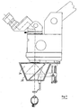
- Fig. 1
- ein Mikroskop mit einer Optik zur Weitwinkel-Beobachtung und einem Prismensystem nach Uppendahl in der Seitenansicht, das nicht in den Schutzumfang von Anspruch 1 fällt.
- Fig. 2
- ein Mikroskop entsprechend
Fig. 1 , jedoch mit einem Prismensystem nach Schmidtpechan, - Fig. 3
- bzw.
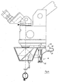
Fig. 4 ein Mikroskop entsprechendFig. 1 bzw.Fig. 2 mit jeweils einem elektrischen Antrieb für die Optik zur Weitwinkel-Beobachtung, - Fig. 5
- ein Mikroskop entsprechend
Fig. 1 mit einer gegenüberFig. 3 veränderten Optik zur Weitwinkel-Beobachtung, - Fig. 6
- ein Mikroskop entsprechend
Fig. 2 mit einer gegenüberFig. 4 veränderten Optik zur Weitwinkel-Beobachtung, - Fig. 7
- bzw.
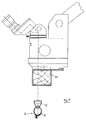
Fig. 8 ein Mikroskop entsprechendFig. 1 bzw.Fig. 2 mit einer von Hand antreibbaren Optik zur Anpassung der Zwischenabbildung, gemäß einer Ausführungsform der Erfindung, - Fig. 9
- bzw. 10. ein Mikroskop entsprechend
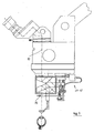
Fig. 7 bzw.Fig. 8 mit einer elektrisch antreibbaren Optik zur Anpassung der Zwischenabbildung, gemäß einer Ausführungsform der Erfindung, - Fig. 11
- ein Mikroskop entsprechend den
Fig. 1 bis 5 , mit einemPorroprisma 2. Art, - Fig. 12
- ein Mikroskop entsprechend
Fig. 6 , jedoch mit einemPorroprisma 2. Art, - Fig. 13
- ein Mikroskop entsprechend
Fig. 10 , jedoch mit einemPorroprisma 2. Art, - Fig. 14
- den Strahlengang in einem Mikroskop, entsprechend den
Fig. 1 bis 13 , - Fig. 15
- den gleichen Strahlengang wie in
Fig. 14 , jedoch unter Verwendung von vier weiteren Prismensystemen und - Fig. 16
- den gleichen Strahlengang wie in
Fig. 15 , jedoch unter Verwendung zusätzlicher Zerstreuungs- und Sammellinsen,
- Fig. 1
- a microscope with a lens for wide-angle observation and a prism system Uppendahl in the side view, which does not fall within the scope of claim 1.
- Fig. 2
- a microscope accordingly
Fig. 1 , but with a prism system according to Schmidtpechan, - Fig. 3
- respectively.
Fig. 4 a microscope accordinglyFig. 1 respectively.Fig. 2 each with an electric drive for the optics for wide-angle observation, - Fig. 5
- a microscope accordingly
Fig. 1 with one oppositeFig. 3 changed optics for wide-angle observation, - Fig. 6
- a microscope accordingly
Fig. 2 with one oppositeFig. 4 changed optics for wide-angle observation, - Fig. 7
- respectively.
Fig. 8 a microscope accordinglyFig. 1 respectively.Fig. 2 with a hand-drivable optical system for adapting the intermediate image, according to an embodiment of the invention, - Fig. 9
- or 10. a microscope accordingly
Fig. 7 respectively.Fig. 8 with an electrically drivable optical system for adapting the intermediate image, according to an embodiment of the invention, - Fig. 11
- a microscope according to the
Fig. 1 to 5 , with a Porro prism of the 2nd kind, - Fig. 12
- a microscope accordingly
Fig. 6 , but with a Porro prism of the 2nd kind, - Fig. 13
- a microscope accordingly
Fig. 10 , but with a Porro prism of the 2nd kind, - Fig. 14
- the beam path in a microscope, according to the
Fig. 1 to 13 . - Fig. 15
- the same beam path as in
Fig. 14 but using four more prism systems and - Fig. 16
- the same beam path as in
Fig. 15 but using additional diverging and converging lenses,
An einem Mikroskop befindet sich zunächst entsprechend
An einem Ansatz 7 des Mikroskops in der Nachbarschaft des Objektivs 4 ist eine Optik 8 zur Beobachtung des Augenhintergrundes 9 gehaltert, die in den Strahlengang 10 des Mikroskops einschwenkbar und mittels eines (ersten) Spindeltrieb 11 in Richtung des Strahlenganges 10 bewegbar ist. Diese Optik 8, hier eine einfache Beobachtungslinse, ist an einem Halter 12 angebracht, welcher um eine an dem Ansatz 7 ortsfeste Schwenkachse 13 schwenkbar ist. Die Optik 8 ist an einer (ersten) Traverse 14 befestigt, die auf einem Führungsstift 15 parallel zu dem Strahlengang 10 unterhalb des Objektivs 4 bewegbar geführt ist. Die Traverse 14 wird durch einen nicht dargestellten Mitnehmer, der in die Gewindespindel 17 eingreift, bewegt. Der Führungsstift 15 und die Gewindespindel 17 sind einerseits in einem gemeinsamen, an dem Halter 12 arretierten Lagerstück 18 und andererseits in einer (ersten) Verbindungslasche 19 befestigt. Die Gewindespindel 17 ist um ihre Achse drehbar gelagert. In Verbindung mit der Gewindespindel 17 ist ein (erster) Drehknopf 20 vorgesehen, mit dessen Hilfe der Spindelabtrieb 11 in Gang setzbar und die Optik 8 längs des Strahlenganges 10 bewegbar ist. Die Optik 8 ist an dem Haltebolzen 22 befestigt, der federnd in einer Führung 21 gehalten ist. Der komplette Spindeltrieb ist am Lagerstück 18 vom Halter 12 trennbar, so dass dieser sterilisierbar ist.At a
Eine mit der Optik 8 durch den gemeinsamen Halter 12 verbundene Einrichtung 23 zur Bildumkehrung und -aufrichtung besteht aus einem Porroprismensystem 2. Art 24 und einem das Prismensystem 24 aufnehmendem Gehäuse 25; das Gehäuse 25 kann mit dem Halter 12 und dem Lagerstück 18 einstückig ausgeführt sein. Vorteilhaft ist das Lagerstück 18 vom Halter 12 abnehmbar ausgebildet.An image reversion and
Je eine Durchbrechung 26,27 in dem Gehäuse 25 gestatten den Durchgang des Strahlenganges 10 durch das Prismensystem 24. Dem Eingang des Strahlenganges 10 in das Prismensystem 24 vorgeschaltet ist in der dem Objektiv 4 benachbarten Durchbrechung 26 eine Abbildungsoptik 28 zur Anpassung des wegen des Prismensystems 24 erheblich verlängerten Strahlenganges 10.Depending on an
Entsprechend dem in der
In den
Anstelle einer Nonkontakt-Beobachtung wie in den Anordnungen der
Eine Möglichkeit, die Optik 8 zu fokussieren, ohne sie überhaupt bewegen zu müssen, bietet gemäß der Erfindung eine längs des Strahlenganges 10 verschiebbare Optik 34 zur Anpassung der Zwischenabbildung entsprechend
Das Ausführungsbeispiel nach
Bei dem Ausführungsbeispiel nach
- 11
- Okulareyepiece
- 22
- Achseaxis
- 33
- Verstellungadjustment
- 44
- Objektivlens
- 55
- Vorderabschnitt des AugesFore section of the eye
- 66
- Augeeye
- 77
- Ansatzapproach
- 88th
- Optik (zur Beobachtung des Augenhintergrundes 9)Optics (to observe the fundus 9)
- 99
- Hinterabschnitt des AugesRear section of the eye
- 1010
- Strahlengangbeam path
- 1111
- (erster) Spindeltrieb(first) spindle drive
- 1212
- Halterholder
- 1313
- Schwenkachseswivel axis
- 1414
- (erste) Traverse(first) Traverse
- 1515
- Führungsstiftguide pin
- 1616
- Mitnehmertakeaway
- 1717
- Gewindespindelscrew
- 1818
- Lagerstückstock items
- 1919
- (erste) Verbindungslasche(first) connecting strap
- 2020
- (erster) Drehknopf(first) knob
- 2121
- Führungguide
- 2222
- Haltebolzenretaining bolt
- 2323
- Einrichtung (zur Bildumkehr und -aufrichtung)Device (for image reversal and erection)
- 2424
- Prismensystemprism system
- 2525
- Gehäusecasing
- 2626
- Durchbrechungperforation
- 2727
- Durchbrechungperforation
- 2828
- Abbildungsoptikimaging optics
- 2929
- Elektromotorelectric motor
- 3030
- Kupplungclutch
- 3131
- (biegsame) Welle(flexible) shaft
- 3232
- Riementriebbelt drive
- 29-3229-32
- elektrischer Antriebelectric drive
- 3333
- Optik (das Auge kontaktierend)Optics (contacting the eye)
- 3434
- Optik (zur Anpassung der Zwischenabbildung)Optics (to adapt the intermediate image)
- 3535
- (zweiter) Spindeltrieb(second) spindle drive
- 3636
- (zweiter) Führungsstift(second) guide pin
- 3737
- (zweite) Gewindespindel(second) threaded spindle
- 3838
- (zweite) Verbindungslasche(second) connecting strap
- 3939
- (zweite) Traverse(second) Traverse
- 4040
- (zweiter) Drehknopf(second) knob
- 40-4340-43
- Prismenprisms
- 44/4544/45
- Sammellinsenconverging lenses
- 46/4746/47
- Zerstreuungslinsendiverging lenses
Claims (18)
- A microscope for the wide-angle viewing of an eye (6) with an optical device (8, 33)situated between the lens (4) and the eye (6) which is to be treated and which creates a reversed image, for observing the fundus of the eye (9), in particular for eye operations, and with a device (23) for image reversion and image erection which is situated and able to be moved or swung into the beam path (10) of the microscope, in which the device (23) for image reversion and image erection consists of a reflecting system having a small height, a prism system (24) which is carried by a holder (12) fastened on the microscope and is able to be moved or swung into the beam path (10) of the microscope between the lens (4) and the eye (6) which is to be treated such that the prism system (24) is situated directly in front of the lens (4), at a distance from the eye (6), in which, however, between the prism system (24) and the lens (4) a projection lens (28) is provided for adjusting the beam path (10), said projection lens being directly adjacent to the lens (4) after the prism system (24) has been moved or swung into the beam path (10) of the microscope,
characterized in that
in the beam path (10) between the optical device (8) for observing the fundus of the eye (9) and the prism system (24), an optical device (34) for adjusting the intermediate image is provided which is movable along the beam path (10) and relative to the prism system (24), so that the optical device (8) can be focussed without moving it. - The microscope according to Claim 1,
characterized in that
the optical device (8) for observing the fundus of the eye (9) is mounted on the holder (12). - The microscope according to any of Claims 1 or 2,
characterized in that
the holder (12) is rotatable about a swivel axis (13) arranged on the underside of the microscope on the latter or is movable in a guideway. - The microscope according to any of Claims 1 to 3,
characterized in that
the prism system (24) is arranged in a closed housing (25) which is provided with openings (26, 27) for the beam path (10). - The microscope according to Claim 3,
characterized in that
the swivel axis (13) is provided approximately horizontally or perpendicularly on the microscope. - The microscope according to any of Claims 1 to 5,
characterized in that
the optical device (8) for observing the fundus of the eye (9) consists of a lens system movably arranged along the beam path (10). - The microscope according to any of Claims 1 to 6,
characterized in that
the optical devices (8, 34) for wide angle observation and/or for the intermediate image are able to be actuated by means of manually or electromotively driven spindle drives (11, 35; 29-32). - The microscope according to any of Claims 1 to 7,
characterized in that
a Porro prism system of the second type or an Uppendahl reflecting prism serves as the prism system (24). - The microscope according to any of Claims 1 to 7,
characterized in that
a Schmidt-Pechan reflecting prism serves as the prism system (24). - The microscope according to any of Claims 1 to 9,
characterized in that
the holder (12) is movable along the beam path (10) by means of a first spindle drive (11). - The microscope according to Claim 10,
characterized in that
the optical device (8) is supported on a carriage (14) which is guided so as to be longitudinally movable on a guide pin (15) mounted on the holder (12) and extending parallel to the first spindle drive (11), in which a first rotary knob (20) for the first spindle drive (11) is mounted on the threaded spindle (17). - The microscope according to Claim 11,
characterized in that
the optical device (34) for adjusting the intermediate observation is movable along the beam path (10) by means of a second spindle drive (35) which is fastened to the guide pin (15), in which the first guide pin (15) is connected to the second guide pin (36) by a connecting plate (19) and a second rotary knob (40) is provided for driving the second spindle drive (35). - The microscope according to Claim 11 or 12,
characterized in that
the rotary knobs (20, 40) are able to be actuated manually. - The microscope according to Claim 11 or 12,
characterized in that
at least one of the rotary knobs (20, 40) is able to be actuated by means of an electric drive (29-32). - The microscope according to Claim 14,
characterized in that
the drive (29-32) has an electric motor (29) which is preferably situated on the holder (12), the output of which motor is able to be rotationally coupled with the rotary knob (20, 40) by a flexible shaft (31). - The microscope according to any of Claims 1 to 15,
characterized in that
the prism system (24) consists of two image-reversing and image-erecting units. - The microscope according to any of Claims 1 to 16,
characterized in that
two prisms (40-43) lying substantially in one plane and superposing a beam path are respectively arranged in front and behind each prism system (24), that the prism bases of the prisms (40-43) respectively lying approximately in one plane are oppositely arranged, that the prism bases of the prisms (42, 43) lying closest to the lens respectively face away from each other and those of the other prisms (40, 41) face each other. - The microscope according to Claim 17,
characterized in that
a focussing or dispersing lens (44-47) is arranged between each prism (40-43) and the prism system (24) and that the dispersing lenses (46, 47) are adjacent to the lens (4) of the microscope.
Applications Claiming Priority (2)
| Application Number | Priority Date | Filing Date | Title |
|---|---|---|---|
| DE20021955U | 2000-12-23 | ||
| DE20021955U DE20021955U1 (en) | 2000-12-23 | 2000-12-23 | Microscope for wide-angle observation, especially for eye operations |
Publications (4)
| Publication Number | Publication Date |
|---|---|
| EP1227355A2 EP1227355A2 (en) | 2002-07-31 |
| EP1227355A3 EP1227355A3 (en) | 2003-11-12 |
| EP1227355B1 true EP1227355B1 (en) | 2008-06-11 |
| EP1227355B2 EP1227355B2 (en) | 2011-07-27 |
Family
ID=7950607
Family Applications (1)
| Application Number | Title | Priority Date | Filing Date |
|---|---|---|---|
| EP01121232A Expired - Lifetime EP1227355B2 (en) | 2000-12-23 | 2001-09-05 | Microscope for wide angle inspection, especially for eye operations |
Country Status (5)
| Country | Link |
|---|---|
| US (2) | US6788455B2 (en) |
| EP (1) | EP1227355B2 (en) |
| JP (1) | JP4154148B2 (en) |
| DE (2) | DE20021955U1 (en) |
| ES (1) | ES2307560T5 (en) |
Cited By (3)
| Publication number | Priority date | Publication date | Assignee | Title |
|---|---|---|---|---|
| EP2244118A1 (en) | 2009-04-20 | 2010-10-27 | Dieter Mann GmbH | Attachment holder for operation microscope |
| DE102013219383B3 (en) * | 2013-09-26 | 2015-03-12 | Carl Zeiss Meditec Ag | Optical imaging system |
| DE102013219379B3 (en) * | 2013-09-26 | 2015-03-12 | Carl Zeiss Meditec Ag | Optical imaging system |
Families Citing this family (25)
| Publication number | Priority date | Publication date | Assignee | Title |
|---|---|---|---|---|
| DE10140402B4 (en) | 2000-09-26 | 2012-08-30 | Carl Zeiss Meditec Ag | Image inversion system, ophthalmoscopy attachment module and surgical microscope |
| EP1320779B1 (en) * | 2000-09-26 | 2004-12-08 | Carl Zeiss | Image reversion system, additional ophthalmoscopy module and operational microscope |
| DE20021955U1 (en) † | 2000-12-23 | 2001-03-15 | Oculus Optikgeraete Gmbh | Microscope for wide-angle observation, especially for eye operations |
| JP4068371B2 (en) * | 2001-06-13 | 2008-03-26 | 株式会社トプコン | Surgical microscope |
| CN1327263C (en) * | 2002-03-26 | 2007-07-18 | 株式会社拓普康 | Microscope for operation |
| DE20215635U1 (en) | 2002-10-11 | 2002-12-05 | Oculus Optikgeraete Gmbh | Optical device for detachable attachment to a microscope |
| JP4224317B2 (en) * | 2003-01-30 | 2009-02-12 | 株式会社トプコン | Surgical microscope support device |
| JP4417036B2 (en) * | 2003-06-09 | 2010-02-17 | 株式会社トプコン | Ophthalmic surgery microscope |
| DE10332603B4 (en) * | 2003-07-17 | 2006-04-06 | Leica Microsystems (Schweiz) Ag | stereomicroscope |
| JP2005034285A (en) * | 2003-07-18 | 2005-02-10 | Topcon Corp | Microscope for operation and observation prism |
| DE102004050893B4 (en) * | 2003-10-31 | 2015-05-21 | Carl Zeiss Meditec Ag | Tube with two switchable planar optical elements for optional beam exchange and image reversal for a microscope and microscope |
| DE102004043998A1 (en) * | 2004-09-11 | 2006-03-16 | Carl Zeiss Meditec Ag | Ophthalmology device e.g. slit lamp, for bimicroscopic analysis of front eye sections, has optical units brought in both path of rays and limited such that smaller stereobasis results in centroids of limited path of rays |
| DE102005040834A1 (en) * | 2005-08-25 | 2007-03-08 | Carl Zeiss Jena Gmbh | Device for changing lenses on optical devices, in particular on microscopes |
| GB0608258D0 (en) | 2006-04-26 | 2006-06-07 | Perkinelmer Singapore Pte Ltd | Spectroscopy using attenuated total internal reflectance (ATR) |
| US7903331B2 (en) * | 2006-07-31 | 2011-03-08 | Volk Optical, Inc. | Flexible positioner and ophthalmic microscope incorporating the same |
| DE102006047459A1 (en) * | 2006-10-07 | 2008-04-10 | Carl Zeiss Surgical Gmbh | Ophthalmic surgical microscope system |
| US7940479B2 (en) * | 2007-04-02 | 2011-05-10 | Volk Optical, Inc. | Positioners and microscopes incorporating the same |
| JP5030669B2 (en) * | 2007-05-31 | 2012-09-19 | 興和株式会社 | Lens support device, fundus image acquisition device, and fundus image acquisition system |
| DE102008011608A1 (en) * | 2008-02-28 | 2009-09-03 | Carl Zeiss Surgical Gmbh | Front-view device for an optical observation device |
| JP2010000110A (en) * | 2008-06-18 | 2010-01-07 | Topcon Corp | Binocular stereo video microscope apparatus |
| DE202009014603U1 (en) * | 2009-10-29 | 2011-03-10 | Möller-Wedel GmbH | Module for stereoscopic wide-angle fundus observation for an ophthalmic surgical microscope |
| DE102011007607B3 (en) * | 2011-04-18 | 2012-08-02 | Leica Microsystems (Schweiz) Ag | Surgical microscope system for ophthalmology, particularly vitrectomy, has surgical microscope provided with microscopic illumination, and wide angle part is arranged at objective side in front of surgical microscope |
| EP2921099A1 (en) | 2014-03-18 | 2015-09-23 | Dieter Mann GmbH | Ophthalmoscopy attachment unit for operation microscope |
| DE102017105580A1 (en) * | 2016-11-04 | 2018-05-09 | Carl Zeiss Meditec Ag | surgical microscope |
| CN110068920A (en) * | 2019-05-29 | 2019-07-30 | 苏州四海通仪器有限公司 | One kind being used for microscopical non-contact wide-angle inverted image device and microscopic system |
Family Cites Families (22)
| Publication number | Priority date | Publication date | Assignee | Title |
|---|---|---|---|---|
| US4015898A (en) * | 1975-04-14 | 1977-04-05 | Kurt Ernest Schirmer | Upright wide angle stereo ophthalmoscope |
| DE3215566A1 (en) * | 1982-04-26 | 1983-10-27 | Ernst Leitz Wetzlar Gmbh, 6330 Wetzlar | DRIVER FOR FOCUSING A MICROSCOPE |
| DE3217776C2 (en) * | 1982-05-12 | 1985-01-31 | Fa. Carl Zeiss, 7920 Heidenheim | Stereo microscope |
| DE3539009A1 (en) * | 1985-11-02 | 1987-05-07 | Moeller J D Optik | Attachment for a stereoscopic surgical microscope for ophthalmic surgery |
| DE3826069C2 (en) † | 1988-07-30 | 1997-04-24 | Oculus Optikgeraete Gmbh | Prism system for an ophthalmoscopic stereomicroscope |
| DE8902035U1 (en) * | 1989-02-21 | 1989-03-30 | J.D. Moeller Optische Werke Gmbh, 2000 Wedel, De | |
| US5200773A (en) * | 1989-10-27 | 1993-04-06 | Volk Donald A | Diagnostic indirect ophthalmoscopy contact lens system |
| BE1003017A4 (en) * | 1990-03-29 | 1991-10-22 | K U Leuven Res & Dev Vzw | Apparatus for observing the eye comprising means for reversing the image. |
| US5438456A (en) * | 1991-03-14 | 1995-08-01 | Grinblat; Avi | Optical stereoscopic microscope system |
| US5321447A (en) * | 1991-05-04 | 1994-06-14 | Carl-Zeiss-Stiftung | Ophthalmoscopic attachment for a surgical microscope |
| DE4116385A1 (en) * | 1991-05-18 | 1992-11-19 | Oculus Optikgeraete Gmbh | STEREOSCOPIC MICROSCOPE |
| DE9415219U1 (en) * | 1994-09-22 | 1994-11-24 | Oculus Optikgeraete Gmbh | Attachment device for a microscope |
| US5526074A (en) * | 1994-10-31 | 1996-06-11 | Volk; Donald A. | Full field reinverting indirect contact ophthalmoscope |
| DE19541237B4 (en) * | 1994-11-12 | 2006-04-13 | Carl Zeiss | Pancratic magnification system |
| DE19524475C1 (en) * | 1995-07-10 | 1996-11-14 | Fraunhofer Ges Forschung | Optical centring unit for positioning SMD semiconductor element, or a laser diode, on substrate |
| US5986801A (en) † | 1996-11-08 | 1999-11-16 | Volk; Donald A. | Image reinverter for stereo microscope |
| US5793524A (en) * | 1997-08-04 | 1998-08-11 | Luloh; K. Peter | Device for non-contact wide-angle viewing of fundus during vitrectomy |
| DE29905969U1 (en) * | 1999-04-08 | 1999-07-08 | Oculus Optikgeraete Gmbh | Stereoscopic microscope |
| DE10140402B4 (en) * | 2000-09-26 | 2012-08-30 | Carl Zeiss Meditec Ag | Image inversion system, ophthalmoscopy attachment module and surgical microscope |
| EP1320779B1 (en) † | 2000-09-26 | 2004-12-08 | Carl Zeiss | Image reversion system, additional ophthalmoscopy module and operational microscope |
| DE20017891U1 (en) * | 2000-10-18 | 2001-02-08 | Oculus Optikgeraete Gmbh | Microscope for non-contact wide-angle observation |
| DE20021955U1 (en) * | 2000-12-23 | 2001-03-15 | Oculus Optikgeraete Gmbh | Microscope for wide-angle observation, especially for eye operations |
-
2000
- 2000-12-23 DE DE20021955U patent/DE20021955U1/en not_active Expired - Lifetime
-
2001
- 2001-09-05 DE DE50114022T patent/DE50114022D1/en not_active Expired - Lifetime
- 2001-09-05 ES ES01121232T patent/ES2307560T5/en not_active Expired - Lifetime
- 2001-09-05 EP EP01121232A patent/EP1227355B2/en not_active Expired - Lifetime
- 2001-12-17 US US10/023,783 patent/US6788455B2/en not_active Expired - Lifetime
- 2001-12-20 JP JP2001388087A patent/JP4154148B2/en not_active Expired - Lifetime
-
2004
- 2004-06-01 US US10/858,413 patent/US6967774B2/en not_active Expired - Lifetime
Cited By (7)
| Publication number | Priority date | Publication date | Assignee | Title |
|---|---|---|---|---|
| EP2244118A1 (en) | 2009-04-20 | 2010-10-27 | Dieter Mann GmbH | Attachment holder for operation microscope |
| DE102009018114A1 (en) | 2009-04-20 | 2011-01-05 | Dieter Mann Gmbh | Wide angle observation at the surgical microscope |
| US8272737B2 (en) | 2009-04-20 | 2012-09-25 | Dieter Mann Gmbh | Wide-angle observation at a surgical microscope |
| DE102013219383B3 (en) * | 2013-09-26 | 2015-03-12 | Carl Zeiss Meditec Ag | Optical imaging system |
| DE102013219379B3 (en) * | 2013-09-26 | 2015-03-12 | Carl Zeiss Meditec Ag | Optical imaging system |
| EP2853934A1 (en) | 2013-09-26 | 2015-04-01 | Carl Zeiss Meditec AG | Optical imaging system |
| EP2853933A1 (en) | 2013-09-26 | 2015-04-01 | Carl Zeiss Meditec AG | Optical imaging system |
Also Published As
| Publication number | Publication date |
|---|---|
| ES2307560T5 (en) | 2011-11-16 |
| DE50114022D1 (en) | 2008-07-24 |
| EP1227355A2 (en) | 2002-07-31 |
| US20040218266A1 (en) | 2004-11-04 |
| EP1227355A3 (en) | 2003-11-12 |
| EP1227355B2 (en) | 2011-07-27 |
| DE20021955U1 (en) | 2001-03-15 |
| JP4154148B2 (en) | 2008-09-24 |
| US6967774B2 (en) | 2005-11-22 |
| US6788455B2 (en) | 2004-09-07 |
| ES2307560T3 (en) | 2008-12-01 |
| US20020118448A1 (en) | 2002-08-29 |
| JP2002253575A (en) | 2002-09-10 |
Similar Documents
| Publication | Publication Date | Title |
|---|---|---|
| EP1227355B1 (en) | Microscope for wide angle inspection, especially for eye operations | |
| EP1326117B2 (en) | Ophthalmoscopic front end attachment and surgical microscope | |
| DE10262323B4 (en) | surgical microscope | |
| DE4233274B4 (en) | Optical eye treatment device | |
| DE4321934C2 (en) | Surgical microscope equipment | |
| DE102004050893B4 (en) | Tube with two switchable planar optical elements for optional beam exchange and image reversal for a microscope and microscope | |
| DE3105018A1 (en) | OPERATING MICROSCOPE | |
| EP1199591B1 (en) | Microscope for contactless wide angle observation | |
| EP0193818A1 (en) | Stereo microscope for operations | |
| EP1320779B1 (en) | Image reversion system, additional ophthalmoscopy module and operational microscope | |
| DE102009018114A1 (en) | Wide angle observation at the surgical microscope | |
| WO2010127827A1 (en) | Objective having two viewing directions for an endoscope | |
| EP0167926A1 (en) | Microscope with a binocular tube | |
| CH687424A5 (en) | Surgical microscope. | |
| DE102009037022B4 (en) | Surgical microscope and method for pivoting a co-observer microscope | |
| EP2316330B1 (en) | Module for stereoscopic wide angle fundus observation for an ophthalmological operation microscope | |
| DE3888911T3 (en) | Binocular microscope. | |
| CH687790A5 (en) | Additional module for a stereo microscope. | |
| DE19503575B4 (en) | Binocular tube for a stereomicroscope | |
| EP2090913B1 (en) | Tube for an observation device | |
| EP1410754B1 (en) | Surgical microscope with illumination means | |
| EP1498762A1 (en) | Microscope | |
| DE10312681B4 (en) | microscopy system | |
| DD157757B1 (en) | DEVICE FOR SPLIT LIGHTING | |
| DE4207092A1 (en) | Medical endoscope with illumination light conductor - has image transfer system with laser beam combining device in hand grip contg. eyepiece |
Legal Events
| Date | Code | Title | Description |
|---|---|---|---|
| PUAI | Public reference made under article 153(3) epc to a published international application that has entered the european phase |
Free format text: ORIGINAL CODE: 0009012 |
|
| AK | Designated contracting states |
Kind code of ref document: A2 Designated state(s): AT BE CH CY DE DK ES FI FR GB GR IE IT LI LU MC NL PT SE TR |
|
| AX | Request for extension of the european patent |
Free format text: AL;LT;LV;MK;RO;SI |
|
| PUAL | Search report despatched |
Free format text: ORIGINAL CODE: 0009013 |
|
| AK | Designated contracting states |
Kind code of ref document: A3 Designated state(s): AT BE CH CY DE DK ES FI FR GB GR IE IT LI LU MC NL PT SE TR |
|
| AX | Request for extension of the european patent |
Extension state: AL LT LV MK RO SI |
|
| RIC1 | Information provided on ipc code assigned before grant |
Ipc: 7A 61B 3/13 B Ipc: 7G 02B 21/00 A |
|
| 17P | Request for examination filed |
Effective date: 20040115 |
|
| AKX | Designation fees paid |
Designated state(s): DE ES FR GB |
|
| 17Q | First examination report despatched |
Effective date: 20070608 |
|
| GRAP | Despatch of communication of intention to grant a patent |
Free format text: ORIGINAL CODE: EPIDOSNIGR1 |
|
| GRAS | Grant fee paid |
Free format text: ORIGINAL CODE: EPIDOSNIGR3 |
|
| GRAA | (expected) grant |
Free format text: ORIGINAL CODE: 0009210 |
|
| AK | Designated contracting states |
Kind code of ref document: B1 Designated state(s): DE ES FR GB |
|
| REG | Reference to a national code |
Ref country code: GB Ref legal event code: FG4D Free format text: NOT ENGLISH |
|
| REF | Corresponds to: |
Ref document number: 50114022 Country of ref document: DE Date of ref document: 20080724 Kind code of ref document: P |
|
| REG | Reference to a national code |
Ref country code: ES Ref legal event code: FG2A Ref document number: 2307560 Country of ref document: ES Kind code of ref document: T3 |
|
| PLBI | Opposition filed |
Free format text: ORIGINAL CODE: 0009260 |
|
| PLAX | Notice of opposition and request to file observation + time limit sent |
Free format text: ORIGINAL CODE: EPIDOSNOBS2 |
|
| 26 | Opposition filed |
Opponent name: CARL ZEISS SURGICAL GMBH Effective date: 20090311 |
|
| PLAB | Opposition data, opponent's data or that of the opponent's representative modified |
Free format text: ORIGINAL CODE: 0009299OPPO |
|
| PLBB | Reply of patent proprietor to notice(s) of opposition received |
Free format text: ORIGINAL CODE: EPIDOSNOBS3 |
|
| PUAH | Patent maintained in amended form |
Free format text: ORIGINAL CODE: 0009272 |
|
| STAA | Information on the status of an ep patent application or granted ep patent |
Free format text: STATUS: PATENT MAINTAINED AS AMENDED |
|
| 27A | Patent maintained in amended form |
Effective date: 20110727 |
|
| AK | Designated contracting states |
Kind code of ref document: B2 Designated state(s): DE ES FR GB |
|
| REG | Reference to a national code |
Ref country code: DE Ref legal event code: R102 Ref document number: 50114022 Country of ref document: DE |
|
| REG | Reference to a national code |
Ref country code: DE Ref legal event code: R102 Ref document number: 50114022 Country of ref document: DE Effective date: 20110727 |
|
| REG | Reference to a national code |
Ref country code: ES Ref legal event code: DC2A Ref document number: 2307560 Country of ref document: ES Kind code of ref document: T5 Effective date: 20111116 |
|
| REG | Reference to a national code |
Ref country code: FR Ref legal event code: PLFP Year of fee payment: 16 |
|
| REG | Reference to a national code |
Ref country code: FR Ref legal event code: PLFP Year of fee payment: 17 |
|
| REG | Reference to a national code |
Ref country code: FR Ref legal event code: PLFP Year of fee payment: 18 |
|
| PGFP | Annual fee paid to national office [announced via postgrant information from national office to epo] |
Ref country code: GB Payment date: 20200923 Year of fee payment: 20 Ref country code: FR Payment date: 20200922 Year of fee payment: 20 |
|
| PGFP | Annual fee paid to national office [announced via postgrant information from national office to epo] |
Ref country code: ES Payment date: 20201016 Year of fee payment: 20 Ref country code: DE Payment date: 20201127 Year of fee payment: 20 |
|
| REG | Reference to a national code |
Ref country code: DE Ref legal event code: R071 Ref document number: 50114022 Country of ref document: DE |
|
| REG | Reference to a national code |
Ref country code: GB Ref legal event code: PE20 Expiry date: 20210904 |
|
| PG25 | Lapsed in a contracting state [announced via postgrant information from national office to epo] |
Ref country code: GB Free format text: LAPSE BECAUSE OF EXPIRATION OF PROTECTION Effective date: 20210904 |
|
| REG | Reference to a national code |
Ref country code: ES Ref legal event code: FD2A Effective date: 20220126 |
|
| PG25 | Lapsed in a contracting state [announced via postgrant information from national office to epo] |
Ref country code: ES Free format text: LAPSE BECAUSE OF EXPIRATION OF PROTECTION Effective date: 20210906 |