EP0193818A1 - Stereo microscope for operations - Google Patents
Stereo microscope for operations Download PDFInfo
- Publication number
- EP0193818A1 EP0193818A1 EP86102315A EP86102315A EP0193818A1 EP 0193818 A1 EP0193818 A1 EP 0193818A1 EP 86102315 A EP86102315 A EP 86102315A EP 86102315 A EP86102315 A EP 86102315A EP 0193818 A1 EP0193818 A1 EP 0193818A1
- Authority
- EP
- European Patent Office
- Prior art keywords
- stereomicroscope
- beam path
- beam paths
- objective
- eye
- Prior art date
- Legal status (The legal status is an assumption and is not a legal conclusion. Google has not performed a legal analysis and makes no representation as to the accuracy of the status listed.)
- Withdrawn
Links
Images

Classifications
-
- G—PHYSICS
- G02—OPTICS
- G02B—OPTICAL ELEMENTS, SYSTEMS OR APPARATUS
- G02B21/00—Microscopes
- G02B21/0004—Microscopes specially adapted for specific applications
- G02B21/0012—Surgical microscopes
-
- G—PHYSICS
- G02—OPTICS
- G02B—OPTICAL ELEMENTS, SYSTEMS OR APPARATUS
- G02B21/00—Microscopes
- G02B21/18—Arrangements with more than one light path, e.g. for comparing two specimens
- G02B21/20—Binocular arrangements
- G02B21/22—Stereoscopic arrangements
Abstract
Ein Stereomikroskop für die Durchführung von Operationen, insbesondere von Augenoperationen, das eine für beide Strahlengänge gemeinsame Sammellinse und für jeden Strahlengang ein Objektiv und je einen ein Fernrohr bildenden Okulartubus mit zwei Umkehrprismen mit einstellbarem Augenabstand aufweist, hat, um bei einem abgewinkelten Strahlengang mit Hilfe der Panorama-Funduskopie ein aufrechtes und seitenrichtiges Bild zu erzeugen, zwischen dem Objektiv (7) und den die Fernrohre enthaltenden Okulartuben (11, 12) ein eingedrehtes, ungespiegeltes Bild lieferndes und beide Strahlengänge überdeckendes, doppelt brechendes, reflektierendes System (4, 19, 20), das so im Stereomikroskop angeordnet ist, daß dieses gegen ein mit gleicher optischer Weglänge ausgebildetes, beide Strahlengänge überdeckendes 90°-Prisma austauschbar ist.A stereomicroscope for performing operations, in particular eye operations, which has a common lens for both beam paths and an objective for each beam path and a telescope-forming eyepiece tube with two reversing prisms with adjustable eye relief, has to with an angled beam path with the help of Generate a panorama fundus copy of an upright and right-angled image, between the objective (7) and the eyepiece tubes (11, 12) containing the telescopes, providing a screwed-in, non-mirrored image and covering both beam paths, double-refractive, reflecting system (4, 19, 20 ) which is arranged in the stereomicroscope in such a way that it can be exchanged for a 90 ° prism designed with the same optical path length and covering both beam paths.
Description
Die Erfindung betrifft ein Stereomikroskop für die Durchführung von Operationen, insbesondere von Augenoperationen, mit einer für beide Strahlengänge gemeinsamen Sammellinse und für jeden Strahlengang je einem Objektiv, je einem ein Fernrohr bildenden Okulartubus mit zwei Umkehrprismen mit einstellbarem Augenabstand.The invention relates to a stereomicroscope for performing operations, in particular eye operations, with a converging lens common to both beam paths and one objective for each beam path, one eyepiece tube forming a telescope with two inverting prisms with adjustable eye relief.
Stereomikroskope der eingangs genannten Art sind bekannt und werden für Augenoperationen eingesetzt. Zur Sichtbarmachung des Glaskörperraumes im Augeninneren wird auf die Hornhaut eine Zerstreuungslinse (Kontaktlinse) aufgesetzt. Eine reflexfreie Beleuchtung wird durch Trennung des Beobachtungs-und des Beleuchtungsstrahlenganges erreicht, indem der Glaskörperraum durch einen von der Seite an das Auge angesetzten Kaltlichtleiter ausgeleuchtet wird. Mit Hilfe derartiger Stereomikroskope und einer im letzten Jahrzehnt entwickelten Operationstechnik ist es möglich, unter Einsatz feinster Instrumente Trübungen im Auge auszuräumen (Vitrektomie). Das Auge hat den Bau einer Hohlkugel. Sein Inneres, der sogenannte Glaskörperraum, ist normalerweise angefüllt mit einer durchsichtigen, gallertartigen Masse, dem Glaskörper. Vor dem Glaskörper liegen Hornhaut und Linse, welche gemeinsam mit der Regenbogenhaut (Blende) das optische System des Auges bilden. Durch das optische System werden die vor dem Auge liegenden Gegenstände auf die hinter dem Glaskörper liegende Netzhaut abgebildet. Wenn undurchsichtige Fremdpartikel (z.B. Blut) in den Glaskörperraum eindringen, wird dieser undurchsichtig, so daß die einfallenden Strahlen die Netzhaut nicht mehr erreichen können. Trotz voller Funktionstätigkeit des optischen Systems und der Netzhaut sind solche Augen praktisch blind.Of the type mentioned Stereomikrosko p e are known and are used for eye surgery. To make the vitreous cavity inside the eye visible, a diverging lens (contact lens) is placed on the cornea. A reflection-free illumination is achieved by separating the observation and the illumination beam path, in that the vitreous area is illuminated by a cold light guide attached to the eye from the side. With the help of such stereomicroscopes and a surgical technique developed over the past decade, it is possible to clear up opacities in the eye using the finest instruments (vitrectomy). The eye has the construction of a hollow sphere. Its interior, the so-called vitreous cavity, is usually filled with a transparent, gelatinous mass, the vitreous. In front he p are the Glaskör cornea and the lens, which form together with the iris (aperture), the optical system of the eye. The objects in front of the eye are imaged on the retina behind the vitreous by the optical system. If opaque foreign particles (eg blood) enter the vitreous cavity, it becomes opaque so that the incident rays can no longer reach the retina. Despite the full functionality of the optical system and retina, such eyes are practically blind.
Mit Hilfe der Vitrektomie können derartige Schäden beseitigt werden. Allerdings liefern die bisher zur Verwendung gelangten Kontaktlinsen eine Übersicht von etwa 20° (plankonkave Kontaktlinsen) bis maximal 350 (bikonkave Kontaktlinsen).Such damage can be repaired with the help of vitrectomy. However, the previously reached for use contact lenses provide an overview of about 20 ° (plano-concave lenses) to a maximum of 35 0 (bi-concave contact lenses).
Optisch ist es möglich, den Gesichtsfeldwinkel bis auf 150° zu erweitern, was die Operation wesentlich erleichtern würde. Ein derartiges System aus Kontaktoptik und Kugellinse ist aus der Panorama-Funduskopie bekannt. Ein derartiges Gerät wird unter dem Markenzeichen "Panfunduskop" von der Firma Rodenstock in München vertrieben.Visually, it is possible to extend the field of view angle up to 150 °, which would make the operation much easier. Such a system of contact optics and spherical lens is known from the panorama fundus copy. Such a device is sold under the trademark "Panfunduskop" by the Rodenstock company in Munich.
Bei der Vitrektomie läßt sich dieser Vorteil jedoch nicht nutzen, da das Bild im Operationsmikroskop umgekehrt und seitenverkehrt erscheint. Manipulationen im Auge sind dadurch gefährlich erschwert und bimanuell unmöglich.This advantage cannot be used with vitrectomy, however, because the image appears reversed and inverted in the surgical microscope. Manipulations in the eye are dangerously difficult and bimanually impossible.
Aus der US-PS 4 015 898 ist ein Ophthalmoskop bekannt, mit dem der Augenhintergrund betrachtet werden kann. In diesem Patent wird vorgeschlagen, für die Invertierung, Reversierung und Trennung der Strahlen ein Uppendahl-Prisma einzusetzen, wodurch ein stereoskopisches, aufrechtes, inreversiertes Bild der Netzhaut beobachtet werden kann. Die Verwendung eines Uppendahl-Prismas setzt jedoch voraus, daß hier die Betrachtung des Auges in einem geraden, nicht abgeknickten Strahlengang erfolgt, d.h. das Auge des Betrachters muß immer geradlinig über der zu betrachtenden Fläche liegen. Bei einem Stereomikroskop hingegen ist ein abgeknickter Strahlengang gegeben, d.h. der Betrachter sieht schräg in das Stereomikroskop hinein, was für Operationen am Auge unerläßlich ist, denn allein hierdurch ist ein müheloses Arbeiten und Operieren gewährleistet, da ansonsten die Haltung des Operateurs unnatürlich wäre und, was noch erschwerend hinzukommt, der Abstand vom Auge des Operateurs zum zu behandelnden Objekt zu groß wird.An ophthalmoscope is known from US Pat. No. 4,015,898 with which the fundus can be viewed. In this patent it is proposed, for inverting, reversie a Uppendahl prism is used to separate and separate the rays, which enables a stereoscopic, upright, inverted image of the retina to be observed. However, the use of a Uppendahl prism assumes that the eye is viewed in a straight, not kinked beam path, ie the eye of the viewer must always lie in a straight line over the surface to be viewed. With a stereomicroscope, on the other hand, there is a kinked beam path, i.e. the viewer looks obliquely into the stereomicroscope, which is essential for operations on the eye, because this alone ensures effortless work and operation, since otherwise the posture of the surgeon would be unnatural and what To make matters worse, the distance from the surgeon's eye to the object to be treated becomes too great.
Der Erfindung liegt die Aufgabe zugrunde, ein Stereomikroskop mit abgewinkeltem Strahlengang der eingangs genannten Art so auszubilden, daß das mit Hilfe der Panorama-Funduskopie erhaltene Bild aufrecht und seitenrichtig dem Betrachter erscheint.The invention is based on the object of designing a stereomicroscope with an angled beam path of the type mentioned at the beginning such that the image obtained with the aid of the panorama fundus copy appears upright and to the right of the viewer.
Diese Aufgabe wird mit den Merkmalen des Anspruches 1 gelöst.This object is achieved with the features of
Der Strahlengang ist zwischen dem Objektiv und den beiden Prismenfernrohren parallel, so daß in gewissen Grenzen der Abstand dieser Elemente voneinander verändert werden kann, ohne daß der Strahlengang des Mikroskops hinsichtlich der Vergrößerung und dem Gesichtsfeld wesentlich beeinträchtigt wird. Das gleiche gilt auch, wenn noch ein Vergrößerungswechsler zwischen der Sammellinse und dem Objektiv eingeschaltet ist. Hierdurch ist es möglich, in diesem parallelen Strahlengang ein optisches Element vorzusehen, das das Bild aufrichtet und seitenrichtig stellt und das die Abknickung des Strahlenganges gewährleistet. Es ist nicht ausreichend, diese Ausrichtung und Seitenrichtigstellung für jedes Okular getrennt vorzunehmen, sondern zur Vermeidung eines pseudostereoskopischen Effektes muß gleichzeitig auch eine Vertauschung der Strahlengänge der beiden Mikroskophälften erfolgen. Zur Erzielung eines gedrehten, ungespiegelten Bildes dient gemäß der Erfindung entweder ein 900-Reflektionsprisma mit einem Dachflächenpaar oder aber ein aus zwei winklig zueinander angeordneten und fixierten Spiegeln gebildetes System. Diesem System wird der vom Objektiv kommende Strahlengang zugeleitet und entsprechend reflektiert, wobei das reflektierende System so angeordnet ist, daß der Strahlengang um den gewünschten Winkel abgelenkt wird, der für das spezielle Stereomikroskop, insbesondere für ein Operationsmikroskop, für ein ergonomisches Arbeiten benötigt wird. Damit mit einem erfindungsgemäß ausgebildeten Stereomikroskop auch normal, d.h. ohne die Funduskopielinsen gearbeitet werden kann und auch dann ein aufrechtes, seitenrichtiges Bild erhalten wird, wird das zusätzlich eingefügte doppelt brechende, reflektierende System durch ein wiederum beide Strahlengänge überdeckendes 90°-Prisma ausgetauscht, das die gleiche optische Weglänge besitzt wie das doppelt brechende, reflektierende System. Hierdurch ist gewährleistet, daß beim Auswechseln der reflektierenden Systeme keine erneute Scharfstellung des Stereomikroskops vorgenommen zu werden braucht. Eine derartige Austauschbarkeit der Systeme, die vorteilhaft in einfacher Weise dadurch vorgenommen wird, daß beide Systeme auf einem gemeinsamen Schlitten angeordnet sind, ist deshalb erforderlich, weil gerade bei Augenoperationen eine entsprechende Umkehr des Bildes benötigt wird, je nachdem ob vor oder hinter der Augenlinse gearbeitet wird.The beam path is parallel between the objective and the two prism telescopes, so that the distance between these elements can be changed within certain limits without the beam path of the microscope being significantly impaired in terms of magnification and field of view. The same also applies if there is still a magnification changer between the converging lens and the lens is switched on. This makes it possible to provide an optical element in this parallel beam path, which erects the image and sets it to the right side and which ensures the kinking of the beam path. It is not sufficient to carry out this alignment and lateral adjustment separately for each eyepiece, but to avoid a pseudostereoscopic effect, the beam paths of the two microscope halves must also be interchanged. Of the invention, either a 90 0- reflecting prism serves to achieve a rotated, non-mirrored image in accordance with a roof surfaces aar p or a two angularly arranged to each other and fixed mirrors formed system. The beam path coming from the lens is fed to this system and reflected accordingly, the reflecting system being arranged in such a way that the beam path is deflected by the desired angle, which is required for the special stereomicroscope, in particular for an operating microscope, for ergonomic work. So that a stereomicroscope designed in accordance with the invention can also be used normally, that is to say without the fundus copy lenses and an upright, laterally correct image is also obtained, the additionally inserted double refractive, reflecting system is replaced by a 90 ° prism which in turn covers both beam paths and which has the same optical path length as the birefringent, reflective system. This ensures that when the reflective systems are replaced, the stereomicroscope does not need to be re-focused. Such interchangeability of the systems, which is advantageously carried out in a simple manner in that Both systems are arranged on a common carriage, because an eye reversal requires a corresponding reversal of the image, depending on whether work is being carried out in front of or behind the eye lens.
Ein Ausführungsbeispiel der Erfindung ist im folgenden anhand der Zeichnung näher beschrieben, in dieser zeigen:
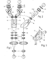
- Fig. 1 in Vorderansicht und in Seitenansicht schema-
- und 2 tisch den Aufbau eines Stereomikroskops mit einem in den Strahlengang des mikroskopisch eingeschobenen 90°-Reflektions-Prisma,
- Fig. 3 in perspektivischer Ansicht das 90°-Reflektions-Prisma,
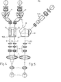
- Fig. 4 in Draufsicht und in Seitenansicht in sche-
- und 5 matischer Darstellung den Strahlengang eines Stereomikroskops mit einem in den Strahlengang eingeschobenen reflektierenden System aus zwei winklig zueinander angeordneten Spiegeln,
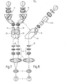
- Fig. 6 in perspektivischer Darstellung ein erfindungsgemäßes Stereomikroskop entsprechend dem Aufbau nach Fig.4 und 5 und
- Fig. 7 in Ansicht und in Seitenansicht den Strahlen-und 8 gang des erfindungsgemäß ausgebildeten Stereomikroskops nach den Fig.l bis 6 mit einem das reflektierende System ersetzenden Reflektionsprisma.
- 1 in front view and in side view schematic
- and 2 table the setup of a stereomicroscope with a 90 ° reflection prism inserted into the beam path of the microscopic,
- 3 is a perspective view of the 90 ° reflection prism,
- 4 in plan view and in side view in sche-
- 5 shows a mathematical representation of the beam path of a stereomicroscope with a reflecting system inserted into the beam path and consisting of two mirrors arranged at an angle to one another,
- Fig. 6 is a perspective view of a stereo microscope p according to the invention according to the structure of Figures 4 and 5 and
- 7 shows a view and a side view of the beam path and 8 path of the stereomicroscope according to the invention designed according to FIGS. 1 to 6 with a reflection prism replacing the reflecting system.
In den Figuren ist mit 1 das Stereomikroskop insgesamt bezeichnet. Unter dem Mikroskop ist eine Kugellinse 2, die zusammen mit einer auf das Auge 3 aufgesetzten Kontaktlinse die Funduskopie-Einrichtung bildet. Hierdurch wird der Gesichtsfeldwinkel des Stereomikroskops, der normalerweise bis zu 300 beträgt, auf 150° erweitert, was einen erheblich größeren Überblick bei Beobachtungen im Auge bedeutet.The stereomicroscope is designated as a whole in the figures by 1. Under the microscope is a
Das Stereomikroskop 1 hat bis auf das in den parallelen Strahlengang des Mikroskops eingefügte 900-Reflektionsprisma 4 mit einem Dachflächenpaar einen konventionellen Aufbau. Die Sammellinse 7 des Stereomikroskops 1 ist beiden Strahlengängen 8, 9 gemeinsam. Der Sammellinse ist für jeden Strahlengang ein Vergrößerungswechsler 6 nachgeschaltet, mit dem in einfacher Weise die Vergrößerung des Stereomikroskops 1 einstellbar ist. Dieser Vergrößerungswechsler ist konventioneller Art und kann als Walzenwechsler ausgebildet sein. Dem Vergrößerungswechsler 6 ist in bekannter Weise in jedem Strahlengang 8, 9 eine Objektivlinse 10 nachgeschaltet. Die beiden Okulartuben 11, 12 bilden ein Fernrohrsystem mit jeweils drei Linsen, 13, 14, zwischen denen Umlenkprismen 15, 16 zugeordnet sind. Der Aufbau der Okulartuben 11, 12 ist herkömmlicher Art.The
Bei dem erfindungsgemäßen Stereomikroskop wurde gegenüber einem herkömmlichen Stereomikroskop der Abstand zwischen dem Vergrößerungswechsler 6 sowie den beiden Okulartuben 11, 12 vergrößert und das Reflektionsprisma 4 gemäß Fig. 3 mit seinen beiden Dachflächen 17, 18 eingefügt. Dieses 90°-Reflektionsprisma ergibt ein gedrehtes, ungespiegeltes Bild, das in die Okulartuben 11, 12 eingespiegelt wird, die, wie Fig. 2 zeigt, in einem Winkel zum Strahlengang 8, 9 angeordnet sind. Für Operationsstereomikroskope ist diese Abwicklung unbedingt erforderlich, da dann nur in ergonomischer Hinsicht in einwandfreier Weise die Operation durchgeführt werden kann. Der Austausch des Prismas 4 durch ein anderes Prisma, das keine Strahlenablenkung in einem bestimmten Winkel zuläßt, ist für den genannten Einsatzzweck nicht zu verwenden.In the stereomicroscope according to the invention, the distance between the
In den Fig. 4 und 5 ist das gleiche Stereomikroskop in Ansicht und Seitenansicht gezeigt, wobei dessen grundsätzlicher Aufbau dem des Stereomikroskops nach Fig. 1 und 2 entspricht. Gleiche-Teile sind hier mit gleichen Bezugszeichen versehen. Der Unterschied zu dem Ausführungsbeispiel nach Fig. 1 und 2 besteht darin, daß hier anstelle eines 90°-Reflektionsprismas mit Dachkanten zwei Spiegel 19, 20 in den Strahlengang 8, 9 eingeschaltet sind, die das geforderte gedrehte, ungespiegelte Bild liefern, das dann in die Okulartuben 11, 12, die wiederum in einem Winkel zum Strahlengang 8, 9 angeordnet sind, eingeleitet wird. Die Funktionsweise dieses Stereomikroskops ist die gleiche wie die nach den Fig. 1 und 2 beschriebene. In Fig. 6 ist in schematisierter und perspektivischer Darstellung ein Stereomikroskop entsprechend Fig. 4 und 5 dargestellt. Bei diesem Stereomi- kroskop sind gleiche Teile mit gleichen Bezugszeichen versehen. Der Unterschied zu der Prinzipskizze nach den Fig. 3 und 4 besteht darin, daß die Sammelllinse 7 und die Linse 2 in einem Gehäuse 21 angeordnet sind, das zum einen eine Verschiebung der Linse 2 relativ zur Sammellinse 7 gestattet und das zum anderen auf einem Träger 22 befestigt ist, welcher um eine Achse 23 schwenkbar ist, so daß die Weitwinkeleinrichtung 21 bei Nichtgebrauch durch die für die Beobachtung des Augenvordergrundes benötigte Sammellinse 7 durch einfaches Verschwenken austauschbar ist.4 and 5, the same stereomicroscope is shown in a view and a side view, the basic structure of which corresponds to that of the stereomicroscope according to FIGS. 1 and 2. Identical parts are provided with the same reference symbols here. The difference to the embodiment according to FIGS. 1 and 2 is that here instead of a 90 ° reflection prism with roof edges two
Im Gehäuse 23 des Stereomikroskops ist das doppelt brechende Spiegelsystem 19, 20 angeordnet. Dieses doppelt brechende Spiegelsystem 19, 20 sitzt auf einem nicht dargestellten Schlitten, zusammen mit einem Pentagonalprisma 24, das dem Spiegelsystem 19, 20 so angepaßt ist, daß die Strahlen 8, 9 im Spiegelsystem 19, 20 wie auch im Pentagonalprisma 24 den gleichen optischen Weg zurücklegen. Falls das Stereomikroskop nicht zur Operation des Augenhintergrundes verwendet werden soll, sondern zu anderweitigen Operationen oder aber für Eingriffe vor der Augenlinse, dann wird, um hier wiederum ein aufrechtes Bild zu erhalten, das Spiegelsystem 19, 20 aus dem Strahlengang 8, 9 herausgefahren und das Pentagonalprisma an die Stelle des Spiegelsystems 19, 20 gefahren. Dieser Wechsel muß bei Augenoperationen öfter durchgeführt werden, da der Eingriff zunächst an der Augenperipherie stattfindet und erst dann der Augenhintergrund operiert wird. Dadurch, daß sowohl das Pentagonalprisma 23 wie auch das Spiegelsystem 19, 20 und auch das 90°-Reflektionsprisma mit Dachflächenpaar 17, 18 den gleichen optischen Weg aufweist, ist bei einem Austausch der Spiegelsysteme gewährleistet, daß das erhaltene Bild sofort wieder scharf ist, so daß Nachstellarbeiten zur Scharfjustierung entfallen.The
In den Fig. 7 und 8, die ein Stereomikroskop entsprechend Fig. 1 und 2 bzw. Fig. 4 bis 6 zeigen, sind der schematische Aufbau des Stereomikroskops und der Strahlengang nach dem Einschieben des Pentagonalprismas 24 in den Strahlengang dargestellt.7 and 8, which show a stereomicroscope p corresponding to FIGS. 1 and 2 or FIGS. 4 to 6, show the schematic structure of the stereomicroscope and the beam path after the
Claims (5)
Applications Claiming Priority (2)
| Application Number | Priority Date | Filing Date | Title |
|---|---|---|---|
| DE19853507458 DE3507458A1 (en) | 1985-03-02 | 1985-03-02 | STEREOMICROSCOPE FOR OPERATIONS |
| DE3507458 | 1985-03-02 |
Publications (1)
| Publication Number | Publication Date |
|---|---|
| EP0193818A1 true EP0193818A1 (en) | 1986-09-10 |
Family
ID=6264045
Family Applications (1)
| Application Number | Title | Priority Date | Filing Date |
|---|---|---|---|
| EP86102315A Withdrawn EP0193818A1 (en) | 1985-03-02 | 1986-02-22 | Stereo microscope for operations |
Country Status (4)
| Country | Link |
|---|---|
| US (1) | US4710000A (en) |
| EP (1) | EP0193818A1 (en) |
| JP (1) | JPH061298B2 (en) |
| DE (1) | DE3507458A1 (en) |
Cited By (5)
| Publication number | Priority date | Publication date | Assignee | Title |
|---|---|---|---|---|
| EP0236921A2 (en) * | 1986-03-14 | 1987-09-16 | Oculus Optikgeräte GmbH | Supplementary device for microscopes |
| DE3826069A1 (en) * | 1988-07-30 | 1990-02-01 | Oculus Optikgeraete Gmbh | PRISM SYSTEM FOR A STEREOSCOPIC MICROSCOPE |
| WO1998020378A1 (en) * | 1996-11-08 | 1998-05-14 | Volk Optical Inc. | Image reinverter for stereo microscope |
| US6598972B2 (en) | 2000-09-26 | 2003-07-29 | Carl Zeiss-Stiftung | Stereomicroscopy system |
| DE102015007786A1 (en) * | 2015-06-19 | 2016-12-22 | Carl Zeiss Meditec Ag | Stereomicroscope with heterophoria compensation |
Families Citing this family (27)
| Publication number | Priority date | Publication date | Assignee | Title |
|---|---|---|---|---|
| DE3539009A1 (en) * | 1985-11-02 | 1987-05-07 | Moeller J D Optik | Attachment for a stereoscopic surgical microscope for ophthalmic surgery |
| FR2651668B1 (en) * | 1989-09-12 | 1991-12-27 | Leon Claude | MICROSCOPE-ENDOSCOPE ASSEMBLY USEFUL IN PARTICULAR IN SURGERY. |
| US5270747A (en) * | 1989-12-14 | 1993-12-14 | Kabushiki Kaisha Topcon | Stereomicroscope with first and second illuminating systems |
| US5438456A (en) * | 1991-03-14 | 1995-08-01 | Grinblat; Avi | Optical stereoscopic microscope system |
| DE4114646C2 (en) * | 1991-05-04 | 1996-02-29 | Zeiss Carl Fa | Ophthalmoscope attachment for a surgical microscope |
| US5321447A (en) * | 1991-05-04 | 1994-06-14 | Carl-Zeiss-Stiftung | Ophthalmoscopic attachment for a surgical microscope |
| US5400092A (en) * | 1991-12-17 | 1995-03-21 | Mira, Inc. | Binocular ophthalmoscope |
| US5359373A (en) * | 1992-01-24 | 1994-10-25 | The Trustees Of Columbia University In The City Of New York | High resolution contact lens structure in combination with a microscope objective |
| WO1994010596A1 (en) * | 1992-10-23 | 1994-05-11 | Avi Grinblat | Optical stereoscopic microscope system |
| DE4336715C2 (en) * | 1992-10-27 | 1999-07-08 | Olympus Optical Co | Stereo microscope |
| US5673147A (en) * | 1995-04-18 | 1997-09-30 | Mckinley Optics, Inc. | Stereo video endoscope objective lens systems |
| US5652639A (en) * | 1996-02-28 | 1997-07-29 | Patel; Achyut S. | Indirect ophthalmoscope producing an erect stereoscopic image |
| JP3889849B2 (en) * | 1996-05-08 | 2007-03-07 | オリンパス株式会社 | Microscope objective lens and single objective binocular stereomicroscope system |
| DE29905969U1 (en) * | 1999-04-08 | 1999-07-08 | Oculus Optikgeraete Gmbh | Stereoscopic microscope |
| US6120145A (en) * | 1999-06-28 | 2000-09-19 | Ld3, Inc. | Surgical loupes apparatus |
| US7061672B2 (en) * | 2000-06-20 | 2006-06-13 | Kramer Scientific Corporation | Fluorescence microscope |
| JP2004510198A (en) * | 2000-09-26 | 2004-04-02 | カール−ツアイス−スチフツング | Image reversal system, ophthalmoscope auxiliary module, surgical microscope |
| JP4804649B2 (en) * | 2001-05-29 | 2011-11-02 | 株式会社トプコン | Stereo microscope |
| US20030169603A1 (en) * | 2002-03-05 | 2003-09-11 | Luloh K. Peter | Apparatus and method for illuminating a field of view within an eye |
| KR20040050008A (en) * | 2002-12-09 | 2004-06-14 | 양연식 | upright indirect ophthalmoscope |
| EP1498762A1 (en) * | 2003-07-17 | 2005-01-19 | Leica Microsystems (Schweiz) AG | Microscope |
| DE10336475B9 (en) * | 2003-08-08 | 2006-09-07 | Carl Zeiss | microscopy system |
| US20060270908A1 (en) * | 2005-05-18 | 2006-11-30 | Luloh K P | Self Inserting Intraolcular Light |
| JP5184752B2 (en) * | 2006-03-27 | 2013-04-17 | オリンパス株式会社 | Stereo microscope |
| WO2009074161A1 (en) * | 2007-12-10 | 2009-06-18 | Carl Zeiss Surgical Gmbh | Head-mountable loupe |
| US9693686B2 (en) * | 2015-04-30 | 2017-07-04 | Novartis Ag | Ophthalmic visualization devices, systems, and methods |
| JP2017191122A (en) * | 2016-04-11 | 2017-10-19 | 三鷹光器株式会社 | Surgical microscope |
Citations (5)
| Publication number | Priority date | Publication date | Assignee | Title |
|---|---|---|---|---|
| GB843888A (en) * | 1958-06-26 | 1960-08-10 | Arthur Abbey | Improvements in or relating to stereoscopic microscopes |
| CH560908A5 (en) * | 1974-02-19 | 1975-04-15 | Wild Heerbrugg Ag | |
| US3909106A (en) * | 1974-03-19 | 1975-09-30 | Applied Fiberoptics | Inclined prism ocular systems for stereomicroscope |
| US4009930A (en) * | 1975-04-23 | 1977-03-01 | Konan Camera Research Institute | Binomial microscope |
| EP0090982A1 (en) * | 1982-04-05 | 1983-10-12 | Firma Carl Zeiss | Prism compensator for stereoscopic viewing instruments |
Family Cites Families (2)
| Publication number | Priority date | Publication date | Assignee | Title |
|---|---|---|---|---|
| US2119545A (en) * | 1937-03-22 | 1938-06-07 | Otto K Kaspereit | Prism |
| US3405990A (en) * | 1965-06-25 | 1968-10-15 | Bausch & Lomb | Coaxial illuminator for stereomicroscope |
-
1985
- 1985-03-02 DE DE19853507458 patent/DE3507458A1/en not_active Withdrawn
-
1986
- 1986-02-22 EP EP86102315A patent/EP0193818A1/en not_active Withdrawn
- 1986-02-28 US US06/834,943 patent/US4710000A/en not_active Expired - Fee Related
- 1986-03-03 JP JP61044287A patent/JPH061298B2/en not_active Expired - Fee Related
Patent Citations (5)
| Publication number | Priority date | Publication date | Assignee | Title |
|---|---|---|---|---|
| GB843888A (en) * | 1958-06-26 | 1960-08-10 | Arthur Abbey | Improvements in or relating to stereoscopic microscopes |
| CH560908A5 (en) * | 1974-02-19 | 1975-04-15 | Wild Heerbrugg Ag | |
| US3909106A (en) * | 1974-03-19 | 1975-09-30 | Applied Fiberoptics | Inclined prism ocular systems for stereomicroscope |
| US4009930A (en) * | 1975-04-23 | 1977-03-01 | Konan Camera Research Institute | Binomial microscope |
| EP0090982A1 (en) * | 1982-04-05 | 1983-10-12 | Firma Carl Zeiss | Prism compensator for stereoscopic viewing instruments |
Cited By (7)
| Publication number | Priority date | Publication date | Assignee | Title |
|---|---|---|---|---|
| EP0236921A2 (en) * | 1986-03-14 | 1987-09-16 | Oculus Optikgeräte GmbH | Supplementary device for microscopes |
| EP0236921A3 (en) * | 1986-03-14 | 1990-06-13 | Oculus Optikgerate Gmbh | Supplementary device for microscopes |
| DE3826069A1 (en) * | 1988-07-30 | 1990-02-01 | Oculus Optikgeraete Gmbh | PRISM SYSTEM FOR A STEREOSCOPIC MICROSCOPE |
| WO1998020378A1 (en) * | 1996-11-08 | 1998-05-14 | Volk Optical Inc. | Image reinverter for stereo microscope |
| US5986801A (en) * | 1996-11-08 | 1999-11-16 | Volk; Donald A. | Image reinverter for stereo microscope |
| US6598972B2 (en) | 2000-09-26 | 2003-07-29 | Carl Zeiss-Stiftung | Stereomicroscopy system |
| DE102015007786A1 (en) * | 2015-06-19 | 2016-12-22 | Carl Zeiss Meditec Ag | Stereomicroscope with heterophoria compensation |
Also Published As
| Publication number | Publication date |
|---|---|
| JPS61269108A (en) | 1986-11-28 |
| JPH061298B2 (en) | 1994-01-05 |
| DE3507458A1 (en) | 1986-09-04 |
| US4710000A (en) | 1987-12-01 |
Similar Documents
| Publication | Publication Date | Title |
|---|---|---|
| EP0193818A1 (en) | Stereo microscope for operations | |
| EP1326117B2 (en) | Ophthalmoscopic front end attachment and surgical microscope | |
| DE4227390C2 (en) | Ophthalmic device | |
| DE102004050893B4 (en) | Tube with two switchable planar optical elements for optional beam exchange and image reversal for a microscope and microscope | |
| DE4331635C2 (en) | Illumination device for an operating microscope with optically-mechanically coupled observer tubes | |
| EP1320779B1 (en) | Image reversion system, additional ophthalmoscopy module and operational microscope | |
| DE4116385A1 (en) | STEREOSCOPIC MICROSCOPE | |
| DE4114646A1 (en) | OPHTHALMOSCOPY ATTACHMENT FOR SURGICAL MICROSCOPE | |
| DE3515004C2 (en) | Stereo microscope | |
| DE3539009A1 (en) | Attachment for a stereoscopic surgical microscope for ophthalmic surgery | |
| DE10347732B4 (en) | Lighting device and surgical microscope and their use | |
| EP1460466B1 (en) | Microscope, in particular stereomicroscope | |
| DE3615842A1 (en) | INTERMEDIATE ASSEMBLY FOR A STEREOSCOPIC OPERATING MICROSCOPE FOR EYE SURGERY | |
| EP0492044A1 (en) | Vision test device | |
| DE19546746B4 (en) | Zoom system for at least two stereoscopic observation beam paths | |
| CH670372A5 (en) | ||
| DE19503575B4 (en) | Binocular tube for a stereomicroscope | |
| DE4320580A1 (en) | Binocular stereo microscope with two optical paths - has multiple reflector for reflected light passed through imaging lens, guiding light to side of optical axis | |
| DE19640976C2 (en) | Optical system for a laser slit lamp | |
| DE19532400B4 (en) | Stereo endoscope with angled viewing direction | |
| EP1498762A1 (en) | Microscope | |
| DE3546915C2 (en) | Single objective stereo microscope | |
| DE10312681A1 (en) | Microscope system, with two deflection mirrors in front of a lens, gives views of the specimen from a variety of angles without moving the microscope chassis | |
| DE10332602B3 (en) | Stereo optical microscope for intraocular surgery has main objective followed by magnification system with perpendicualr optical axis | |
| DE3627251A1 (en) | Stereoscopic ophthalmoscope |
Legal Events
| Date | Code | Title | Description |
|---|---|---|---|
| PUAI | Public reference made under article 153(3) epc to a published international application that has entered the european phase |
Free format text: ORIGINAL CODE: 0009012 |
|
| AK | Designated contracting states |
Kind code of ref document: A1 Designated state(s): DE FR GB IT |
|
| 17P | Request for examination filed |
Effective date: 19861009 |
|
| 17Q | First examination report despatched |
Effective date: 19870915 |
|
| STAA | Information on the status of an ep patent application or granted ep patent |
Free format text: STATUS: THE APPLICATION IS DEEMED TO BE WITHDRAWN |
|
| 18D | Application deemed to be withdrawn |
Effective date: 19881018 |
|
| RIN1 | Information on inventor provided before grant (corrected) |
Inventor name: SPITZNAS, MANFRED, PROF. DR. Inventor name: KIRCHHUEBEL, RAINER, DIPL.-ING. Inventor name: REINER, JOSEF, PROF. DR. Inventor name: VEIT, WOLFGANG |