EP1227354A2 - Katadioptrisches Reduktionsobjektiv - Google Patents
Katadioptrisches Reduktionsobjektiv Download PDFInfo
- Publication number
- EP1227354A2 EP1227354A2 EP02000562A EP02000562A EP1227354A2 EP 1227354 A2 EP1227354 A2 EP 1227354A2 EP 02000562 A EP02000562 A EP 02000562A EP 02000562 A EP02000562 A EP 02000562A EP 1227354 A2 EP1227354 A2 EP 1227354A2
- Authority
- EP
- European Patent Office
- Prior art keywords
- beam splitter
- lens
- projection objective
- mirror
- image
- Prior art date
- Legal status (The legal status is an assumption and is not a legal conclusion. Google has not performed a legal analysis and makes no representation as to the accuracy of the status listed.)
- Withdrawn
Links
Images

Classifications
-
- G—PHYSICS
- G02—OPTICS
- G02B—OPTICAL ELEMENTS, SYSTEMS OR APPARATUS
- G02B17/00—Systems with reflecting surfaces, with or without refracting elements
- G02B17/08—Catadioptric systems
- G02B17/0892—Catadioptric systems specially adapted for the UV
-
- G—PHYSICS
- G02—OPTICS
- G02B—OPTICAL ELEMENTS, SYSTEMS OR APPARATUS
- G02B17/00—Systems with reflecting surfaces, with or without refracting elements
- G02B17/08—Catadioptric systems
-
- G—PHYSICS
- G03—PHOTOGRAPHY; CINEMATOGRAPHY; ANALOGOUS TECHNIQUES USING WAVES OTHER THAN OPTICAL WAVES; ELECTROGRAPHY; HOLOGRAPHY
- G03F—PHOTOMECHANICAL PRODUCTION OF TEXTURED OR PATTERNED SURFACES, e.g. FOR PRINTING, FOR PROCESSING OF SEMICONDUCTOR DEVICES; MATERIALS THEREFOR; ORIGINALS THEREFOR; APPARATUS SPECIALLY ADAPTED THEREFOR
- G03F7/00—Photomechanical, e.g. photolithographic, production of textured or patterned surfaces, e.g. printing surfaces; Materials therefor, e.g. comprising photoresists; Apparatus specially adapted therefor
- G03F7/70—Microphotolithographic exposure; Apparatus therefor
- G03F7/70216—Mask projection systems
- G03F7/70225—Optical aspects of catadioptric systems, i.e. comprising reflective and refractive elements
Definitions
- the invention relates to a catadioptric projection lens for imaging a pattern arranged in an object plane into an image plane.
- Such projection lenses are used in projection exposure systems for the production of semiconductor components and other finely structured Components used, especially in wafer scanners and wafer steppers. They are used to make patterns from photomasks or graticules hereinafter generally referred to as masks or reticles an object coated with a light-sensitive layer to project the highest resolution on a smaller scale.
- NA numerical aperture
- a system with a physical beam splitter and intermediate image is from the EP-A-0 475 020 (corresponding to US 5,052,763) is known.
- This system has at least one catadioptric entrance system and one dioptric Output System.
- the mask to be imaged lies directly on one Beam splitter, which is designed as a beam splitter cube (BSC) is.
- BSC beam splitter cube
- EP-A-0 350 955 (corresponding to US-A-4,953,960) is a catadioptric Projection lens known without an intermediate image, in which between the object plane and a physical beam splitter a first Lens group, between the physical beam splitter and a concave mirror a second lens group and between the physical Beam splitter and the image plane, a third lens group is provided.
- the lens group arranged between the beam splitter and concave mirror Low order coma and spherical aberration of the mirror as well correct the Gaussian error.
- DE-A-42 03 464 (corresponding to US-A-5,402,267) is a catadioptric Projection lens with and without a physical beam splitter Intermediate image known, that with a favorable design and low adjustment sensitivity high image-side numerical apertures of at least 0.5 enables.
- the main characteristic of this system is that that no lens group between the concave mirror and the beam splitter is arranged and that the concave mirror has a significant reduction effect, thus has a greatly reducing image scale.
- the correction longitudinal chromatic aberration (CHL) becomes essentially achieved by a strongly convergent beam path in beam splitter cubes and can lead to full achromatization of the longitudinal chromatic aberration to lead.
- the beam path in front of the mirror is typically i.e.
- the system diaphragm is preferably located at the location of the concave mirror and is defined by its edge.
- the bezel can also be on the mirror side Interface of the beam splitter or between the mirror and the beam splitter be defined.
- type I lenses are offset by a disadvantage that the radiation especially during the second pass after reflection from the concave mirror converges on the beam splitter surface, so that a very large incidence angle range occurs. This places increased demands the quality of the beam splitter layer. It also leads to strong convergence the beam path after the concave mirror that behind the Beam splitter only little space for lenses and therefore few correction agents be available. A further increase in the numerical image side Aperture would require enlarging the beam splitter cube and further condition that the image plane be even closer to the beam splitter draws near. Therefore, type I projection lenses are also considered to be aperture limited.
- From US-A-5,771,125 is an intermediate image-free, catadioptric projection system known with physical beam splitter, in which the Radiation in the first pass through the beam splitter layer is weakly divergent, while in the second pass after reflection on the concave mirror is collimated. This is said to cause deterioration in image quality the dependence of the reflectance of the beam splitter layer on Incidence angles are avoided.
- the collimation of the reflected light is achieved in that the refractive power of the concave mirror Mirror group is kept relatively low.
- EP-A-0 602 923 (corresponding to US-A-5,715,084), however, is before the physical Beam splitter provided a positive lens to the first Passage collimating radiation falling on the beam splitter layer. After reflection at the concave mirror, it is convergent.
- a catadioptric projection lens to indicate with physical beam splitting, the disadvantages of the stand who avoids technology.
- an almost complete chromatic correction are made possible. This should be done with little material with regard to mass and / or number of optical components can be achieved.
- the invention proposes a catadioptric Projection lens with the features of claim 1.
- advantageous Developments are specified in the dependent claims. The wording of all claims becomes the content of the Description made.
- a catadioptric projection lens according to the invention which has an in the pattern of objects arranged in a picture plane has between Object level and image level in this order a first Objective part for generating a directed at a physical beam splitter Beam, a physical beam splitter with a beam splitter surface, a mirror group with a concave mirror or concave mirror and a mirror group refractive power and a second lens part with positive Refractive power to produce an image of the pattern in the image plane, wherein the mirror group refractive power is large and the system aperture on the image side lies behind the concave mirror.
- the large refractive power of the mirror group enables beam guidance, at which strikes the mirror group divergently and converges direction Beam splitter area emerges. This makes it possible for the beam splitter both in the first run and in the second run with non-collimated Light is shone through and due to the oblique passage of light can contribute to the chromatic correction.
- Advantageous for this is when the sum of the amounts of the paraxial edge ray angles at first pass and the second pass is large towards zero.
- the sum total of the paraxial marginal jet angles is preferably included more than 30% or 40% of the numerical aperture, in particular it can are in the range of 60% of the numerical aperture.
- the system aperture is the axial location at which the main beam intersects the optical axis.
- a position is preferred the system aperture between the beam splitter surface and the image plane, in particular close to or on the image-side exit surface of the beam splitter.
- the Mapping is preferably done without generating an intermediate image.
- the first lens part is designed so that on the Beam part directed divergent beam is generated.
- Preferred are strong divergent rays, in which edge ray angles occur, the larger than about 20% of the numerical aperture on the image side and, for example, in the Range between 30% and 40% of the numerical aperture on the image side can.
- the product of the refractive index is the edge ray angle u n of the medium flowing through and the sine of the angle between the edge beam and the optical axis.
- a strong beam divergence with favorable lens part diameters is achieved in preferred embodiments in that the first lens part negative refractive power in front of the beam splitter, preferably at least has two negative lenses for generating a waist in the beam path.
- the mirror group refractive power is so large that that the beam is convergent behind the mirror group on the image side.
- the edge beam angle that is greater than approximately 10% of the numerical image side Aperture of the projection lens is.
- the edge beam angle approx. 30% of the numerical aperture on the image side not or not significantly exceed.
- the amount of the edge beam angle in the first pass is expedient larger in front of the mirror group than after reflection on the mirror.
- Preferably is a strong divergence in front of the mirror in a magnitude weaker convergence after the mirror is converted so that the essential Contribution to chromatic correction from the very first step done by the beam splitter.
- Embodiments in which between the Beam splitter surface and the concave mirror no free-standing lens arranged is.
- the concave mirror preferably has a magnifying magnification. It carries with great refractive power and without chromatic Introduce aberrations to the total power. He also corrects the Petzval sum of the projection lens.
- the invention makes it possible to carry out the chromatic correction for the most part before entering the second objective part, that is to say especially in the area of the beam splitter and mirror group. Therefore, the second lens part can be constructed particularly cheap in terms of dimensioning and material requirements. In particular, it is not necessary to provide highly effective chromatic correction means, so that the second lens part, at least in the region of large beam heights, ie at a certain distance from the image plane, can have lenses made from only a single material.
- Embodiments of the invention are characterized in that essentially all transparent optical components consist of a single material, for example calcium fluoride or fluorspar (CaF 2 ) or synthetic quartz glass (SiO 2 ).
- a second radiation-insensitive material such as CaF 2
- the lens material used predominantly or exclusively can thus be calcium fluoride or another fluoridic crystal material, in particular if the system is designed for wavelengths of less than approx. 160 nm. For longer wavelengths, for example around 193 nm, a predominant or exclusive use of synthetic quartz glass is also possible.
- a or several aspherical surfaces can be provided, usually a larger number of aspheres is provided, but preferably not more than eight. It is particularly with a view to correcting the spherical aberration and of coma expedient if at least an aspherical surface is arranged in the area of the system cover. A particularly effective correction is given here if for this Area the ratio h / ⁇ between the edge ray height h on the area and the radius ⁇ of the opening of the system cover between approx. 0.8 and approx. 1.2 lies. The edge jet height should therefore be close to the aspherical surface the maximum edge jet height.
- At least one aspherical surface is provided near the field, i.e. close to Reticle, or on the object plane and / or close to the wafer or the image plane.
- These close to the field Areas are characterized by the fact that the ratio h / ⁇ is smaller for you than about 0.8. It is favorable if at least one asphere is close to the field and arranged at least one asphere in the vicinity of the system bezel is. This makes it possible for all of the imaging errors addressed to provide a sufficient correction.
- optical axis means a straight line or a sequence of straight line sections through the centers of curvature of the optical Components.
- the optical axis is at deflecting mirrors or reflective surfaces folded. Directions and distances are considered described on the image side if they are in the direction of the image plane or there located substrate to be exposed and are directed as "object side", if they are directed towards the object with respect to the optical axis.
- the object is a mask (reticle) with the pattern of a integrated circuit, but it can also be a different pattern, for example a grid.
- the picture is in the examples on a serving as a substrate provided with a photoresist layer Wafers are formed, but there are also other substrates, for example elements for liquid crystal displays or substrates for optical gratings.
- substrates for example elements for liquid crystal displays or substrates for optical gratings.
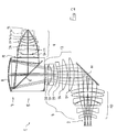
- a typical construction of a catadioptric reduction lens according to the invention 1 is based on a first exemplary embodiment in FIG. 1 shown. It serves a pattern arranged in an object plane 2 a reticle or the like in an image plane 3 on a reduced scale map, for example in a ratio of 4: 1.
- the lens 1 has between the object level 2 and the image level 3 in the specified order a first objective part 4, a physical beam splitter 5 with a beam splitter surface 6, a mirror group 7 with a concave mirror 8 and a second lens part 9 connected downstream of the beam splitter with positive ones Power to create an image of the pattern in the image plane Third
- the first lens part 4 has a first following the object plane 2 Lens group 10, a flat, inclined at 45 ° to the optical axis Deflecting mirror 11 and between this and the beam splitter 5 a second lens group 12.
- the deflecting mirror 11 makes it possible in connection with the beam splitter 5, the mask arranged in the object plane 2 to be aligned parallel to the wafer arranged in the image plane 3, whereby scanner operation of the mask and wafer is facilitated.
- the angled shape of the first part of the object is also a straight shape without Deflecting mirror 11 possible.
- the light emerges from an illumination system (not shown) on the opposite side of the object plane 2 in the projection lens and thereby passes through the one arranged in the image plane Mask.
- the transmitted light passes through the first lens group 10, is on the deflecting mirror 11 in the direction of the second lens group 12 reflects and passes through this direction beam splitter 5.
- Passes through the beam splitter the light is inclined at an angle of approx. 45 ° to the optical axis, flat beam splitter surface 6 and falls after passing through a Quarter wave plate (not shown) on the concave reflecting surface of the concave mirror 8. From this reflected the light passes through again Quarter wave plate before it hits the beam splitter layer 6 which is the light now reflected towards image plane 3.
- the light passes through the second lens part 9, which shows an image of the mask a light-sensitive surface of the wafer arranged in the image plane generated.
- the first lens group 10 comprises, starting from the object plane 2 one biconcave negative lens 15, another biconcave negative lens 16, a meniscus lens 17, the concave surface F5 of which faces the object plane 2, a biconvex lens 18 with a slightly curved object-side Surface, another biconvex lens 19 with a slightly curved object-side Surface and a mini lens 20 with an object-side concave Area.
- the second lens group 12 following the deflecting mirror 11 begins with a meniscus lens 21 with a concave surface F13 on the object, on the one reversed curved mini lens 22 follows, the object-side surface F15 is convex.
- a negative lens 23 follows at an axial distance from the meniscus group 21, 22 with a strongly concave curved exit surface F18 onto another biconcave Negative lens 24 follows.
- the beam splitter 5 comprises two in the area the beam splitter surface 6 interconnected rectangular prisms, which form a beam splitter cube (BSC).
- BSC beam splitter cube
- Embodiments is a different from the cube shape Form provided, for example a regular or irregular Minimal form with regard to the material volume, which is related to the beam path within of the beam splitter is adapted so that essentially no non-irradiated ones Areas exist.
- a thin optically effective layer is provided, which in the shown Embodiment is constructed so that the first lens part 4 coming polarized light is transmitted and that from the mirror 8 light coming after passing through the quarter-wavelength layer twice and an associated rotation of the preferred polarization direction is reflected by 90 ° in the direction of the image plane. So it's about a polarization beam splitter in which light losses compared to also partially permeable mirror layers in the area of Beam splitter area are minimized.
- the beam splitter surface 6 provided beam splitter layer designed so that the light coming first lens part initially in the direction of a concave mirror is reflected, that on the opposite of the second lens part 9 Side of the beam splitter. That from this concave mirror reflected light is passed through a quarter-wavelength layer twice from this beam splitter layer 6 then in the direction of the image plane 3 transmitted. It is an alternative to the beam splitters described also possible to insert a physical beam splitter through a slant in the Realize the plane-parallel plate provided.
- the light After emerging from the beam splitter 5, the light enters the second lens part 9 a.
- Table 1 shows the specification of the design in a known manner in summarized in tabular form.
- Column 1 gives the number of refractive or reflecting surface F
- column 2 the radius r of the surface (in mm)
- column 3 the distance d of the surface, which is called the thickness to the following area (in mm)
- column 4 the one designated as index Refractive index of the material of the component, that of the entry surface follows.
- Column 5 shows the reflective surfaces.
- the numerical aperture NA on the image side is 0.85.
- the intermediate image-free system is characterized by some in the following special features explained in more detail.
- the upstream of the mirror 11 first lens group 10 has positive refractive power around that coming from the object Bundle light. This occurs after reflection on the deflecting mirror 11 into the second lens group 12.
- the two curved in opposite directions Menisci 21, 22 have at the entrance of the second lens part in total positive refractive power and further narrow the beam diameter so that the group of three lenses 23, 24 and 25 which follow at a great distance can be constructed from lenses with a small diameter.
- the converging Radiation is through the triple, essentially through the two immediately successive negative lenses 23 and 24 below Formation of a waist in the beam path in a strongly divergent Radiation converted onto the entry surface F24 of the beam splitter 5 meets.
- the beam splitter cube can be kept small.
- the divergent radiation passes through the beam splitter surface 6 in the direction of the concave mirror 8.
- the curvature of its reflecting surface F26 is dimensioned so that the radiation reflected by the mirror is indeed convergent, the However, the amount of the maximum edge jet angle is smaller than that the incident divergent radiation.
- Preferred values for the maximum Edge ray angle in the second pass after reflection on the mirror are between approx. 10% and approx. 30% of the numerical aperture on the image side. It is achieved on the one hand that the incidence of light in the second Passage is so oblique that the beam splitter cube contributes to can perform chromatic correction.
- the amount is the maximum paraxial edge ray angle in the first pass between first lens part and mirror at approx. 35% and in the second pass behind the mirror at about 23% of the numerical aperture.
- the system cover A is in the embodiment shown in the range immediately after the radiation emerges from the beam splitter cube 5 even with high numerical apertures, the beam heights in the second lens part 9 kept relatively low, which is a cheap construction of the second lens part, particularly with regard to the cost of materials allows.
- the second lens part 9 is advantageously constructed so that the radiation collected for image generation without edge beam expansion to image level 3 becomes.
- the system aperture is behind the beam splitter lies.
- the following considerations are based on this: a large numerical one Aperture requires a large mirror diameter and therefore one large distance between concave mirror and image plane or wafer.
- the Lagrangian invariant, applied to the pupil imaging is the main beam angle coupled to the diameter of the aperture in the sense that a small aperture diameter has a large main beam angle conditionally and vice versa.
- the beam splitter block so long that the main beam height at the exit of the beam splitter block is already very large might be larger than the image height.
- the lenses of the second lens part 9 no favorable refractive power distribution found which have a telecentric main beam on the one hand and on the other hand, an extremely high (edge beam) aperture with sufficient Working distance (to the wafer) allowed.
- the The main beam By moving the system cover behind the beam splitter, the The main beam, on the other hand, passes in time when the correct image height is reached positive refractive power can be collimated. To at the same time an adequate The positive refractive power of the second will ensure working distance Lens part 9 only after a weak refractive power located in the aperture space Lens group arranged.
- the axial length of the second Lens part can be kept low. This contributes to a compact design of the entire lens 1.
- the "informal" beam guidance within the lens causes as an advantageous consequence that the at the refractive or reflective Areas of maximum occurring beam angles remain small, so that favorable Requirements for an effective increase in transmission are created by coating the surfaces.
- the maximum marginal jet angles are the maximum marginal jet angles, with the exception of three areas next to the wafer, predominantly less than 70% or 80% of the numerical aperture on the image side.
- the parameter TT Total Tracklength
- f M the focal length of the concave mirror.
- f M / TT the focal length related to the overall length.
- ⁇ M represents the magnification of the concave mirror.
- the parameters u 1 and u 2 denote the paraxial edge beam angles in front of and behind the mirror. Their size is given as a percentage of the numerical aperture NA on the image side.
- the ratio u 1 and u 2 corresponds to the image scale of the mirror.
- the working wavelength ⁇ of the embodiments is given.
- the design shown in FIG. 1 can also be used for other working wavelengths, for example for a working wavelength of approximately 193 nm, without changing the type of lens and lens arrangement, while maintaining the essential features and advantages.
- a corresponding design of a second embodiment of the invention is shown in Table 4 and Table 5 (aspheric data) using the above notation.
- synthetic quartz glass is used as the lens material.
- fluorspar CaF 2
- this does not serve to correct chromatic color errors, but rather to reduce compaction effects, ie changes in material properties due to high radiation exposure; Calcium fluoride is known to react much less sensitively than silicon dioxide.
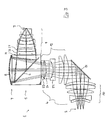
- Fig. 2 the lens section of a third embodiment is shown, the Specification in detail from Table 6 and Table 7 (aspherical data) as well Table 3 can be seen. That for a working wavelength of approx. 157 nm designed reduction lens 1 is in the basic structure of the embodiment gem. Fig. 1 similar and like this represents a numerical aperture NA of 0.85 ready for complete chromatic correction. For corresponding Lenses are given the same reference numerals as in Fig. 1. showy Differences to the design acc. Fig. 1 consist mainly in the structure of the second mirror group 12 of the first lens part 4.
- Fig. 1 the generation of the waist in Beam path through three negative lenses. Because this one is larger axial section are distributed, the waist is gentle, so that overall less heavily loaded refracting surfaces are required.
- the system aperture A attached to the exit surface of the beam splitter biconcave negative lens 26 and a meniscus lens 27 of positive refractive power.
- a meniscus lens 27 of positive refractive power is in the area before subsequent positive lenses 28-32 gathered negative refractive power larger than in the above embodiment, whereby the retrofocus effect is strengthened and a larger working distance can be achieved.
- This embodiment also avoids strongly curved lens surfaces, such as those used in the Embodiment according to Fig. 1 occur in the meniscus lens 28.
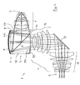
- Arrangement details and design of the optical elements used here are in the table 10 and Table 11 (aspherical data) and in Table 3.
- a comparison with the structure in Fig. 2 shows the structure of the first lens part 4 only slight differences.
- the beam expansion in the area immediately downstream of the beam splitter 5 Lenses 26, 27 are weaker than those shown above Embodiments, so that only a weak effect of the retrofocus arrangement entry. Because of the low numerical aperture nevertheless a sufficient working distance is guaranteed.
- the beam splitter 5 is one of the shape deviating from the cube shape, namely that of a beam splitter cuboid with unequal edge lengths.
- the beam splitter shape this particular Material-saving designs result from the consideration that at conventional beam splitter cubes often do not have larger volume sections contribute to the optical effect and can therefore be omitted.
- the beam splitter 5 is in terms of optical Figure minimized material volume or this minimal form at least approximated.
- this is achieved by that according to the embodiment according to. Fig. 2, the flat entrance surface F24 and the flat exit surface F29 of the beam splitter block are moved closer to the beam splitter surface 6 with parallel displacement.
- the saved by this measure compared to the beam splitter cube Excess volumes are indicated by the dashed lines 33, 34.
- the changes in position of the entry or exit surface and the associated changes Generation of a geometrically minimized beam splitter cuboid may require minor modifications to the overall design in the Comparison to the starting cube.
- the maximum irradiated material volume is preferably more than approx. 70%, in particular more than 80% of the external volume of the Beam splitter block, so that only little unused material volume remains.
- a beam splitter block can not only be used for the designs be advantageous of the invention, but also in not according to the invention Beam splitters in other catadioptric projection lenses and / or other optical devices.
- optical surfaces are especially in the embodiment for short wavelengths, for example 157 nm or less, advantageous because a for these short wavelengths adequate anti-reflective coating of surfaces often only is possible with difficulty. A reduction in the number of areas is therefore to achieve a sufficient overall transmission of the lens advantageous.
- aspherical Areas near the aperture are particularly effective for correcting the spherical aberration and coma.
- Fig. 2 also the image-side entrance surface of the following lens.
- Cheap these aspheres are used in the area of large marginal jet heights, for example, where the ratio between the marginal jet height h and the radius ⁇ of the opening of the system cover between approx. 0.8 and about 1.2.
- aspherical surfaces are for all embodiments Correction of distortion and / or other field aberrations used.
- the aspheres are arranged so that the ratio h / ⁇ between the edge jet height h and the radius ⁇ of the system aperture is smaller than about 0.8.
Landscapes
- Physics & Mathematics (AREA)
- General Physics & Mathematics (AREA)
- Optics & Photonics (AREA)
- Lenses (AREA)
- Exposure And Positioning Against Photoresist Photosensitive Materials (AREA)
- Exposure Of Semiconductors, Excluding Electron Or Ion Beam Exposure (AREA)
Abstract
Description
Claims (22)
- Katadioptrisches Projektionsobjektiv zur Abbildung eines in einer Objektebene (2) angeordneten Musters in eine Bildebene (3), wobei zwischen der Objektebene und der Bildebene in dieser Reihenfolge ein erster Objektivteil (4) zur Erzeugung eines auf einen physikalischen Strahlteiler (5) gerichteten Strahls, ein physikalischer Strahlteiler mit einer Strahlteilerfläche (6), eine Spiegelgruppe (7) mit einer Spiegelgruppenbrechkraft und einem Konkavspiegel (8), und ein zweiter Objektivteil (9) mit positiver Brechkraft zur Erzeugung eines Bildes des Musters in der Bildebene angeordnet sind, wobei die Spiegelgruppenbrechkraft groß ist und die Systemblende (A) bildseitig hinter dem Konkavspiegel (8) liegt.
- Projektionsobjektiv nach Anspruch 1, dadurch gekennzeichnet, daß die Systemblende (A) zwischen der Strahlteilerfläche (6) und der Bildebene (2) liegt, insbesondere nahe bei oder an einer bildseitigen Austrittsfläche des Strahlteilers (5).
- Projektionsobjektiv nach Anspruch 1 oder 2, dadurch gekennzeichnet, daß die Spiegelgruppenbrechkraft so bemessen ist, daß eine auf die Spiegelgruppe (7) treffende divergente Strahlung in eine konvergente Strahlung umwandelbar ist, wobei die Spiegelgruppenbrechkraft so bemessen ist, daß die Summe der Beträge der Randstrahlwinkel der auf die Spiegelgruppe (7) treffenden Strahlung und der von der Spiegelgruppe austretenden Strahlung groß gegen Null ist, wobei diese Betragssumme der paraxialen Randstrahlwinkel vorzugsweise mehr als 30% der numerischen Apertur beträgt und insbesondere bei ca. 60% der numerischen Apertur liegt.
- Projektionsobjektiv nach einem der vorhergehenden Ansprüche, dadurch gekennzeichnet, daß der erste Objektivteil (4) zur Erzeugung eines auf den Strahlteiler gerichteten divergenten Strahls ausgebildet ist, wobei vorzugsweise der erste Objektivteil (4) so ausgelegt ist, daß der austretende divergente Strahl einen minimalen Randtrahlwinkel von mehr als 20% der bildseitigen numerischen Apertur des Projektionsobjektives hat, wobei dieser Randstrahlwinkel vorzugsweise im Bereich zwischen 30% und ca. 40% der bildseitigen numerischen Apertur liegt.
- Projektionsobjektiv nach einem der vorhergehenden Ansprüche, dadurch gekennzeichnet, daß der erste Objektivteil vor dem Strahlteiler (5) negative Brechkraft, vorzugsweise mindestens zwei Negativlinsen (23, 24, 25), zur Erzeugung einer Taille im Strahlengang aufweist.
- Projektionsobjektiv nach einem der vorhergehenden Ansprüche, dadurch gekennzeichnet, daß die Spiegelgruppenbrechkraft so bemessen ist, daß der Strahl bildseitig hinter der Spiegelgruppe (7) konvergent ist, und/oder daß der aus der Spiegelgruppe bildseitig austretende Strahl einen Randstrahlwinkel hat, der größer als ca. 10% der bildseitigen numerischen Apertur ist, wobei der Randstrahlwinkel vorzugsweise maximal ca. 30% der bildseitigen numerischen Apertur beträgt, und/oder daß der Betrag des Randstrahlwinkels der auf die Spiegelgruppe (7) treffenden Strahlung größer ist als der Betrag des Randstrahlwinkels der von der Spiegelgruppe (7) ausgehenden Strahlung.
- Projektionsobjektiv nach einem der vorhergehenden Ansprüche, dadurch gekennzeichnet, daß zwischen der Strahlteilerfläche (6) und dem Konkavspiegel (8) keine freistehende Linse angeordnet ist.
- Projektionsobjektiv nach einem der vorhergehenden Ansprüche,
dadurch gekennzeichnet, daß der Konkavspiegel (8) einen vergrößernden Abbildungsmaßstab hat. - Projektionsobjektiv nach einem der vorhergehenden Ansprüche, dadurch gekennzeichnet, daß der erste Objektivteil (4) einen Umlenkspiegel (11), eine erste Linsengruppe (10) zwischen Objektebene (2) und Umlenkspiegel (11) und eine zweite Linsengruppe (12) zwischen Umlenkspiegel (11) und Strahlteiler (5) aufweist.
- Projektionsobjektiv nach einem der vorhergehenden Ansprüche, dadurch gekennzeichnet, daß der zweite Objektivteil (9) nach Art eines Retrofokusobjektivs aufgebaut ist, wobei vorzugsweise zwischem dem Strahlteiler (5) und bildseitigen Linsen (28 bis 32) mit insgesamt positiver Brechkraft mindestens eine Linse (27) mit negativer Brechkraft angeordnet ist.
- Projektionsobjektiv nach einem der vorhergehenden Ansprüche, dadurch gekennzeichnet, daß die Strahlteilerfläche (6) an einem Strahlteiler (5) als Tragkörper angeordnet ist und daß die Systemblende (A) außerhalb des Strahlteilers angeordnet ist, und/oder daß die Strahlteilerfläche (6) im wesentlichen diagonal in einem Strahlteilerblock angeordnet ist.
- Projektionsobjektiv nach einem der vorhergehenden Ansprüche, dadurch gekennzeichnet, daß die Strahlteilerfläche (6) in einem Strahlteilerblock angeordnet ist, der vorzugsweise eine von der Würfelform abweichende, insbesondere quaderförmige optische Minimalform hat, wobei vorzugsweise das maximal durchstrahlte Materialvolumen mehr als 70%, insbesondere mehr als 80% des Außenvolumens des Strahlteilerblocks beträgt, und/oder daß die Strahlteilerfläche (6) im Lichtweg von der Objektebene zum Konkavspiegel (8) in Transmission genutzt wird.
- Projektionsobjektiv nach einem der vorhergehenden Ansprüche, dadurch gekennzeichnet, daß die Strahlteilerfläche (6) eine Polarisationsstrahlteilerfläche ist und daß zwischen der Strahlteilerfläche (6) und dem Konkavspiegel (8) eine Viertelwellenplatte angeordnet ist.
- Projektionsobjektiv nach einem der vorhergehenden Ansprüche, dadurch gekennzeichnet, daß alle transparenten optischen Komponenten, insbesondere alle Linsen und der Strahlteiler, aus dem gleichen Material bestehen, insbesondere aus kristallinem Fluorid, vorzugsweise Calciumfluorid, oder aus synthetischem Quarzglas.
- Projektionsobjektiv nach einem der vorhergehenden Ansprüche, dadurch gekennzeichnet, daß der zweite Objektivteil (9) keine zur chromatischen Korrektur vorgesehenen Korrekturmittel aufweist, die ein erstes Linsenmaterial und ein zweites Linsenmaterial abweichender Dispersion umfassen.
- Projektionsobjektiv nach einem der vorhergehenden Ansprüche, dadurch gekennzeichnet, daß seine bildseitige numerische Apertur mehr als ca. 0,7 beträgt, wobei die bildseitige numerische Apertur vorzugsweise mindestens ca. 0,8 beträgt, insbesondere ca. 0,85.
- Projektionsobjektiv nach einem der vorhergehenden Ansprüche, dadurch gekennzeichnet, daß es so konstruiert ist, daß das Muster ohne Erzeugung eines Zwischenbildes in die Bildebene abgebildet wird.
- Projektionsobjektiv nach einem der vorhergehenden Ansprüche, dadurch gekennzeichnet, daß es bildseitig und vorzugsweise auch objektseitig telezentrisch ausgebildet ist.
- Projektionsobjektiv nach einem der vorhergehenden Ansprüche, dadurch gekennzeichnet, daß es mindestens eine optische Komponente, insbesondere mindestens eine Linse, mit mindestens einer asphärischen Fläche aufweist.
- Projektionsobjektiv nach einem der vorhergehenden Ansprüche, dadurch gekennzeichnet, daß mindestens eine asphärische Fläche im Bereich der Systemblende (A) und mindestens eine asphärische Fläche im Bereich der Objektebene (2) und/oder der Bildebene (3) angeordnet ist.
- Projektionsbelichtungsanlage für die Mikrolithographie, dadurch gekennzeichnet, daß sie ein katadioptrisches Projektionsobjektiv gemäß einem der vorhergehenden Ansprüche umfaßt.
- Verfahren zur Herstellung von Halbleiterbauelementen und anderen feinstrukturierten Bauteilen mit folgenden Schritten:Bereitstellung einer Maske mit einem vorgegebenen Muster;Beleuchtung der Maske mit Ultraviolettlicht einer vorgegebenen Wellenlänge; undProjektion eines Bildes des Musters auf ein im Bereich der Bildebene eines Projektionsobjektivs angeordnetes, lichtempfindliches Substrat mit Hilfe eines katadioptrischen Projektionsobjektivs gemäß einem der vorhergehenden Ansprüche 1-20.
Applications Claiming Priority (2)
| Application Number | Priority Date | Filing Date | Title |
|---|---|---|---|
| DE10104177A DE10104177A1 (de) | 2001-01-24 | 2001-01-24 | Katadioptrisches Reduktionsobjektiv |
| DE10104177 | 2001-01-24 |
Publications (2)
| Publication Number | Publication Date |
|---|---|
| EP1227354A2 true EP1227354A2 (de) | 2002-07-31 |
| EP1227354A3 EP1227354A3 (de) | 2003-09-17 |
Family
ID=7672254
Family Applications (1)
| Application Number | Title | Priority Date | Filing Date |
|---|---|---|---|
| EP02000562A Withdrawn EP1227354A3 (de) | 2001-01-24 | 2002-01-10 | Katadioptrisches Reduktionsobjektiv |
Country Status (4)
| Country | Link |
|---|---|
| US (1) | US6765729B2 (de) |
| EP (1) | EP1227354A3 (de) |
| JP (1) | JP2002244046A (de) |
| DE (1) | DE10104177A1 (de) |
Cited By (4)
| Publication number | Priority date | Publication date | Assignee | Title |
|---|---|---|---|---|
| US7511886B2 (en) | 2003-05-13 | 2009-03-31 | Carl Zeiss Smt Ag | Optical beam transformation system and illumination system comprising an optical beam transformation system |
| WO2009030444A3 (en) * | 2007-09-05 | 2009-06-04 | Zeiss Carl Smt Ag | Chromatically corrected catadioptric objective and projection exposure apparatus including the same |
| US9726979B2 (en) | 2004-05-17 | 2017-08-08 | Carl Zeiss Smt Gmbh | Catadioptric projection objective with intermediate images |
| US9772478B2 (en) | 2004-01-14 | 2017-09-26 | Carl Zeiss Smt Gmbh | Catadioptric projection objective with parallel, offset optical axes |
Families Citing this family (10)
| Publication number | Priority date | Publication date | Assignee | Title |
|---|---|---|---|---|
| US8208198B2 (en) | 2004-01-14 | 2012-06-26 | Carl Zeiss Smt Gmbh | Catadioptric projection objective |
| US20070091452A1 (en) * | 2005-10-25 | 2007-04-26 | Scott Lerner | Projection system and method |
| EP1837695A1 (de) * | 2006-03-22 | 2007-09-26 | Carl Zeiss SMT AG | Katadioptrisches Abbildungssystem mit Strahlteiler |
| US11513349B2 (en) | 2008-03-13 | 2022-11-29 | Everysight Ltd. | Optical see-through (OST) near-eye display (NED) system integrating ophthalmic correction |
| US10488660B2 (en) | 2008-03-13 | 2019-11-26 | Everysight Ltd. | Wearable optical display system for unobstructed viewing |
| US11256094B2 (en) | 2008-03-13 | 2022-02-22 | Everysight Ltd. | Wearable optical display system for unobstructed viewing |
| US7791809B2 (en) * | 2008-03-13 | 2010-09-07 | Day And Night Display Systems, Inc. | Visor heads-up display |
| US8797512B2 (en) * | 2011-09-15 | 2014-08-05 | Advanced Scientific Concepts, Inc. | Automatic range corrected flash ladar camera |
| CN103278913B (zh) * | 2013-05-15 | 2015-07-01 | 中国科学院光电技术研究所 | 一种非球面光刻耦合物镜 |
| KR102544194B1 (ko) * | 2020-11-02 | 2023-06-15 | 삼성전기주식회사 | 촬상 광학계 |
Family Cites Families (18)
| Publication number | Priority date | Publication date | Assignee | Title |
|---|---|---|---|---|
| US4953960A (en) | 1988-07-15 | 1990-09-04 | Williamson David M | Optical reduction system |
| US5052763A (en) | 1990-08-28 | 1991-10-01 | International Business Machines Corporation | Optical system with two subsystems separately correcting odd aberrations and together correcting even aberrations |
| US5402267A (en) | 1991-02-08 | 1995-03-28 | Carl-Zeiss-Stiftung | Catadioptric reduction objective |
| DE4203464B4 (de) * | 1991-02-08 | 2007-02-01 | Carl Zeiss Smt Ag | Katadioptrisches Reduktionsobjektiv |
| JP3235077B2 (ja) | 1991-09-28 | 2001-12-04 | 株式会社ニコン | 露光装置、該装置を用いた露光方法、及び該装置を用いた半導体素子製造方法 |
| JP3085481B2 (ja) * | 1991-09-28 | 2000-09-11 | 株式会社ニコン | 反射屈折縮小投影光学系、及び該光学系を備えた露光装置 |
| JP2698521B2 (ja) | 1992-12-14 | 1998-01-19 | キヤノン株式会社 | 反射屈折型光学系及び該光学系を備える投影露光装置 |
| JP3395801B2 (ja) | 1994-04-28 | 2003-04-14 | 株式会社ニコン | 反射屈折投影光学系、走査型投影露光装置、及び走査投影露光方法 |
| DE4417489A1 (de) | 1994-05-19 | 1995-11-23 | Zeiss Carl Fa | Höchstaperturiges katadioptrisches Reduktionsobjektiv für die Miktrolithographie |
| JPH08171054A (ja) * | 1994-12-16 | 1996-07-02 | Nikon Corp | 反射屈折光学系 |
| JPH08203812A (ja) * | 1995-01-30 | 1996-08-09 | Nikon Corp | 反射屈折縮小投影光学系及び露光装置 |
| DE19616922A1 (de) | 1996-04-27 | 1997-10-30 | Zeiss Carl Fa | Hochauflösendes lichtstarkes Objektiv |
| JPH103040A (ja) * | 1996-06-14 | 1998-01-06 | Nikon Corp | 反射屈折光学系 |
| JP3812051B2 (ja) * | 1997-04-30 | 2006-08-23 | 株式会社ニコン | 反射屈折投影光学系 |
| KR19990030944A (ko) | 1997-10-07 | 1999-05-06 | 정선종 | 리소그래피용 반사굴절 결상광학계 |
| JPH11326767A (ja) * | 1998-05-07 | 1999-11-26 | Nikon Corp | 反射屈折縮小光学系 |
| DE19822510A1 (de) * | 1998-05-19 | 1999-11-25 | Nikon Corp Intellectual Proper | Katadioptrische Projektionslinsenanordnung |
| EP0964307A3 (de) * | 1998-06-08 | 2001-09-05 | Nikon Corporation | Vorrichtung und Verfahren zur Projektionsbelichtung |
-
2001
- 2001-01-24 DE DE10104177A patent/DE10104177A1/de not_active Withdrawn
-
2002
- 2002-01-10 EP EP02000562A patent/EP1227354A3/de not_active Withdrawn
- 2002-01-23 JP JP2002014267A patent/JP2002244046A/ja active Pending
- 2002-01-23 US US10/052,396 patent/US6765729B2/en not_active Expired - Fee Related
Cited By (6)
| Publication number | Priority date | Publication date | Assignee | Title |
|---|---|---|---|---|
| US7511886B2 (en) | 2003-05-13 | 2009-03-31 | Carl Zeiss Smt Ag | Optical beam transformation system and illumination system comprising an optical beam transformation system |
| US9772478B2 (en) | 2004-01-14 | 2017-09-26 | Carl Zeiss Smt Gmbh | Catadioptric projection objective with parallel, offset optical axes |
| US9726979B2 (en) | 2004-05-17 | 2017-08-08 | Carl Zeiss Smt Gmbh | Catadioptric projection objective with intermediate images |
| WO2009030444A3 (en) * | 2007-09-05 | 2009-06-04 | Zeiss Carl Smt Ag | Chromatically corrected catadioptric objective and projection exposure apparatus including the same |
| US8004756B2 (en) | 2007-09-05 | 2011-08-23 | Carl Zeiss Smt Gmbh | Chromatically corrected catadioptric objective and projection exposure apparatus including the same |
| CN101849205B (zh) * | 2007-09-05 | 2013-06-26 | 卡尔蔡司Smt有限责任公司 | 校正颜色的折反射物镜和包括其的投射曝光设备 |
Also Published As
| Publication number | Publication date |
|---|---|
| DE10104177A1 (de) | 2002-08-01 |
| US6765729B2 (en) | 2004-07-20 |
| US20020167737A1 (en) | 2002-11-14 |
| JP2002244046A (ja) | 2002-08-28 |
| EP1227354A3 (de) | 2003-09-17 |
Similar Documents
| Publication | Publication Date | Title |
|---|---|---|
| DE69125328T2 (de) | Feldkompensierte Linse | |
| DE602005003665T2 (de) | Katadioptrisches projektionsobjektiv mit zwischenbildern | |
| DE69626712T2 (de) | Catadioptrisches System und dieses verwendender Belichtungsapparat | |
| DE60026623T2 (de) | Katadioptrisches optisches System und Belichtungsvorrichtung mit einem solchem System | |
| DE69531153T2 (de) | Optisches Projektionssystem mit Belichtungsgerät | |
| DE69806667T2 (de) | Katadioptrisches optisches System | |
| EP1855160B1 (de) | Projektionsbelichtungsanlage, Projektionsbelichtungsverfahren und Verwendung eines Projektionsobjektivs | |
| EP1260845A2 (de) | Katadioptrisches Reduktionsobjektiv | |
| EP1122608A2 (de) | Projektionsbelichtungsanlage mit reflektivem Retikel | |
| DE102008054582A1 (de) | Mikrolithographische Projektionsbelichtungsanlage | |
| DE3439297C2 (de) | Spiegellinsenobjektiv | |
| DE10210899A1 (de) | Refraktives Projektionsobjektiv für Immersions-Lithographie | |
| DE102005042005A1 (de) | Hochaperturiges Objektiv mit obskurierter Pupille | |
| EP1102100A2 (de) | Katadioptrisches Objektiv mit physikalischem Strahlteiler | |
| DE10316428A1 (de) | Katadioptrisches Reduktionsobjektiv | |
| EP1227354A2 (de) | Katadioptrisches Reduktionsobjektiv | |
| EP1235112B1 (de) | Teilobjektiv für Beleuchtungssystem | |
| DE102005045862A1 (de) | Optisches System für Ultraviolettlicht | |
| WO2005050321A1 (de) | Refraktives projektionsobjektiv für die immersions-lithographie | |
| DE10210782A1 (de) | Objektiv mit Kristall-Linsen | |
| DE102009037077B3 (de) | Katadioptrisches Projektionsobjektiv | |
| DE102005024290A1 (de) | Abbildungssystem, insbesondere für eine mikrolithographische Projektionsbelichtungsanlage | |
| DE102007043896A1 (de) | Mikrooptik zur Messung der Position eines Luftbildes | |
| DE69314567T2 (de) | Verkleinerndes katadioptrisches Projektionssystem | |
| WO2003050587A2 (de) | Katadioptrisches reduktionsobjektiv |
Legal Events
| Date | Code | Title | Description |
|---|---|---|---|
| PUAI | Public reference made under article 153(3) epc to a published international application that has entered the european phase |
Free format text: ORIGINAL CODE: 0009012 |
|
| AK | Designated contracting states |
Kind code of ref document: A2 Designated state(s): AT BE CH CY DE DK ES FI FR GB GR IE IT LI LU MC NL PT SE TR |
|
| AX | Request for extension of the european patent |
Free format text: AL;LT;LV;MK;RO;SI |
|
| PUAL | Search report despatched |
Free format text: ORIGINAL CODE: 0009013 |
|
| AK | Designated contracting states |
Kind code of ref document: A3 Designated state(s): AT BE CH CY DE DK ES FI FR GB GR IE IT LI LU MC NL PT SE TR |
|
| AX | Request for extension of the european patent |
Extension state: AL LT LV MK RO SI |
|
| 17P | Request for examination filed |
Effective date: 20040213 |
|
| 17Q | First examination report despatched |
Effective date: 20040426 |
|
| AKX | Designation fees paid |
Designated state(s): DE NL |
|
| RAP1 | Party data changed (applicant data changed or rights of an application transferred) |
Owner name: CARL ZEISS SMT AG |
|
| GRAP | Despatch of communication of intention to grant a patent |
Free format text: ORIGINAL CODE: EPIDOSNIGR1 |
|
| STAA | Information on the status of an ep patent application or granted ep patent |
Free format text: STATUS: THE APPLICATION IS DEEMED TO BE WITHDRAWN |
|
| 18D | Application deemed to be withdrawn |
Effective date: 20060117 |