EP1226539B1 - Verfahren und anlage zur datenverwaltung in einem labor - Google Patents
Verfahren und anlage zur datenverwaltung in einem labor Download PDFInfo
- Publication number
- EP1226539B1 EP1226539B1 EP00964617A EP00964617A EP1226539B1 EP 1226539 B1 EP1226539 B1 EP 1226539B1 EP 00964617 A EP00964617 A EP 00964617A EP 00964617 A EP00964617 A EP 00964617A EP 1226539 B1 EP1226539 B1 EP 1226539B1
- Authority
- EP
- European Patent Office
- Prior art keywords
- patient
- code
- analysis
- container
- identification code
- Prior art date
- Legal status (The legal status is an assumption and is not a legal conclusion. Google has not performed a legal analysis and makes no representation as to the accuracy of the status listed.)
- Expired - Lifetime
Links
Images

Classifications
-
- G—PHYSICS
- G16—INFORMATION AND COMMUNICATION TECHNOLOGY [ICT] SPECIALLY ADAPTED FOR SPECIFIC APPLICATION FIELDS
- G16H—HEALTHCARE INFORMATICS, i.e. INFORMATION AND COMMUNICATION TECHNOLOGY [ICT] SPECIALLY ADAPTED FOR THE HANDLING OR PROCESSING OF MEDICAL OR HEALTHCARE DATA
- G16H10/00—ICT specially adapted for the handling or processing of patient-related medical or healthcare data
- G16H10/40—ICT specially adapted for the handling or processing of patient-related medical or healthcare data for data related to laboratory analysis, e.g. patient specimen analysis
-
- G—PHYSICS
- G16—INFORMATION AND COMMUNICATION TECHNOLOGY [ICT] SPECIALLY ADAPTED FOR SPECIFIC APPLICATION FIELDS
- G16H—HEALTHCARE INFORMATICS, i.e. INFORMATION AND COMMUNICATION TECHNOLOGY [ICT] SPECIALLY ADAPTED FOR THE HANDLING OR PROCESSING OF MEDICAL OR HEALTHCARE DATA
- G16H10/00—ICT specially adapted for the handling or processing of patient-related medical or healthcare data
- G16H10/60—ICT specially adapted for the handling or processing of patient-related medical or healthcare data for patient-specific data, e.g. for electronic patient records
Definitions
- the present invention relates to a method for data management in an analytical laboratory, particularly in a laboratory for analyzing biological specimens from patients.
- the invention also relates to a system for data management in an analytical laboratory.
- the invention relates to a container for use in the method and with the system mentioned above.
- containers of various types are used for carrying out a multiplicity of analyses of the diagnostic type.
- the term "container” denotes any device suitable for containing a biological specimen to be analyzed.
- the specimen can be a biological specimen (for example blood, serum or urine) or a specimen of a different kind, for example a fragment of tissue, or even a DNA specimen.
- the container can be a container in which has been placed the specimen taken directly from the patient, or a container in which has been placed a fraction of a specimen taken previously and placed in an intermediate container. In this case, reference is made, for example, to a "mother test tube” and a "daughter test tube".
- the containers can be simple vessels for the biological specimen, or can also contain a preparation which is designed to react with the specimen for the execution of the subsequent analyses.
- analytical laboratory denotes any structure in which analyses of the diagnostic type or the like are carried out on biological specimens taken from patients.
- a sheet with attached self-adhesive labels bearing the patient code in the form of a bar code is printed at the moment of generation of the patient code.
- the patient will then go with these labels to the specimen-taking center, where the operator will take the biological specimen, for example blood.
- the operator does not have to write the name or the patient code on the white label previously applied to the container, but can simply detach the self-adhesive label from the sheet supplied by the patient and apply the label to the container in which the biological specimen for analysis is placed.
- the container or containers identified in this way are then sent to one or more pieces of equipment which carry out the required analyses.
- these pieces of equipment will be indicated summarily by the term “analyzers".
- the term "analyzer” denotes any equipment capable of carrying out an analysis on a biological specimen.
- the analyzers acquire the patient code appearing on the container and then combine the patient code with the result of the analysis.
- the analyzers can be controlled by their own incorporated microprocessors, by electronic computers interfaced with the analyzers, or by a remote computer, for example the central computer which has acquired the patient data and generated the patient code.
- one or more containers are sent to pieces of equipment which take the biological specimen from a single container ("mother test tube') and distribute it into other containers ("daughter test tubes'), for carrying out different analyses on the same specimen.
- the pieces of equipment are programmed according to a job sheet so that they are capable of determining which containers the fractions of the biological specimen of which patient have been distributed into.
- the analyzers and any machines which distribute the specimen from "mother” test tubes to "daughter” test tubes are connected to the central computer in a suitable way.
- the central computer thus receives the results of the analyses carried out by the various analyzers associated with the patient codes of the individual patients initially acquired. In this way it proceeds to print the report.
- a first set of errors originates from the system of labeling with patient codes.
- a first and more evident error is the human error which consists in attaching a label bearing the bar code of a patient to the wrong container. This error is commonly caused by the uncomfortable conditions in which the personnel have to work in the specimen-taking room.
- Specimen-taking containers vary according to their manufacturers, and this gives rise to numerous problems, since the area for the application of the label to the container is not always compatible with the size of the label. Additionally, the label has to be applied to the container so that it is as straight as possible, to prevent the analyzer reading system, which is specific for each piece of equipment, from having difficulties in identification, from identifying the label incorrectly, or from being simply unable to read it. In this respect, the quality of printing of the patient code printed by the central computer is also very important, since there are considerable differences in sensitivity between different code readers, according to the type and programming of each reader.
- US-A-3,831,006 discloses a system for computerized management of a laboratory analysis in a hospital. This known system performs a method wherein several sets of numbers or codes are used to generate labels which are attached to the test tubes.
- a patient admitted to the hospital receives a patient identification code selected from a first set containing a limited number of codes.
- a first tube or set of tubes is provided, which are used to collect the sample(s) from a patient.
- Each tube of this set receives a label, with a tube-identification code selected from a second set containing a limited number of codes.
- a combination of patient code and tube identification code is generated for each such tube.
- a new set of identification codes is provided, selected from a further set containing a limited number of codes.
- Each time sub-samples are taken from a mother tube and introduced into sub-sample tubes (daughter tubes), a combination of the identification code of the mother tube with each code of the daughter tube is generated and stored.
- the code combinations allow the test results carried out on each sub-sample tube to be combined with the patient code.
- US-A-3,831,006 uses a plurality of code sets which are assigned to a patient or to a tube for a limited time span. The same code is then re-used for different patients and different samples. This may originate errors. In addition, the samples of a patient admitted to the hospital cannot be sent to a different laboratory for analysis.
- a first object of the present invention is to provide a method and a system for laboratory data management which makes it possible to minimize management errors and thus improve the quality of the system.
- a further object of the present invention is to provide a system and a method which enable data to be managed in an analytical laboratory in a more reliable way and with savings of materials and personnel.
- Yet another object of the present invention is to provide a system and a method which enable equipment and containers from different sources to be made easily compatible, without the requirement for major adaptation work in the programming and design of the data processing system.
- An object of the invention is also to provide a data management method which can be applied in existing systems, without the necessity of modifying the communication protocols of the computer network, and without the necessity of reprogramming the computers themselves.
- Another object of the invention is to provide a system and a method which enable manufacturers to produce analyzers and containers in which the quality of the reading of the codes applied to the containers is optimized, while bottlenecks, slowing of the data stream, and reading errors are reduced.
- each container used for the biological specimens is identified by its own identification code.
- This code can be applied during the production of the container, directly by the manufacturer, who can thus carry out the labeling (or other means of applying the identification code) in an optimal way, according to (a) the characteristics of the container; (b) the characteristics of the code reader with which any analyzer produced by the same manufacturer is equipped.
- the method according to the invention therefore has the advantage that each analyzer has to read, with its own reader, only one identification code which has advantageously been applied to the container by the manufacturer of the container, who may also be the manufacturer who has produced the analyzer.
- the patient will be provided with a single medium bearing his own patient code, instead of a set of self-adhesive labels.
- the printing of the medium bearing the code is fast and economical. There is no waste of material, and it is not necessary to use expensive self-adhesive material.
- the operator responsible for specimen taking does not have to carry out any complex operation of detaching and applying adhesive labels, but can simply read the patient code and the identification codes of the container or containers, thus causing the data processing system to acquire these codes which are combined with each other. Therefore, the human errors due to incorrect combination of adhesive labels with containers are eliminated.
- the acquisition of the codes is extremely rapid and requires a minimum of manual activity, and can easily be carried out even when protective rubber gloves are worn.
- the method has the further advantage that the data processing system holds data in which the result of each analysis is combined with an identification code which identifies in a unique way the container of the analyzed specimen. This facilitates any quality control, for example where the result of the analyses is disputed.
- the problems related to anti-doping analysis may be considered in this connection.
- the patient code and the identification code can be codes of various types, for example alphanumeric codes which the operator responsible for specimen taking and any operator responsible for running the analyzer enter into the data processing system by means of a keyboard.
- these codes are advantageously automatically readable codes, so that the intervention of the operators is minimized.
- they may be bar codes or other optical reading codes.
- the operator responsible for specimen taking, or an assistant can cause the patient codes and the identification codes to be read to a unit of the data processing system by means of an optical reader wand or other reader.
- the codes can be magnetic codes.
- the method according to the present invention can easily be implemented in an existing management system of the type described above. Indeed, in a possible embodiment, it is provided that: (a) the patient code is generated by a central computer of the data processing system by a similar method to that used up to the present, with the difference that the code can be printed on a single plain paper medium and not on a set of self-adhesive labels; (b) the combination of the patient code with the identification code is carried out by means of a unit of the data processing system other than the central computer, and therefore this unit can be suitably programmed and interfaced without interfering with the programming of the central computer; and (c) the result of the analysis, sent to the central computer, is associated directly with the patient code, rather than with the identification code of the container.
- the central computer continues to receive at its input the same data for whose management it is currently programmed (patient code; result of the analyses from the analyzer).
- patient code result of the analyses from the analyzer.
- the difference from the conventional method consists in the fact that the analyzer reads the identification code of the container, instead of the patient code, which has been produced and applied to the container in an optimal way with respect to the characteristics of the reader of the analyzer.
- the result of the analysis, combined with the identification code of the container of the analyzed specimen is then processed further to recombine it with the patient code which is combined with the identification code.
- the latter data item patient code + result of the analysis
- the recombination of the result of the analysis and the patient code can be carried out by means of the same unit which has carried out the combination of the patient code with the identification code, or by means of a different unit.
- the method can be implemented in existing systems and can be executed even when analyses of the conventional type, in other words those using the conventional combination of container and patient code, are carried out in the same system. This is because the basic elements of the data processing system continue to operate in conventional ways, the operations relating to the method according to the present invention being "transparent" to the central computer.
- the central computer can be programmed to receive from the individual analyzers the results of the analyses combined with the identification codes of the containers.
- the same central computer will receive, from the unit supplied to the operator in the specimen taking room, the combination of the patient code and the identification codes of the containers assigned to the individual patient, and will be programmed in such a way that the patient code is re-associated with the results of the analyses by means of the aforesaid combination.
- the method permits simpler processing of the data, but requires the reprogramming of the data processing system and makes it necessary to carry out all analyses by the new method, in other words to have all the containers identified by corresponding identification codes.
- the method can be used to carry out in a simple way, using the same procedure, even those analyses in which the biological specimen contained in a mother test tube is distributed into a plurality of daughter test tubes, for clinical chemical analysis for example.
- each daughter test tube will be provided in its turn with an identification code.
- the equipment which carries out the distribution will read the identification code of the mother test tube and the identification codes of the daughter test tubes and will enable the data processing system (in the central computer directly, for example) to create a combination of the former and the latter, in a way similar to the combination created between the patient code and the identification code of the mother test tube.
- the combination can also be carried out in a semi-automatic way by an operator using an optical reader wand or other suitable device to read the identification codes of the mother test tube and the daughter test tubes before entering them into the distribution device.
- the results of the analyses will then be combined with the identification codes of the daughter test tubes.
- the rack or the microplate When the biological specimen is distributed in a rack or in a microplate, where the individual wells cannot be characterized by identification codes, and where specimens from a plurality of patients are placed in wells in the same microplate or in the same rack, the rack or the microplate will have its own identification code and the individual wells will be identified by coordinates.
- the analyzer which automatically distributes the biological specimens among the different wells uses a job sheet to associate the identification code of the container from which it takes the specimen with the coordinates of the well or wells of the microplate or rack into which it distributes the fractions of the specimen.
- the data processing system according to the invention comprises, in combination,
- a container for laboratory analysis of biological specimens is provided; this is characterized in that it is provided with an identification code which is unique or absolute, in other words different from those of the other containers used in the laboratory, and preferably of the automatically readable type, to enable the use of the method to be automated and simplified.
- the container, or the set of containers, each characterized by its own absolute identification code, also constitute an object of the present invention.
- the container may also be provided with an expiry date, after which the container shall not be used. This date can be included in the identification code and/or written in a man-readable form.
- the system in which it is used can be programmed such as to interrupt the analysis if an expired container has been used, this situation being automatically detected by reading the identification code.
- the container may be provided with means which render it unusable after the expiry date. For example, for those containers which must be transparent for optical reading, the material they are made of can be such that it becomes opaque after the expiry date.
- the identification code can be printed with an ink which becomes unreadable after the expiry date.
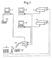
- FIG. 1 a diagram of a network consisting of a central computer and a set of peripheral units; in Fig. 2, an example of a container with an identification code; in Fig. 3, a flow chart representing the method according to the invention in a first embodiment; in Fig. 4, a diagram of a network similar to that of Fig. 1, in a second embodiment; and in Fig. 5, a flow chart representing the method according to the invention in a second embodiment.
- Fig. 1 shows schematically a network of units forming a data processing system in which the method according to the present invention can be implemented.
- the number 1 indicates a central electronic computer (host computer).
- the central computer 1 is programmed to acquire the patient data and to generate for each patient a patient code CP, which for example is printed in the form of a bar code on a paper medium.
- the numbers 3 and 5 indicate two peripheral electronic computers for monitoring and operating corresponding analyzers 7 and 9.
- the patient whose data have been acquired by the central computer 1 and for whom a patient code CP has been output passes into an area for taking biological specimens, showing his patient code CP, and here an operator takes the specimen and places, for example, the blood (or other biological specimen) in one or more containers 13.
- Each container 13 is provided with an identification code Cl, which is unique and absolute, in other words different for each container 13, for example a bar code printed on a self-adhesive label applied to the container 13 during the production of the container.
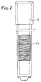
- FIG. 2 An example of a container in the form of a test tube for ESR (erythrocyte sedimentation rate) analysis with its corresponding identification code Cl is shown in detail in Fig. 2.
- ESR erythrocyte sedimentation rate
- an optical reader wand or other equivalent reading device indicated schematically by 15, the operator who takes the specimen, or his assistant, reads the patient code CP and the identification codes Cl of the containers 13 which have to be used for this patient.
- the number 17 indicates a generic control unit of the reader 15 which acquires the codes CP and Cl.
- the unit 15 can be programmed to permit the acquisition of a patient code and an unlimited number (or a number limited to a maximum) of identification codes relating to the same number of other containers.
- Software can be used to ensure that it is not possible to read, for example, two patient codes consecutively, in order to prevent errors, and/or that it is not possible to acquire a patient code after the acquisition of a preceding patient code and one or more identification codes Cl without the execution of a reset operation.
- each patient code CP will be associated in the data processing system with one or more identification codes Cl, relating to the containers in which the operator has placed the patient's biological specimens.
- the data read by the unit 17 are sent to the computers 3 and 5 by means of a data line or other suitable means, if necessary by physically transferring a storage medium such as a diskette or other.
- the specimens in the containers 13 are transferred physically to the analyzers 7, 9 (as shown by the arrowed broken lines).
- the analyzers 7 and 9 comprise corresponding readers (not shown) which read the identification codes Cl of the containers 13 placed in them and carry out the specified analyses. Since each type of analysis frequently requires a specific type of container, it is possible to make the identification code Cl of the individual container contain additional data relating to the type of analysis for which it is intended. For example, specific containers in which a special reagent is kept can be provided for specific clinical chemical analyses, the type of reagent (and therefore the type of analysis) being indicated by one or more digits of the identification code. At the same time, to enable the operator to easily identify the type of container, containers for different analyses can be distinguished by different shapes, or caps of a particular color for each type of container.
- the analyzer receiving a container holding the biological liquid to be analyzed can check, by reading the identification code Cl, that the type of analysis for which the container is intended corresponds to the analysis which the analyzer is to carry out, and can emit an error signal when this is not the case.
- the central computer 1 generates a job sheet where the patient code and the type of analysis to be carried out is shown for each registered patient. These data are then entered by an operator by means of a keyboard into the individual analyzers or into the computers controlling them. Any errors at this point do not cause particular problems, being limited to the possible performance of analyses which were not requested or the omission of analyses which were requested. However, there is no possibility of the occurrence of errors of incorrect combination of the patient data with the results of the analysis.
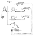
- the analyzers 7 and 9 carry out the requested analyses under the control of the computers 3, 5, and send to the computers 3, 5 the results of the analyses combined with the identification codes Cl read from the individual containers 13. These data are then sent to the unit 17 (or another unit which stores the combination of the code CP and the codes CI generated by the unit 17 by the reading of the codes).
- the unit 17 is connected to the central computer 1 and supplies it with the results of the analysis after it has recombined these with the patient codes on the basis of its knowledge of the correct combination of the identification codes Cl (combined with the results of the analyses obtained from the computers 3, 5) and the patient codes CP.
- the central computer 1 can thus receive the results in the conventional standard format at its input, and does not require reprogramming to execute the described method.
- Fig. 3 summarizes the procedure described above, in the form of a flow chart.
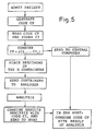
- the system for implementing the method according to the present invention can be simplified as shown in the diagram in Fig. 4, where identical or equivalent parts are indicated by the same reference numbers.
- This diagram additionally shows an analyzer 8 controlled directly by the central computer 1.
- the unit 17 is connected directly to the central computer rather than to the peripheral computers 3 and 5.
- the codes Cl combined with each individual code CP read by the reader 15 are thus communicated by the unit 17 to the central computer 1.
- This computer receives the results of the analyses, combined with the corresponding identification codes Cl of the containers 13 either by the analyzers directly (in the case of the analyzer 8) or by the peripheral computers 3, 5 which control the analyzers (in the case of the analyzers 7 and 9).
- the central computer 1 is programmed so that it can recombine the results of the analyses with the corresponding patient codes CP and then print the results in clear text, by means of the combination communicated by the unit 17.
Landscapes
- Health & Medical Sciences (AREA)
- Engineering & Computer Science (AREA)
- Epidemiology (AREA)
- General Health & Medical Sciences (AREA)
- Medical Informatics (AREA)
- Primary Health Care (AREA)
- Public Health (AREA)
- Automatic Analysis And Handling Materials Therefor (AREA)
- Investigating Or Analysing Biological Materials (AREA)
Claims (16)
- Verfahren für das Datenmanagement in einem Analyselabor, wobei das Verfahren die folgenden Schritte umfasst:• Bereitstellen mehrerer Behälter für die Laboranalyse biologischer Proben, wobei jedem Behälter ein eindeutiger Kennungscode zugeordnet ist, der zur Zeit seiner Herstellung oder Verpackung an dem Behälter platziert wird;• Zuordnen eines Patientencodes zu einem Patienten, der einer Analyse unterzogen werden soll, mittels eines Zentralcomputers;• Erzeugen einer Kombination des Patientencodes und des Kennungscodes des entsprechenden Behälters für jeden Behälter, der für den Patienten verwendet wird, in einem Datenverarbeitungssystem;• Ausführen wenigstens einer Analyse an dem Behälter, der für den Patienten verwendet wird, bzw. an den Behältern, die für den Patienten verwendet werden, mittels wenigstens eines Analysegeräts,wobei das Analysegerät die Ergebnisse der Analyse in Kombination mit dem Kennungscode des Behälters oder der Behälter in das Datenverarbeitungssystem eingibt;
wobei der Kennungscode zusätzliche Daten enthält, die sich auf den Typ der Analyse beziehen, für den der Behälter vorgesehen ist, und wobei das Analysegerät, das einen Behälter empfängt, den Kennungscode liest und prüft, dass der Typ der Analyse, für den der Behälter vorgesehen ist, der Analyse entspricht, die das Analysegerät ausführen soll. - Verfahren nach Anspruch 1, das die folgenden Schritte umfasst:• Erzeugen eines Patientencodes für wenigstens einen Patienten, an dem wenigstens eine Analyse ausgeführt werden soll, und Speichern des Patientencodes in einem Datenverarbeitungssystem;• Platzieren einer biologischen Probe von dem Patienten in den wenigstens einen Behälter;• Ausführen wenigstens einer Analyse der Probe in wenigstens einem Analysegerät, wobei das Analysegerät den Kennungscode des Behälters liest und die Ergebnisse der Analyse in Kombination mit dem Kennungscode des Behälters in das Datenverarbeitungssystem eingibt;• Verwenden des Datenverarbeitungssystems, um die Ergebnisse der Analyse oder der Analysen mittels der Kombination des Patientencodes mit dem Kennungscode dem Patientencode und daraufhin dem durch den Patientencode identifizierten Patienten zuzuordnen.
- Verfahren nach Anspruch 1 oder 2, in dem der Kennungscode in einem maschinenlesbaren Format an dem entsprechenden Behälter platziert wird.
- Verfahren nach Anspruch 1, 2 oder 3, in dem der Patientencode in einem maschinenlesbaren Format auf einem computerlesbaren Medium gespeichert wird.
- Verfahren nach den Ansprüchen 3 und 4, das die folgenden Schritte enthält:Aufeinanderfolgendes Lesen des Patientencodes und des Kennungscodes oder umgekehrt mittels eines automatischen Leseinstruments; Erzeugen der Kombination des Patientencodes und des Kennungscodes durch Kombinieren der aufeinanderfolgend gelesenen Codes.
- Verfahren nach einem oder mehreren der Ansprüche 1 bis 5, in dem der Patientencode und der Kennungscode die Form von Strichcodes haben und optisch gelesen werden.
- Verfahren nach einem oder mehreren der Ansprüche 1 bis 6, in dem der Patientencode durch einen Zentralcomputer des Datenverarbeitungssystems erzeugt wird; wobei die Kombination des Patientencodes mit dem Kennungscode mittels einer anderen Einheit des Datenverarbeitungssystems als dem Zentralcomputer ausgeführt wird; und wobei das Ergebnis der Analyse, dem der Patientencode zugeordnet worden ist, an den Zentralcomputer gesendet wird.
- Verfahren nach einem oder mehreren der Ansprüche 1 bis 6, in dem der Patientencode durch einen Zentralcomputer des Datenverarbeitungssystems erzeugt wird; wobei die Kombination des Patientencodes mit dem Kennungscode mittels einer anderen Einheit des Datenverarbeitungssystems als dem Zentralcomputer ausgeführt wird; und wobei das Ergebnis der Analyse, dem der Kennungscode der Behälter zugeordnet worden ist, an den Zentralcomputer gesendet wird; wobei das Ergebnis der Analyse in dem Zentralcomputer den Daten zugeordnet wird, die sich auf den Patienten beziehen, auf den sich das Ergebnis bezieht.
- Verfahren nach einem der vorangehenden Ansprüche, das den Schritt des Anbringens von Mitteln zum Bestimmen eines Verfallsdatums an den Behältern enthält.
- Verfahren nach einem der vorangehenden Ansprüche, in dem eine in einem Mutterreagenzglas enthaltene Probe auf mehrere Tochterreagenzgläser verteilt wird und jedes Tochterreagenzglas mit einem Kennungscode versehen wird, der zur Zeit seiner Herstellung oder Verpackung an dem Behälter platziert worden ist; wobei das Verfahren die folgenden Schritte enthält: Lesen des Kennungscodes des Mutterreagenzglases und der Kennungscodes der Tochterreagenzgläser und Erzeugen einer Kombination des Kennungscodes jedes Tochterreagenzglases mit dem Kennungscode des Mutterreagenzglases; Ausführen der Analyse an den Tochterreagenzgläsern; Kombinieren der Ergebnisse der Analysen an den Tochterreagenzgläsern mit den Kennungscodes der Tochterreagenzgläser.
- Verfahren nach einem oder mehreren der vorangehenden Ansprüche, das die folgenden Schritte enthält: Bereitstellen einer Verbindung zwischen dem Zentralcomputer und den Peripheriecomputern, die den einzelnen Analysegeräten zugeordnet sind; Liefern von Daten, die sich auf die Typen der Analyse beziehen, die an den einzelnen Patienten ausgeführt werden soll, direkt von dem Zentralcomputer an die Peripheriecomputer.
- Datenverarbeitungssystem für das Datenmanagement in einem Analyselabor, wobei das Datenverarbeitungssystem in Kombination umfasst:• einen elektronischen Zentralcomputer zum Erfassen der Daten über Patienten, an deren biologischen Proben die Analysen ausgeführt werden sollen, und zum Erzeugen eines Patientencodes für jeden erfassten Patienten;• Mittel zum Erfassen eines eindeutigen Kennungscodes, der jedem Behälter mehrerer Behälter für die Laboranalyse biologischer Proben zugeordnet ist, wobei der Kennungscode an dem Behälter während der Herstellung oder Verpackung des Behälters angebracht wird;• Mittel zum Kombinieren jedes der erfassten Kennungscodes mit einem entsprechenden Patientencode;• wenigstens ein Analysegerät mit Mitteln zum Lesen von Kennungscodes, die den Behältern zugeordnet sind, die in ihm platziert sind, wobei das Analysegerät an einer biologischen Probe, die in den Behältern enthalten ist, die in ihm platziert sind, wenigstens eine Analyse ausführt und das Ergebnis der ausgeführten Analysen in Kombination mit Daten, die das Ergebnis dem Patienten zuordnen können, zu dem die biologische Probe gehört, an den elektronischen Computer liefert;wobei der Kennungscode zusätzliche Daten enthält, die sich auf den Typ der Analyse beziehen, für den der Behälter vorgesehen ist, und wobei das Analysegerät, das einen Behälter empfängt, den Kennungscode lesen kann und prüfen kann, dass der Typ der Analyse, für den der Behälter vorgesehen ist, der Analyse entspricht, die das Analysegerät ausführen soll.
- System nach Anspruch 12, das Mittel zum Empfangen des Ergebnisses der wenigstens einen Analyse in Kombination mit dem Kennungscode des Behälters, in dem die analysierte biologische Probe platziert ist, von dem wenigstens einen Analysegerät umfasst, wobei die Mittel das Ergebnis dem Patientencode zuordnen können, der sich auf den Kennungscode bezieht, der mit dem Ergebnis der Analyse in Kombination ist, um das Ergebnis der Analyse in Kombination mit dem Patientencode an den elektronischen Zentralcomputer zu senden.
- System nach Anspruch 12, in dem der Zentralcomputer das Ergebnis der Analyse in Kombination mit dem Kennungscode des entsprechenden Behälters empfangen kann, wobei der Zentralcomputer jeden Kennungscode - und folglich das Ergebnis der Analyse - mittels der Kombination des Patientencodes mit dem Kennungscode dem Patientencode des Patienten zuordnen kann, dessen biologische Probe in dem durch den Kennungscode identifizierten Behälter enthalten ist.
- System nach einem der Ansprüche 12 bis 14, in dem jeder Behälter Mittel zum Bestimmen eines Verfallsdatums enthält
- System nach einem oder mehreren der Ansprüche 12 bis 15, in dem eine Verbindung zwischen dem Zentralcomputer und den Peripheriecomputern, die den einzelnen Analysegeräten zugeordnet sind, bereitgestellt ist; und in dem der Zentralcomputer Daten, die sich auf die Typen der Analyse beziehen, die an den einzelnen Patienten ausgeführt werden soll, direkt an die Peripheriecomputer liefern kann.
Priority Applications (1)
| Application Number | Priority Date | Filing Date | Title |
|---|---|---|---|
| EP06021648A EP1755057A1 (de) | 1999-09-15 | 2000-09-12 | Verfahren und System zur Datenverwaltung in einem Labor |
Applications Claiming Priority (3)
| Application Number | Priority Date | Filing Date | Title |
|---|---|---|---|
| ITFI990191 | 1999-09-15 | ||
| IT1999FI000191A IT1310317B1 (it) | 1999-09-15 | 1999-09-15 | Metodo e mezzi per la gestione di dati in un laboratorio |
| PCT/IT2000/000359 WO2001020532A2 (en) | 1999-09-15 | 2000-09-12 | Method and means for data management in a laboratory |
Related Child Applications (1)
| Application Number | Title | Priority Date | Filing Date |
|---|---|---|---|
| EP06021648A Division EP1755057A1 (de) | 1999-09-15 | 2000-09-12 | Verfahren und System zur Datenverwaltung in einem Labor |
Publications (2)
| Publication Number | Publication Date |
|---|---|
| EP1226539A2 EP1226539A2 (de) | 2002-07-31 |
| EP1226539B1 true EP1226539B1 (de) | 2006-11-29 |
Family
ID=11353069
Family Applications (2)
| Application Number | Title | Priority Date | Filing Date |
|---|---|---|---|
| EP06021648A Ceased EP1755057A1 (de) | 1999-09-15 | 2000-09-12 | Verfahren und System zur Datenverwaltung in einem Labor |
| EP00964617A Expired - Lifetime EP1226539B1 (de) | 1999-09-15 | 2000-09-12 | Verfahren und anlage zur datenverwaltung in einem labor |
Family Applications Before (1)
| Application Number | Title | Priority Date | Filing Date |
|---|---|---|---|
| EP06021648A Ceased EP1755057A1 (de) | 1999-09-15 | 2000-09-12 | Verfahren und System zur Datenverwaltung in einem Labor |
Country Status (11)
| Country | Link |
|---|---|
| US (1) | US6832722B1 (de) |
| EP (2) | EP1755057A1 (de) |
| JP (1) | JP2003509699A (de) |
| AT (1) | ATE347144T1 (de) |
| AU (1) | AU7553800A (de) |
| CA (1) | CA2384845C (de) |
| DE (1) | DE60032165T2 (de) |
| DK (1) | DK1226539T3 (de) |
| ES (1) | ES2277596T3 (de) |
| IT (1) | IT1310317B1 (de) |
| WO (1) | WO2001020532A2 (de) |
Families Citing this family (21)
| Publication number | Priority date | Publication date | Assignee | Title |
|---|---|---|---|---|
| IT1310317B1 (it) * | 1999-09-15 | 2002-02-11 | Diesse Diagnostica Senese Spa | Metodo e mezzi per la gestione di dati in un laboratorio |
| CA2350349A1 (en) * | 2000-08-30 | 2002-02-28 | Wardlaw Partners Lp | Quality control method and apparatus for automated analyses of biologic matter |
| US20030078805A1 (en) * | 2001-04-28 | 2003-04-24 | Baxter International Inc. | A system and method for managing a procedure in a blood component collection facility |
| US7050933B2 (en) * | 2001-08-24 | 2006-05-23 | Bio-Rad Laboratories, Inc. | Biometric quality control process |
| AT413791B (de) * | 2001-09-05 | 2006-06-15 | Ams Engineering Sticht Ges M B | Verfahren zur erstellung eines auftragsdatensatzes für eine zu analysierende probe |
| AT413640B (de) * | 2001-09-05 | 2006-04-15 | Ams Engineering Sticht Ges M B | Verfahren zur entnahme einer probe aus einem system |
| US7125722B2 (en) | 2002-07-03 | 2006-10-24 | Abbott Laboratories | Apparatus and method for handling fluids for analysis |
| US7309010B2 (en) * | 2002-11-04 | 2007-12-18 | Western Pathology Consultants, Inc. | Identification method and apparatus |
| US7860727B2 (en) | 2003-07-17 | 2010-12-28 | Ventana Medical Systems, Inc. | Laboratory instrumentation information management and control network |
| US8719053B2 (en) | 2003-07-17 | 2014-05-06 | Ventana Medical Systems, Inc. | Laboratory instrumentation information management and control network |
| US7278328B2 (en) * | 2004-09-03 | 2007-10-09 | Protedyne Corporation | Method and apparatus for handling sample holders |
| FR2894027B1 (fr) * | 2005-11-25 | 2008-02-29 | Nicolas Bara | Procede securise de prelevement et d'analyse d'echantillons |
| SE529536C2 (sv) * | 2006-01-25 | 2007-09-04 | Hemocue Ab | Metod för säkerställande av en provbehållares kvalitet |
| WO2008111054A2 (en) * | 2007-03-12 | 2008-09-18 | In-Dot Ltd. | A reader device having various functionalities |
| US9075030B2 (en) * | 2008-05-22 | 2015-07-07 | Hitachi High-Technologies Corporation | Automatic analyzer |
| EP2160979A1 (de) * | 2008-09-09 | 2010-03-10 | Roche Diagnostics GmbH | Individualisierung von medizinischen Hilfsmitteln |
| AT512011A2 (de) * | 2011-10-12 | 2013-04-15 | Greiner Bio One Gmbh | Probenentnahmeverfahren zur verwechslungssicheren durchführung einer probenentnahme |
| KR101282662B1 (ko) * | 2012-10-31 | 2013-07-12 | 켐코코리아 주식회사 | 생물학적 자원 저장 관리 방법 |
| GB201314103D0 (en) | 2013-08-07 | 2013-09-18 | Pyramid Innovation | Histological Sample Tracking System |
| CN106384322A (zh) * | 2016-10-07 | 2017-02-08 | 王勇 | 采血袋与样本管对应关系的管理方法 |
| EP3410386A1 (de) | 2017-05-31 | 2018-12-05 | Greiner Bio-One GmbH | Verfahren zum verwalten von daten im gesundheitsbereich |
Family Cites Families (17)
| Publication number | Priority date | Publication date | Assignee | Title |
|---|---|---|---|---|
| US3831006A (en) | 1973-01-19 | 1974-08-20 | Honeywell Inc | Patient-specimen identification system using stored associated numbers |
| US4678894A (en) * | 1985-04-18 | 1987-07-07 | Baxter Travenol Laboratories, Inc. | Sample identification system |
| US4857713A (en) * | 1986-02-14 | 1989-08-15 | Brown Jack D | Hospital error avoidance system |
| US5164575A (en) * | 1991-04-23 | 1992-11-17 | Neeley William E | Blood sampling procedure and apparatus |
| CA2100275A1 (en) * | 1992-07-22 | 1994-01-23 | Mitchell K. Antoon, Jr. | Blood collection assembly |
| DE69416826T2 (de) * | 1993-02-17 | 1999-10-14 | Oxoid Ltd. | Apparat und Verfahren zur Überwachung des Wachstums von Mikroorganismen in Nährbehältern |
| JPH0821839A (ja) * | 1994-07-07 | 1996-01-23 | Hitachi Ltd | 自動分析装置の検体種識別方法 |
| AU3096795A (en) * | 1994-07-11 | 1996-02-09 | Akzo Nobel N.V. | Micro sample tube with reduced dead volume and bar code capability |
| US5735387A (en) * | 1995-07-14 | 1998-04-07 | Chiron Diagnostics Corporation | Specimen rack handling system |
| US5663545A (en) * | 1995-08-23 | 1997-09-02 | Ljl Biosystems Inc. | Labware identification system |
| JPH0972916A (ja) * | 1995-09-05 | 1997-03-18 | Hitachi Ltd | 自動分析装置による検体の検査方法 |
| US5842179A (en) * | 1996-01-22 | 1998-11-24 | Venturedyne Limited | Method and apparatus for inventorying laboratory specimens |
| EP0819470B1 (de) * | 1996-07-18 | 2004-04-28 | Techno Medica Co., Ltd. | Automatische Vorrichtung zum Aufbringen von strichkodierten Etiketten auf Probenröhrchen |
| US6141602A (en) * | 1997-09-25 | 2000-10-31 | Hitachi, Ltd. | Specimen processing system |
| DE19806049A1 (de) * | 1998-02-13 | 1999-08-19 | Bodenseewerk Perkin Elmer Co | Verfahren zur Kennzeichnung von Probenbehältern |
| US6428640B1 (en) * | 1998-08-13 | 2002-08-06 | Becton, Dickinson And Company | Label system and method for label alignment and placement |
| IT1310317B1 (it) * | 1999-09-15 | 2002-02-11 | Diesse Diagnostica Senese Spa | Metodo e mezzi per la gestione di dati in un laboratorio |
-
1999
- 1999-09-15 IT IT1999FI000191A patent/IT1310317B1/it active
-
2000
- 2000-09-12 JP JP2001524040A patent/JP2003509699A/ja active Pending
- 2000-09-12 DK DK00964617T patent/DK1226539T3/da active
- 2000-09-12 US US10/088,320 patent/US6832722B1/en not_active Expired - Lifetime
- 2000-09-12 AT AT00964617T patent/ATE347144T1/de active
- 2000-09-12 AU AU75538/00A patent/AU7553800A/en not_active Abandoned
- 2000-09-12 WO PCT/IT2000/000359 patent/WO2001020532A2/en not_active Ceased
- 2000-09-12 DE DE60032165T patent/DE60032165T2/de not_active Expired - Lifetime
- 2000-09-12 CA CA2384845A patent/CA2384845C/en not_active Expired - Fee Related
- 2000-09-12 EP EP06021648A patent/EP1755057A1/de not_active Ceased
- 2000-09-12 ES ES00964617T patent/ES2277596T3/es not_active Expired - Lifetime
- 2000-09-12 EP EP00964617A patent/EP1226539B1/de not_active Expired - Lifetime
Also Published As
| Publication number | Publication date |
|---|---|
| WO2001020532A2 (en) | 2001-03-22 |
| JP2003509699A (ja) | 2003-03-11 |
| CA2384845A1 (en) | 2001-03-22 |
| ES2277596T3 (es) | 2007-07-16 |
| EP1226539A2 (de) | 2002-07-31 |
| EP1755057A1 (de) | 2007-02-21 |
| IT1310317B1 (it) | 2002-02-11 |
| ITFI990191A1 (it) | 2001-03-15 |
| WO2001020532A3 (en) | 2002-04-11 |
| AU7553800A (en) | 2001-04-17 |
| DK1226539T3 (da) | 2007-04-02 |
| ITFI990191A0 (it) | 1999-09-15 |
| DE60032165T2 (de) | 2007-10-04 |
| CA2384845C (en) | 2010-03-30 |
| DE60032165D1 (de) | 2007-01-11 |
| US6832722B1 (en) | 2004-12-21 |
| ATE347144T1 (de) | 2006-12-15 |
Similar Documents
| Publication | Publication Date | Title |
|---|---|---|
| EP1226539B1 (de) | Verfahren und anlage zur datenverwaltung in einem labor | |
| KR100248364B1 (ko) | 소정의 환자와 의료용 용기를 임시 및 영구 결합하기 위한 방법 및 장치 | |
| US5963368A (en) | Specimen management system | |
| US10228311B2 (en) | Automated lean methods in anatomical pathology | |
| US5164575A (en) | Blood sampling procedure and apparatus | |
| CA2093393A1 (en) | Method and apparatus for labelling and tracking medical specimens | |
| EP1880222B1 (de) | System und vorrichtung zur identifizierung von gewebeproben | |
| EP2116852A2 (de) | Automatisches Analysengerät | |
| JPWO2018051672A1 (ja) | 自動分析装置および自動分析システム並びに試薬リストの表示方法 | |
| US4460824A (en) | Test requisition card for automatic analyzing apparatus | |
| CN101720469A (zh) | 用于识别患者以及标记所述患者生物样本容器的装置和方法 | |
| EP3538051A1 (de) | Probenahmekit zur identifizierung positiver proben | |
| US20140337056A1 (en) | Sampling method for performing sampling in an unmistakeable manner | |
| JP4413115B2 (ja) | 検体情報管理装置および検体情報管理方法 | |
| JP2584009Y2 (ja) | 血液容器の仕分け装置 | |
| JP7410426B2 (ja) | ラベル管理システム | |
| JP2003294764A (ja) | 検体取扱システム | |
| JPH0821838A (ja) | 検査システムにおける検査指示装置 | |
| JPH04256855A (ja) | 検体の処理経過記録装置 | |
| EP0551101A2 (de) | Verfahren zur Eingabe von Strichkodes für Computerbetrieb | |
| Whitehead | Symposium on automation and data processing in pathology. Preface | |
| AU716069B2 (en) | Blood processing system | |
| Keller | Computers in the modern clinical laboratory: interfacing and sample identification | |
| Vitek et al. | An Off-Line Clinical Chemistry Computer System | |
| Ohlsén et al. | The History of the Data Systems AutoChemist®(ACH) and AutoChemist-PRISMA (PRISMA®): from 1964 to 1986 |
Legal Events
| Date | Code | Title | Description |
|---|---|---|---|
| PUAI | Public reference made under article 153(3) epc to a published international application that has entered the european phase |
Free format text: ORIGINAL CODE: 0009012 |
|
| 17P | Request for examination filed |
Effective date: 20020408 |
|
| AK | Designated contracting states |
Kind code of ref document: A2 Designated state(s): AT BE CH CY DE DK ES FI FR GB GR IE IT LI LU MC NL PT SE |
|
| AX | Request for extension of the european patent |
Free format text: AL;LT;LV;MK;RO;SI |
|
| 17Q | First examination report despatched |
Effective date: 20040308 |
|
| GRAP | Despatch of communication of intention to grant a patent |
Free format text: ORIGINAL CODE: EPIDOSNIGR1 |
|
| GRAS | Grant fee paid |
Free format text: ORIGINAL CODE: EPIDOSNIGR3 |
|
| GRAA | (expected) grant |
Free format text: ORIGINAL CODE: 0009210 |
|
| AK | Designated contracting states |
Kind code of ref document: B1 Designated state(s): AT BE CH CY DE DK ES FI FR GB GR IE IT LI LU MC NL PT SE |
|
| PG25 | Lapsed in a contracting state [announced via postgrant information from national office to epo] |
Ref country code: FI Free format text: LAPSE BECAUSE OF FAILURE TO SUBMIT A TRANSLATION OF THE DESCRIPTION OR TO PAY THE FEE WITHIN THE PRESCRIBED TIME-LIMIT Effective date: 20061129 |
|
| REG | Reference to a national code |
Ref country code: GB Ref legal event code: FG4D |
|
| REG | Reference to a national code |
Ref country code: CH Ref legal event code: EP |
|
| REG | Reference to a national code |
Ref country code: IE Ref legal event code: FG4D |
|
| REF | Corresponds to: |
Ref document number: 60032165 Country of ref document: DE Date of ref document: 20070111 Kind code of ref document: P |
|
| PG25 | Lapsed in a contracting state [announced via postgrant information from national office to epo] |
Ref country code: SE Free format text: LAPSE BECAUSE OF FAILURE TO SUBMIT A TRANSLATION OF THE DESCRIPTION OR TO PAY THE FEE WITHIN THE PRESCRIBED TIME-LIMIT Effective date: 20070228 |
|
| REG | Reference to a national code |
Ref country code: CH Ref legal event code: NV Representative=s name: KIRKER & CIE SA |
|
| REG | Reference to a national code |
Ref country code: GR Ref legal event code: EP Ref document number: 20070400564 Country of ref document: GR |
|
| REG | Reference to a national code |
Ref country code: DK Ref legal event code: T3 |
|
| PG25 | Lapsed in a contracting state [announced via postgrant information from national office to epo] |
Ref country code: PT Free format text: LAPSE BECAUSE OF FAILURE TO SUBMIT A TRANSLATION OF THE DESCRIPTION OR TO PAY THE FEE WITHIN THE PRESCRIBED TIME-LIMIT Effective date: 20070430 |
|
| ET | Fr: translation filed | ||
| REG | Reference to a national code |
Ref country code: ES Ref legal event code: FG2A Ref document number: 2277596 Country of ref document: ES Kind code of ref document: T3 |
|
| PLBI | Opposition filed |
Free format text: ORIGINAL CODE: 0009260 |
|
| PLAX | Notice of opposition and request to file observation + time limit sent |
Free format text: ORIGINAL CODE: EPIDOSNOBS2 |
|
| 26 | Opposition filed |
Opponent name: ORGENTEC DIAGNOSTIKA GMBH Effective date: 20070828 |
|
| NLR1 | Nl: opposition has been filed with the epo |
Opponent name: ORGENTEC DIAGNOSTIKA GMBH |
|
| PLAF | Information modified related to communication of a notice of opposition and request to file observations + time limit |
Free format text: ORIGINAL CODE: EPIDOSCOBS2 |
|
| PLBB | Reply of patent proprietor to notice(s) of opposition received |
Free format text: ORIGINAL CODE: EPIDOSNOBS3 |
|
| PG25 | Lapsed in a contracting state [announced via postgrant information from national office to epo] |
Ref country code: MC Free format text: LAPSE BECAUSE OF NON-PAYMENT OF DUE FEES Effective date: 20070930 |
|
| PG25 | Lapsed in a contracting state [announced via postgrant information from national office to epo] |
Ref country code: LU Free format text: LAPSE BECAUSE OF NON-PAYMENT OF DUE FEES Effective date: 20070912 Ref country code: CY Free format text: LAPSE BECAUSE OF FAILURE TO SUBMIT A TRANSLATION OF THE DESCRIPTION OR TO PAY THE FEE WITHIN THE PRESCRIBED TIME-LIMIT Effective date: 20061129 |
|
| RDAF | Communication despatched that patent is revoked |
Free format text: ORIGINAL CODE: EPIDOSNREV1 |
|
| APBM | Appeal reference recorded |
Free format text: ORIGINAL CODE: EPIDOSNREFNO |
|
| APBP | Date of receipt of notice of appeal recorded |
Free format text: ORIGINAL CODE: EPIDOSNNOA2O |
|
| APAH | Appeal reference modified |
Free format text: ORIGINAL CODE: EPIDOSCREFNO |
|
| APBQ | Date of receipt of statement of grounds of appeal recorded |
Free format text: ORIGINAL CODE: EPIDOSNNOA3O |
|
| REG | Reference to a national code |
Ref country code: FR Ref legal event code: PLFP Year of fee payment: 16 |
|
| REG | Reference to a national code |
Ref country code: DE Ref legal event code: R100 Ref document number: 60032165 Country of ref document: DE |
|
| APBU | Appeal procedure closed |
Free format text: ORIGINAL CODE: EPIDOSNNOA9O |
|
| REG | Reference to a national code |
Ref country code: FR Ref legal event code: PLFP Year of fee payment: 17 |
|
| PLCK | Communication despatched that opposition was rejected |
Free format text: ORIGINAL CODE: EPIDOSNREJ1 |
|
| PLBN | Opposition rejected |
Free format text: ORIGINAL CODE: 0009273 |
|
| 27O | Opposition rejected |
Effective date: 20160927 |
|
| REG | Reference to a national code |
Ref country code: FR Ref legal event code: PLFP Year of fee payment: 18 |
|
| REG | Reference to a national code |
Ref country code: FR Ref legal event code: PLFP Year of fee payment: 19 |
|
| PGFP | Annual fee paid to national office [announced via postgrant information from national office to epo] |
Ref country code: IE Payment date: 20180628 Year of fee payment: 19 |
|
| PGFP | Annual fee paid to national office [announced via postgrant information from national office to epo] |
Ref country code: FR Payment date: 20180628 Year of fee payment: 19 |
|
| PGFP | Annual fee paid to national office [announced via postgrant information from national office to epo] |
Ref country code: IT Payment date: 20180629 Year of fee payment: 19 Ref country code: DE Payment date: 20180905 Year of fee payment: 19 |
|
| REG | Reference to a national code |
Ref country code: DE Ref legal event code: R079 Ref document number: 60032165 Country of ref document: DE Free format text: PREVIOUS MAIN CLASS: G06F0019000000 Ipc: G16Z0099000000 |
|
| PGFP | Annual fee paid to national office [announced via postgrant information from national office to epo] |
Ref country code: GB Payment date: 20180912 Year of fee payment: 19 Ref country code: BE Payment date: 20180827 Year of fee payment: 19 Ref country code: AT Payment date: 20180918 Year of fee payment: 19 Ref country code: CH Payment date: 20180927 Year of fee payment: 19 Ref country code: NL Payment date: 20180926 Year of fee payment: 19 Ref country code: DK Payment date: 20180816 Year of fee payment: 19 Ref country code: GR Payment date: 20180725 Year of fee payment: 19 |
|
| PGFP | Annual fee paid to national office [announced via postgrant information from national office to epo] |
Ref country code: ES Payment date: 20181011 Year of fee payment: 19 |
|
| REG | Reference to a national code |
Ref country code: DE Ref legal event code: R119 Ref document number: 60032165 Country of ref document: DE |
|
| REG | Reference to a national code |
Ref country code: DK Ref legal event code: EBP Effective date: 20190930 |
|
| REG | Reference to a national code |
Ref country code: NL Ref legal event code: MM Effective date: 20191001 |
|
| REG | Reference to a national code |
Ref country code: CH Ref legal event code: PL |
|
| PG25 | Lapsed in a contracting state [announced via postgrant information from national office to epo] |
Ref country code: CH Free format text: LAPSE BECAUSE OF NON-PAYMENT OF DUE FEES Effective date: 20190930 Ref country code: GR Free format text: LAPSE BECAUSE OF NON-PAYMENT OF DUE FEES Effective date: 20200416 Ref country code: DE Free format text: LAPSE BECAUSE OF NON-PAYMENT OF DUE FEES Effective date: 20200401 Ref country code: LI Free format text: LAPSE BECAUSE OF NON-PAYMENT OF DUE FEES Effective date: 20190930 Ref country code: NL Free format text: LAPSE BECAUSE OF NON-PAYMENT OF DUE FEES Effective date: 20191001 Ref country code: IE Free format text: LAPSE BECAUSE OF NON-PAYMENT OF DUE FEES Effective date: 20190912 |
|
| REG | Reference to a national code |
Ref country code: BE Ref legal event code: MM Effective date: 20190930 |
|
| REG | Reference to a national code |
Ref country code: AT Ref legal event code: MM01 Ref document number: 347144 Country of ref document: AT Kind code of ref document: T Effective date: 20190912 |
|
| PG25 | Lapsed in a contracting state [announced via postgrant information from national office to epo] |
Ref country code: BE Free format text: LAPSE BECAUSE OF NON-PAYMENT OF DUE FEES Effective date: 20190930 Ref country code: IT Free format text: LAPSE BECAUSE OF NON-PAYMENT OF DUE FEES Effective date: 20190912 |
|
| GBPC | Gb: european patent ceased through non-payment of renewal fee |
Effective date: 20190912 |
|
| PG25 | Lapsed in a contracting state [announced via postgrant information from national office to epo] |
Ref country code: GB Free format text: LAPSE BECAUSE OF NON-PAYMENT OF DUE FEES Effective date: 20190912 Ref country code: FR Free format text: LAPSE BECAUSE OF NON-PAYMENT OF DUE FEES Effective date: 20190930 Ref country code: DK Free format text: LAPSE BECAUSE OF NON-PAYMENT OF DUE FEES Effective date: 20190930 |
|
| PG25 | Lapsed in a contracting state [announced via postgrant information from national office to epo] |
Ref country code: AT Free format text: LAPSE BECAUSE OF NON-PAYMENT OF DUE FEES Effective date: 20190912 |
|
| REG | Reference to a national code |
Ref country code: ES Ref legal event code: FD2A Effective date: 20210127 |
|
| PG25 | Lapsed in a contracting state [announced via postgrant information from national office to epo] |
Ref country code: ES Free format text: LAPSE BECAUSE OF NON-PAYMENT OF DUE FEES Effective date: 20190913 |