EP1225044A1 - Bogentransporttrommel - Google Patents
Bogentransporttrommel Download PDFInfo
- Publication number
- EP1225044A1 EP1225044A1 EP02001311A EP02001311A EP1225044A1 EP 1225044 A1 EP1225044 A1 EP 1225044A1 EP 02001311 A EP02001311 A EP 02001311A EP 02001311 A EP02001311 A EP 02001311A EP 1225044 A1 EP1225044 A1 EP 1225044A1
- Authority
- EP
- European Patent Office
- Prior art keywords
- cover
- sheet transport
- transport drum
- sheet
- comb
- Prior art date
- Legal status (The legal status is an assumption and is not a legal conclusion. Google has not performed a legal analysis and makes no representation as to the accuracy of the status listed.)
- Granted
Links
- 238000012546 transfer Methods 0.000 title description 2
- 238000007639 printing Methods 0.000 claims description 21
- 239000000463 material Substances 0.000 claims description 7
- 239000000758 substrate Substances 0.000 description 8
- 238000007789 sealing Methods 0.000 description 3
- 238000004804 winding Methods 0.000 description 3
- 241000124008 Mammalia Species 0.000 description 1
- 238000005452 bending Methods 0.000 description 1
- 230000001419 dependent effect Effects 0.000 description 1
- 238000013461 design Methods 0.000 description 1
- 238000011161 development Methods 0.000 description 1
- 230000018109 developmental process Effects 0.000 description 1
- 238000006073 displacement reaction Methods 0.000 description 1
- 229920001971 elastomer Polymers 0.000 description 1
- 239000000806 elastomer Substances 0.000 description 1
- 239000012530 fluid Substances 0.000 description 1
- 239000011888 foil Substances 0.000 description 1
- 238000003780 insertion Methods 0.000 description 1
- 230000037431 insertion Effects 0.000 description 1
- 238000007726 management method Methods 0.000 description 1
- 238000000034 method Methods 0.000 description 1
- 230000002093 peripheral effect Effects 0.000 description 1
- 229920000728 polyester Polymers 0.000 description 1
Images

Classifications
-
- B—PERFORMING OPERATIONS; TRANSPORTING
- B41—PRINTING; LINING MACHINES; TYPEWRITERS; STAMPS
- B41F—PRINTING MACHINES OR PRESSES
- B41F21/00—Devices for conveying sheets through printing apparatus or machines
- B41F21/10—Combinations of transfer drums and grippers
- B41F21/106—Combinations of transfer drums and grippers for reversing sheets, e.g. for perfecting machine
Definitions
- the invention relates to a sheet transport drum, which is a first Comb segment and a second comb segment, which for adjustment to a Substrate sheet of the appropriate format length relative to the first comb segment is rotatably mounted, in a sheet-fed printing machine, according to the preamble of Claim 1.
- the invention is therefore based on the object of having a sheet transport drum To create comb segments in which the uncontrolled lifting of the substrate sheet is avoided even at very high machine speeds.
- this cover is not identical to the substrate sheet.
- the printing material sheet is the same on the sheet transport drum according to the invention safely guided, as on a sheet transport drum with a closed Circumferential surface or as on an impression cylinder, even at very high Machine speeds of e.g. B. 15,000 or more sheets per hour.
- a first cover and to cover gaps between a second cover can be arranged on the prongs of the second comb segment.
- the at least one cover can be operated pneumatically and / or can be wound up and unwound be trained.
- the cover can be at least on the outside or inside one of the comb segments.
- Sheet transport drum Further constructively and functionally advantageous developments of the invention Sheet transport drum are mentioned in the subclaims and result from the following description of preferred exemplary embodiments and the associated Drawing.
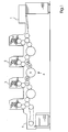
- Figure 1 is a sheet-fed rotary printing press in series with a Sheet feeder 1, printing units 2, 3 for printing substrate sheets according to the Offset method, a turning device 4 arranged between the printing units 2, 3 and a sheet delivery 5 shown.
- Each of the printing units 2, 3 comprises a printing form cylinder, a blanket cylinder and an impression cylinder 6, 7.
- the turning device 4 has three Sheet transport drums 8, 9, 10, which interposed the impression cylinders 6, 7 are.
- the sheet transport drum 9 functions as a so-called storage drum and holds with its gripper system, the printing material sheet is firmly attached to its front edge.
- the Sheet transport drum 10 functions as a so-called turning drum and detects by means of it Gripper system a trailing edge of the substrate sheet to turn it and from deduct the sheet transport drum 9.
- the sheet transport drum 9 is shown in a plan view, which recognize leaves that the sheet transport drum 9 at least a first comb segment 11 and comprises second comb segment 12, which is used to adapt the sheet transport drum 9 to different format lengths of the substrate sheets to be transported by one Pivot axis 13, which corresponds to the central axis of the sheet transport drum 9, relative to first comb segment 11 is rotatably or pivotally mounted.
- Each of the comb segments 11, 12 has tines 14, which in spaces 15 between the tines of each intervene in another comb segment.
- Adjustment of the second to adapt to a smaller sheet format Comb segment 12 to the first comb segment 11 causes a deeper insertion of the Tines 14 in the spaces 15 and thus a narrowing of the spaces 15 and an adjustment of the second to adapt to a larger sheet format Comb segment 12 away from first comb segment 11 has an expansion of the Spaces 15 result.
- the gripper system of the sheet transport drum 9 consists of at the front edge of the first Comb segments 11 arranged gripper pads 16 and grippers 17 associated therewith (cf. FIG. 3) for clamping the printing material sheet.
- On the second comb segment 12 are nozzle-shaped suction cups 18 for sucking up the printing material sheet on its rear edge arranged in a row, which are connected to a suction air source.
- the suction cups 18 For the purpose of setting the required depending on the format length Distance between the gripper system and the suction cups 18 are the latter together with the second comb segment 12 about the pivot axis 13 relative to the gripper system in pivoted a position in which the suction cups 18 close to the rear edge of the Gripper system held substrate and under the latter.
- FIG 3 is a first embodiment of the sheet transport drum 9 in one lateral sectional view shown, according to which at least one cover 19 in hollow interior of the sheet transport drum 9 below the comb segments 11, 12 is arranged.
- the cover 19 lying on the inside against the comb segments 11, 12 covers the spaces 15 as a sealing element and prevents air flows through the spaces 15 through out of the sheet transport drum 9.
- the wall which as an expansion chamber variable in volume, more precisely as a balloon, trained cover 19 consists of a stretchable, flexible material, preferably an elastomer.
- the volume variability can also be achieved by the cover 19 can be designed as an accordion-shaped bellows, whose zigzag-shaped wall has kinks as bending joints.
- the cover 19 is pumped up with air.
- inflatable and the air can later be evacuated again from the cover 19, e.g. B. by pushing or sucking the air out.
- pressurized fluid or gas can be used to fill the cover 19.
- the function of the cover 19 is as follows: As a result of each format changeover Sheet transport drum 9 from a small format length to a large format length, i. H. as a result of any displacement of the second comb segment 12 from the first comb segment 11 away, one of the comb segments 11, 12 and a drum core Sheet transport drum 9 expanded cavity, the cover 19th can fill in.
- the countermeasure taken is to inflate the Cover 19, preferably by means of compressed air, whereby the cover 19 on the one hand in Circumferential direction of the sheet transport drum 9, d. H. in the direction of adjustment of the second Comb segment 12, and on the other hand in the radial direction of the sheet transport drum 9 expanded. Due to the expansion of the cover 19 in the circumferential direction the spaces 15 of the second comb segment 12 are again completely from the Cover 19 closed. The radial expansion of the cover 19 causes the cover 19 to nestle more tightly on the comb segment 12, so that the hermetic sealing of the intermediate spaces 15 is ensured again. That in the Cover 19 enclosed air volume is during or after each Format setting increased from the small format length to the large format length.
- the cover 19 of the second embodiment is the same as that of the first Embodiment by varying their internal pressure and / or their included air volume expandable depending on the format length, but not as one Balloon but designed as an inflatable tube, which in multiple Arrangement, d. H. once per space 15 is provided.
- the tubular cover 19 is guided by a prong-shaped guide 23, which are equidistant from the corresponding space 15 to these Prong 14 delimiting space 15 extends.
- the tubular cover 19 is dependent on the adjustment of the second comb segment 12 Inflating and deflating the air is essentially the same function as the balloon-shaped cover of the first embodiment.
- the tubular cover 19 is during or after inflation a coil 21 attached to the second comb segment 12 can be partially unwound and partially during the deflation or only afterwards again on the coil 21 wound.
- a front end of the tubular cover 19 is at the first Comb segment 11 is attached and a rear end of the cover 19 is on the coil 21 attached so that the cover 19 each time the second comb segment 12 is adjusted is automatically unwound from the coil 21 from the first comb segment 11.
- the Cover 19 and the coil 21 can form a roller blind, the spring of which Unwinding the cover 19 is tensioned and the subsequent winding of the cover 19 drives, the spring relaxes again.
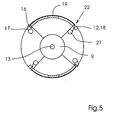
- FIG. 5 shows a third exemplary embodiment, the one with the others Embodiments common and already explained in connection with the latter Parts (reference numerals 11 to 18, 20, 21) not to avoid repetitions be explained again.
- the cover 19 present in the third exemplary embodiment is all of them Tines 14 and spaces 15 of the comb segments 11, 12 covering foil formed which is made of polyester or a similar material, which the Cover 19 gives a certain dimensional stability that is greater than the dimensional stability of the inflatable covers shown in Figures 3 and 4.
- the film-shaped cover 19 is as a cylinder lift on the sheet transport drum 9 stretched so that the cover 19 taut on outer peripheral surfaces of the Comb segments 11, 12 rests and closes the spaces 15 airtight to the afterflow of air through the To prevent gaps 15 through.
- a front end of the to the Comb segments 11, 12 on the outside adjacent film-shaped cover 19 is on first comb segment 11 attached, e.g. B. glued, and a rear end is at the in the Sheet transport drum 9 integrated coil 21 attached, for. B. jammed in the latter.
- the Coil 21 is the same in the third embodiment as in the second Embodiment rotatably attached to the second comb segment 12.
- the film-shaped Cover 19 is through a slot 22 parallel to the pivot axis 13 in the second Comb segment 12, which is still in front of the suction cups 18, below the circumferential contour the sheet transport drum 9 and led to the coil 21 seated inside which the film-shaped cover 19 is partially wound.
- Winding and unwinding of the film-shaped cover 19 is done with the ready explained winding and unwinding of the tubular cover of the second Embodiment comparable way.
Landscapes
- Feeding Of Articles By Means Other Than Belts Or Rollers (AREA)
- Discharge By Other Means (AREA)
- Unwinding Webs (AREA)
- Discharging, Photosensitive Material Shape In Electrophotography (AREA)
- Making Paper Articles (AREA)
- Delivering By Means Of Belts And Rollers (AREA)
- Photoreceptors In Electrophotography (AREA)
Abstract
Description
- Figur 1
- eine Bogenrotationsdruckmaschine mit einer Wendeeinrichtung,
- Figur 2
- eine Bogentransporttrommel der Wendeeinrichtung und
- Figuren 3 bis 5
- verschiedene Ausführungsbeispiele der Bogentransporttrommel.
- 1
- Bogenanleger
- 2
- Druckwerk
- 3
- Druckwerk
- 4
- Wendeeinrichtung
- 5
- Bogenausleger
- 6
- Gegendruckzylinder
- 7
- Gegendruckzylinder
- 8
- Bogentransporttrommel
- 9
- Bogentransporttrommel (Speichertrommel)
- 10
- Bogentransporttrommel (Wendetrommel)
- 11
- erstes Kammsegment
- 12
- zweites Kammsegment
- 13
- Schwenkachse
- 14
- Zinken
- 15
- Zwischenraum
- 16
- Greiferauflage
- 17
- Greifer
- 18
- Sauger
- 19
- Abdeckung
- 20
- Leitung
- 21
- Spule
- 22
- Schlitz
- 23
- Führung
Claims (11)
- Bogentransporttrommel (9), welche ein erstes Kammsegment (11) und ein zweites Kammsegment (12) umfaßt, das zur Einstellung auf eine einen Bedruckstoffbogen entsprechende Formatlänge relativ zum ersten Kammsegment (11) verdrehbar gelagert ist, in einer Bogendruckmaschine,
dadurch gekennzeichnet, dass Zwischenräume (15) zwischen Zinken (14) der Kammsegmente (11, 12) mittels mindestens einer Abdeckung (19) abgedeckt sind. - Bogentransporttrommel nach Anspruch 1,
dadurch gekennzeichnet, dass die Abdeckung (19) innenseitig an mindestens einem der Kammsegmente (11, 12) anliegt. - Bogentransporttrommel nach Anspruch 1 oder 2,
dadurch gekennzeichnet, dass die Abdeckung (19) pneumatisch betätigbar ausgebildet ist. - Bogentransporttrommel nach Anspruch 3,
dadurch gekennzeichnet, dass die Abdeckung (19) aufblasbar ausgebildet ist. - Bogentransporttrommel nach Anspruch 4,
dadurch gekennzeichnet, dass die Abdeckung (19) ein Schlauch, Balg oder Ballon ist. - Bogentransporttrommel nach Anspruch 1,
dadurch gekennzeichnet, dass die Abdeckung (19) außenseitig an mindestens einem der Kammsegmente (11, 12) anliegt. - Bogentransporttrommel nach Anspruch 1 oder 6,
dadurch gekennzeichnet, dass die Abdeckung (19) eine Folie ist. - Bogentransporttrommel nach einem der Ansprüche 1 bis 7,
dadurch gekennzeichnet, dass die Abdeckung (19) teilweise aufgewickelt ist. - Bogendruckmaschine mit mindestens einer nach einem der Ansprüche 1 bis 8 ausgebildeten Bogentransporttrommel (9).
- Bogendruckmaschine nach Anspruch 9,
dadurch gekennzeichnet, dass diese eine Wendeeinrichtung (4) umfaßt, deren Bestandteil die Bogentransporttrommel (9) ist. - Bogendruckmaschine nach Anspruch 10,
dadurch gekennzeichnet, dass die Wendeeinrichtung (4) zusätzlich zur als Speichertrommel ausgebildeten Bogentransporttrommel (9) eine als Wendetrommel ausgebildete weitere Bogentransporttrommel (10) umfaßt.
Applications Claiming Priority (2)
| Application Number | Priority Date | Filing Date | Title |
|---|---|---|---|
| DE10102226 | 2001-01-19 | ||
| DE10102226A DE10102226A1 (de) | 2001-01-19 | 2001-01-19 | Bogentransporttrommel |
Publications (2)
| Publication Number | Publication Date |
|---|---|
| EP1225044A1 true EP1225044A1 (de) | 2002-07-24 |
| EP1225044B1 EP1225044B1 (de) | 2006-07-26 |
Family
ID=7671025
Family Applications (1)
| Application Number | Title | Priority Date | Filing Date |
|---|---|---|---|
| EP02001311A Expired - Lifetime EP1225044B1 (de) | 2001-01-19 | 2002-01-18 | Bogentransporttrommel |
Country Status (8)
| Country | Link |
|---|---|
| US (1) | US6659456B2 (de) |
| EP (1) | EP1225044B1 (de) |
| JP (1) | JP4574935B2 (de) |
| CN (1) | CN1191164C (de) |
| AT (1) | ATE333994T1 (de) |
| CZ (1) | CZ299680B6 (de) |
| DE (2) | DE10102226A1 (de) |
| HK (1) | HK1048618B (de) |
Families Citing this family (10)
| Publication number | Priority date | Publication date | Assignee | Title |
|---|---|---|---|---|
| DE10122227B4 (de) * | 2001-05-08 | 2012-03-01 | Koenig & Bauer Aktiengesellschaft | Speichertrommel in Wendeeinrichtungen von Bogendruckmaschinen |
| ATE418452T1 (de) * | 2002-10-30 | 2009-01-15 | Heidelberger Druckmasch Ag | Bogentransporttrommel einer bedruckstoffbogen verarbeitenden maschine |
| DE10355045B4 (de) * | 2002-12-20 | 2018-09-06 | Heidelberger Druckmaschinen Ag | Verfahren zur Variation eines Trommelprofils einer Vario-Trommel und Vario-Trommel zur Durchführung des Verfahrens |
| JP5361168B2 (ja) | 2006-11-10 | 2013-12-04 | ハイデルベルガー ドルツクマシーネン アクチエンゲゼルシヤフト | 枚葉紙を印刷機を通して搬送する間に反転させるための装置 |
| DE102007049380B4 (de) * | 2006-11-10 | 2021-03-25 | Heidelberger Druckmaschinen Ag | Vorrichtung zum Wenden eines Bogens während des Förderns durch eine Druckmaschine |
| DE102012218048B4 (de) | 2011-10-14 | 2023-11-30 | Koenig & Bauer Ag | Bogentransporttrommel, Verwendung von wechselbaren Überzügen an jeweiligen Zinken von Mantelsegmenten einer Bogentransporttrommel und Verfahren zum Einstellen von Kontakteigenschaften einer Bogentransporttrommel |
| DE102016205769A1 (de) | 2015-05-06 | 2016-11-10 | Heidelberger Druckmaschinen Ag | Bogentransporttrommel und Druckmaschine mit einer solchen Bogentransporttrommel |
| DE102015211440B3 (de) * | 2015-06-22 | 2016-04-28 | Heidelberger Druckmaschinen Ag | Bogentransporttrommel und Druckmaschine mit einer solchen Bogentransporttrommel |
| DE102016202242A1 (de) | 2016-02-15 | 2016-12-22 | Heidelberger Druckmaschinen Ag | Transportelement für Bogen |
| DE102021105926A1 (de) * | 2021-03-11 | 2022-09-15 | Koenig & Bauer Ag | Transportzylinder, Trocknungseinheit mit diesem Transportzylinder und Bogendruckmaschine mit dieser Trocknungseinheit |
Citations (2)
| Publication number | Priority date | Publication date | Assignee | Title |
|---|---|---|---|---|
| US5172634A (en) * | 1992-06-19 | 1992-12-22 | Shinohara Machinery Co., Ltd. | Intermediate cylinder of sheet-feed press |
| EP0875376A1 (de) * | 1997-04-24 | 1998-11-04 | Komori Corporation | Bogen-Wendeeinrichtung für Bogenrationsdruckmaschinen |
Family Cites Families (6)
| Publication number | Priority date | Publication date | Assignee | Title |
|---|---|---|---|---|
| DE2632243C3 (de) * | 1976-07-17 | 1979-08-30 | Heidelberger Druckmaschinen Ag, 6900 Heidelberg | Auf variable Bogenlängen einstellbare Umführtrommel für Druckmaschinen |
| US4858910A (en) * | 1987-01-22 | 1989-08-22 | M.A.N. Roland Druckmaschinen | Conveyor for a sheet-fed rotary press |
| DE3902923C2 (de) * | 1988-03-16 | 1994-06-01 | Heidelberger Druckmasch Ag | Bogenführungstrommel für Bogenrotationsdruckmaschinen |
| US5685226A (en) * | 1996-02-26 | 1997-11-11 | Presstek, Inc. | Adaptive clamping mechanism for printing plates |
| AU7447998A (en) * | 1998-05-24 | 1999-12-13 | Indigo N.V. | Printing system |
| US6166160A (en) * | 1999-02-04 | 2000-12-26 | The Goodyear Tire & Rubber Company | Process for making deodorized rubbery polymer |
-
2001
- 2001-01-19 DE DE10102226A patent/DE10102226A1/de not_active Withdrawn
- 2001-11-07 CZ CZ20014001A patent/CZ299680B6/cs not_active IP Right Cessation
- 2001-12-27 CN CNB011448784A patent/CN1191164C/zh not_active Expired - Fee Related
-
2002
- 2002-01-10 JP JP2002003594A patent/JP4574935B2/ja not_active Expired - Fee Related
- 2002-01-18 DE DE50207582T patent/DE50207582D1/de not_active Expired - Lifetime
- 2002-01-18 EP EP02001311A patent/EP1225044B1/de not_active Expired - Lifetime
- 2002-01-18 AT AT02001311T patent/ATE333994T1/de not_active IP Right Cessation
- 2002-01-22 US US10/053,971 patent/US6659456B2/en not_active Expired - Fee Related
-
2003
- 2003-02-07 HK HK03100881.9A patent/HK1048618B/zh not_active IP Right Cessation
Patent Citations (2)
| Publication number | Priority date | Publication date | Assignee | Title |
|---|---|---|---|---|
| US5172634A (en) * | 1992-06-19 | 1992-12-22 | Shinohara Machinery Co., Ltd. | Intermediate cylinder of sheet-feed press |
| EP0875376A1 (de) * | 1997-04-24 | 1998-11-04 | Komori Corporation | Bogen-Wendeeinrichtung für Bogenrationsdruckmaschinen |
Also Published As
| Publication number | Publication date |
|---|---|
| DE50207582D1 (de) | 2006-09-07 |
| HK1048618A1 (en) | 2003-04-11 |
| JP2002273852A (ja) | 2002-09-25 |
| CN1191164C (zh) | 2005-03-02 |
| CZ299680B6 (cs) | 2008-10-15 |
| CN1365888A (zh) | 2002-08-28 |
| CZ20014001A3 (cs) | 2002-09-11 |
| ATE333994T1 (de) | 2006-08-15 |
| EP1225044B1 (de) | 2006-07-26 |
| HK1048618B (zh) | 2005-10-07 |
| US6659456B2 (en) | 2003-12-09 |
| DE10102226A1 (de) | 2002-07-25 |
| US20020096825A1 (en) | 2002-07-25 |
| JP4574935B2 (ja) | 2010-11-04 |
Similar Documents
| Publication | Publication Date | Title |
|---|---|---|
| DE2354418C3 (de) | Bogenübergabetrommel für Druckmaschinen | |
| DE1916768C3 (de) | Reifenaufbautrommel | |
| DE2318914C3 (de) | ||
| DE2738566C2 (de) | Bei einer Reifenaufbautrommel zum Umschlagen der Bänder einer Karkassenbahn vorgesehener elastischer, ringförmiger Balg | |
| EP0812686B1 (de) | Verfahren und Vorrichtung zum Aufbringen einer ebenen Druckplatte auf einen fliegend gelagerten Plattenzylinder einer Druckmaschine | |
| EP0527424B1 (de) | Trommel zum Transportieren von Bogen | |
| DE102012207103A1 (de) | Plattenzylinder und ein Verfahren zum Anordnen einer Druckform auf einen Plattenzylinder | |
| EP0680826B1 (de) | Vorrichtung zum Befestigen einer biegsamen Druckplatte | |
| EP2736723A2 (de) | Plattenzylinder | |
| EP1225044B1 (de) | Bogentransporttrommel | |
| DD297368A5 (de) | Zugwalzeneinheit zum transport einer papierbahn in einer rollendruckmaschine | |
| EP2726292A1 (de) | Verfahren zum anordnen einer druckplatte auf einem plattenzylinder | |
| DE4214207C1 (de) | ||
| DE1900160B2 (de) | Vorrichtung zum haltern einer materialrolle an einer material bahnen verarbeitenden maschine | |
| DE102004051323A1 (de) | Maschine zur Verarbeitung von Bedruckstoffbogen | |
| DE102012207101A1 (de) | Plattenzylinder | |
| DE19505630A1 (de) | Vorrichtung zum Wechseln von Druckplatten | |
| DE202004019382U1 (de) | Spreizdorn | |
| EP0739728B1 (de) | Verfahren und Vorrichtung zum Aufspannen einer Druckplatte auf einen Zylinder | |
| DE3103739A1 (de) | Kontaktdruckvorrichtung | |
| DE102018120155B4 (de) | Sauggreifer mit variabler Saugfläche | |
| DE102012207109B3 (de) | Verfahren zum Anordnen einer Druckform auf einen Plattenzylinder | |
| DE8004622U1 (de) | Spannvorrichtung | |
| DE10222882A1 (de) | Stützvorrichtung für eine Druckhülse | |
| DE102011056338A1 (de) | Verfahren zum Hochschlagen eines Reifenaufbauteiles auf einer Reifenaufbautrommel zur Herstellung von Reifenrohlingen |
Legal Events
| Date | Code | Title | Description |
|---|---|---|---|
| PUAI | Public reference made under article 153(3) epc to a published international application that has entered the european phase |
Free format text: ORIGINAL CODE: 0009012 |
|
| 17P | Request for examination filed |
Effective date: 20020429 |
|
| AK | Designated contracting states |
Kind code of ref document: A1 Designated state(s): AT BE CH CY DE DK ES FI FR GB GR IE IT LI LU MC NL PT SE TR |
|
| AX | Request for extension of the european patent |
Free format text: AL;LT;LV;MK;RO;SI |
|
| AKX | Designation fees paid |
Designated state(s): AT BE CH CY DE DK ES FI FR GB GR IE IT LI LU MC NL PT SE TR |
|
| GRAP | Despatch of communication of intention to grant a patent |
Free format text: ORIGINAL CODE: EPIDOSNIGR1 |
|
| GRAS | Grant fee paid |
Free format text: ORIGINAL CODE: EPIDOSNIGR3 |
|
| GRAA | (expected) grant |
Free format text: ORIGINAL CODE: 0009210 |
|
| AK | Designated contracting states |
Kind code of ref document: B1 Designated state(s): AT BE CH CY DE DK ES FI FR GB GR IE IT LI LU MC NL PT SE TR |
|
| PG25 | Lapsed in a contracting state [announced via postgrant information from national office to epo] |
Ref country code: IT Free format text: LAPSE BECAUSE OF FAILURE TO SUBMIT A TRANSLATION OF THE DESCRIPTION OR TO PAY THE FEE WITHIN THE PRESCRIBED TIME-LIMIT;WARNING: LAPSES OF ITALIAN PATENTS WITH EFFECTIVE DATE BEFORE 2007 MAY HAVE OCCURRED AT ANY TIME BEFORE 2007. THE CORRECT EFFECTIVE DATE MAY BE DIFFERENT FROM THE ONE RECORDED. Effective date: 20060726 Ref country code: NL Free format text: LAPSE BECAUSE OF FAILURE TO SUBMIT A TRANSLATION OF THE DESCRIPTION OR TO PAY THE FEE WITHIN THE PRESCRIBED TIME-LIMIT Effective date: 20060726 Ref country code: FI Free format text: LAPSE BECAUSE OF FAILURE TO SUBMIT A TRANSLATION OF THE DESCRIPTION OR TO PAY THE FEE WITHIN THE PRESCRIBED TIME-LIMIT Effective date: 20060726 Ref country code: IE Free format text: LAPSE BECAUSE OF FAILURE TO SUBMIT A TRANSLATION OF THE DESCRIPTION OR TO PAY THE FEE WITHIN THE PRESCRIBED TIME-LIMIT Effective date: 20060726 |
|
| REG | Reference to a national code |
Ref country code: GB Ref legal event code: FG4D Free format text: NOT ENGLISH |
|
| REG | Reference to a national code |
Ref country code: CH Ref legal event code: EP |
|
| REG | Reference to a national code |
Ref country code: IE Ref legal event code: FG4D Free format text: LANGUAGE OF EP DOCUMENT: GERMAN |
|
| REF | Corresponds to: |
Ref document number: 50207582 Country of ref document: DE Date of ref document: 20060907 Kind code of ref document: P |
|
| GBT | Gb: translation of ep patent filed (gb section 77(6)(a)/1977) |
Effective date: 20060831 |
|
| PG25 | Lapsed in a contracting state [announced via postgrant information from national office to epo] |
Ref country code: SE Free format text: LAPSE BECAUSE OF FAILURE TO SUBMIT A TRANSLATION OF THE DESCRIPTION OR TO PAY THE FEE WITHIN THE PRESCRIBED TIME-LIMIT Effective date: 20061026 Ref country code: DK Free format text: LAPSE BECAUSE OF FAILURE TO SUBMIT A TRANSLATION OF THE DESCRIPTION OR TO PAY THE FEE WITHIN THE PRESCRIBED TIME-LIMIT Effective date: 20061026 |
|
| PG25 | Lapsed in a contracting state [announced via postgrant information from national office to epo] |
Ref country code: ES Free format text: LAPSE BECAUSE OF FAILURE TO SUBMIT A TRANSLATION OF THE DESCRIPTION OR TO PAY THE FEE WITHIN THE PRESCRIBED TIME-LIMIT Effective date: 20061106 |
|
| PGFP | Annual fee paid to national office [announced via postgrant information from national office to epo] |
Ref country code: GB Payment date: 20061218 Year of fee payment: 6 |
|
| PG25 | Lapsed in a contracting state [announced via postgrant information from national office to epo] |
Ref country code: PT Free format text: LAPSE BECAUSE OF FAILURE TO SUBMIT A TRANSLATION OF THE DESCRIPTION OR TO PAY THE FEE WITHIN THE PRESCRIBED TIME-LIMIT Effective date: 20061226 |
|
| NLV1 | Nl: lapsed or annulled due to failure to fulfill the requirements of art. 29p and 29m of the patents act | ||
| PG25 | Lapsed in a contracting state [announced via postgrant information from national office to epo] |
Ref country code: CH Free format text: LAPSE BECAUSE OF NON-PAYMENT OF DUE FEES Effective date: 20070131 Ref country code: LI Free format text: LAPSE BECAUSE OF NON-PAYMENT OF DUE FEES Effective date: 20070131 Ref country code: MC Free format text: LAPSE BECAUSE OF NON-PAYMENT OF DUE FEES Effective date: 20070131 |
|
| ET | Fr: translation filed | ||
| REG | Reference to a national code |
Ref country code: IE Ref legal event code: FD4D |
|
| PLBE | No opposition filed within time limit |
Free format text: ORIGINAL CODE: 0009261 |
|
| STAA | Information on the status of an ep patent application or granted ep patent |
Free format text: STATUS: NO OPPOSITION FILED WITHIN TIME LIMIT |
|
| 26N | No opposition filed |
Effective date: 20070427 |
|
| REG | Reference to a national code |
Ref country code: CH Ref legal event code: PL |
|
| BERE | Be: lapsed |
Owner name: HEIDELBERGER DRUCKMASCHINEN A.G. Effective date: 20070131 |
|
| PG25 | Lapsed in a contracting state [announced via postgrant information from national office to epo] |
Ref country code: BE Free format text: LAPSE BECAUSE OF NON-PAYMENT OF DUE FEES Effective date: 20070131 |
|
| PGFP | Annual fee paid to national office [announced via postgrant information from national office to epo] |
Ref country code: IT Payment date: 20070629 Year of fee payment: 6 |
|
| PG25 | Lapsed in a contracting state [announced via postgrant information from national office to epo] |
Ref country code: GR Free format text: LAPSE BECAUSE OF FAILURE TO SUBMIT A TRANSLATION OF THE DESCRIPTION OR TO PAY THE FEE WITHIN THE PRESCRIBED TIME-LIMIT Effective date: 20061027 |
|
| PGFP | Annual fee paid to national office [announced via postgrant information from national office to epo] |
Ref country code: FR Payment date: 20061227 Year of fee payment: 6 |
|
| PG25 | Lapsed in a contracting state [announced via postgrant information from national office to epo] |
Ref country code: AT Free format text: LAPSE BECAUSE OF NON-PAYMENT OF DUE FEES Effective date: 20070118 |
|
| GBPC | Gb: european patent ceased through non-payment of renewal fee |
Effective date: 20080118 |
|
| REG | Reference to a national code |
Ref country code: FR Ref legal event code: ST Effective date: 20081029 |
|
| PG25 | Lapsed in a contracting state [announced via postgrant information from national office to epo] |
Ref country code: GB Free format text: LAPSE BECAUSE OF NON-PAYMENT OF DUE FEES Effective date: 20080118 |
|
| PG25 | Lapsed in a contracting state [announced via postgrant information from national office to epo] |
Ref country code: FR Free format text: LAPSE BECAUSE OF NON-PAYMENT OF DUE FEES Effective date: 20080131 |
|
| PG25 | Lapsed in a contracting state [announced via postgrant information from national office to epo] |
Ref country code: LU Free format text: LAPSE BECAUSE OF NON-PAYMENT OF DUE FEES Effective date: 20070118 Ref country code: IT Free format text: LAPSE BECAUSE OF NON-PAYMENT OF DUE FEES Effective date: 20080118 Ref country code: CY Free format text: LAPSE BECAUSE OF FAILURE TO SUBMIT A TRANSLATION OF THE DESCRIPTION OR TO PAY THE FEE WITHIN THE PRESCRIBED TIME-LIMIT Effective date: 20060726 |
|
| PG25 | Lapsed in a contracting state [announced via postgrant information from national office to epo] |
Ref country code: TR Free format text: LAPSE BECAUSE OF FAILURE TO SUBMIT A TRANSLATION OF THE DESCRIPTION OR TO PAY THE FEE WITHIN THE PRESCRIBED TIME-LIMIT Effective date: 20060726 |
|
| PGFP | Annual fee paid to national office [announced via postgrant information from national office to epo] |
Ref country code: DE Payment date: 20190131 Year of fee payment: 18 |
|
| REG | Reference to a national code |
Ref country code: DE Ref legal event code: R119 Ref document number: 50207582 Country of ref document: DE |
|
| PG25 | Lapsed in a contracting state [announced via postgrant information from national office to epo] |
Ref country code: DE Free format text: LAPSE BECAUSE OF NON-PAYMENT OF DUE FEES Effective date: 20200801 |