EP1222404B1 - Apparatus for inducing forces by fluid injection - Google Patents
Apparatus for inducing forces by fluid injection Download PDFInfo
- Publication number
- EP1222404B1 EP1222404B1 EP00953419A EP00953419A EP1222404B1 EP 1222404 B1 EP1222404 B1 EP 1222404B1 EP 00953419 A EP00953419 A EP 00953419A EP 00953419 A EP00953419 A EP 00953419A EP 1222404 B1 EP1222404 B1 EP 1222404B1
- Authority
- EP
- European Patent Office
- Prior art keywords
- conduit
- saso
- fin
- flow
- fins
- Prior art date
- Legal status (The legal status is an assumption and is not a legal conclusion. Google has not performed a legal analysis and makes no representation as to the accuracy of the status listed.)
- Expired - Lifetime
Links
Images









Classifications
-
- F—MECHANICAL ENGINEERING; LIGHTING; HEATING; WEAPONS; BLASTING
- F15—FLUID-PRESSURE ACTUATORS; HYDRAULICS OR PNEUMATICS IN GENERAL
- F15D—FLUID DYNAMICS, i.e. METHODS OR MEANS FOR INFLUENCING THE FLOW OF GASES OR LIQUIDS
- F15D1/00—Influencing flow of fluids
- F15D1/14—Diverting flow into alternative channels
-
- F—MECHANICAL ENGINEERING; LIGHTING; HEATING; WEAPONS; BLASTING
- F15—FLUID-PRESSURE ACTUATORS; HYDRAULICS OR PNEUMATICS IN GENERAL
- F15D—FLUID DYNAMICS, i.e. METHODS OR MEANS FOR INFLUENCING THE FLOW OF GASES OR LIQUIDS
- F15D1/00—Influencing flow of fluids
- F15D1/0005—Baffle plates
-
- F—MECHANICAL ENGINEERING; LIGHTING; HEATING; WEAPONS; BLASTING
- F15—FLUID-PRESSURE ACTUATORS; HYDRAULICS OR PNEUMATICS IN GENERAL
- F15D—FLUID DYNAMICS, i.e. METHODS OR MEANS FOR INFLUENCING THE FLOW OF GASES OR LIQUIDS
- F15D1/00—Influencing flow of fluids
- F15D1/002—Influencing flow of fluids by influencing the boundary layer
- F15D1/0025—Influencing flow of fluids by influencing the boundary layer using passive means, i.e. without external energy supply
-
- F—MECHANICAL ENGINEERING; LIGHTING; HEATING; WEAPONS; BLASTING
- F15—FLUID-PRESSURE ACTUATORS; HYDRAULICS OR PNEUMATICS IN GENERAL
- F15D—FLUID DYNAMICS, i.e. METHODS OR MEANS FOR INFLUENCING THE FLOW OF GASES OR LIQUIDS
- F15D1/00—Influencing flow of fluids
- F15D1/02—Influencing flow of fluids in pipes or conduits
Definitions
- the present invention relates to the induction of forces by injection of fluids through a conduit having a unique internal geometry. More particularly, it relates to an apparatus and method of fluid injection aimed at producing and employing aerodynamically induced forces.
- Injection of fluids, liquids, and in particular gases, through one conduit or a plurality of conduits, is a common mean to produce an aerodynamically induced forces acting on objects.
- the present invention relates commonly to the injection of air, although in general the present invention can be applied in connection with other fluids too.
- a different effect occurs when the distance between the conduit outlet and the object surface is small, in the order of 1 lateral scale of the conduit outlet (or less).
- the fluid is forced to turn sideways.
- the object is also subjected to aerodynamically induced force.
- aerodynamically induced force when a fluid is injected parallel to the object surface, it is possible to produce aerodynamically induced force that is substantially parallel to the fluid motion.
- the direction of this essentially "parallel-to-fluid-motion" aerodynamically induced force can be altered, according to the local induced pressure that is generated on the interacting surface of the object: It can locally be higher or lower pressure with respect to the average pressure acting on the object.
- an injecting system that aims at producing aerodynamically induced force incorporates various aspects, (a) the applied external driving pressure difference, (b) the internal geometric details of the specific conduit of the present invention, (c) the geometry of the conduit inlet and outlet sections, (d) the specific arrangement of the conduits when a plurality of conduits are used, etc..
- Such aspects and many more are all taken in consideration according to the engineering requirements for a specific application.
- US Patent No. 3,896,999 (Barragan ) disclosed an anti-clogging drip irrigation valve, comprising a wide conduit equipped with a plurality of partition means, integrally formed with the conduit wall, forming labyrinth conduits, in order to reduce the water pressure prior to its exit through the labyrinth conduits outlet.
- US Patent No. 4,573,640 disclosed an irrigation emitter unit providing a labyrinth conduit similarly to the valve in US Patent No. 3,896,999 .
- Examples of other devices providing labyrinth conduits for the purpose of providing a pressure drop along the conduit can be found in US Pat. No. 4,060,200 (Mehoudar ), US Pat. No. 4,413,787 (Gilead et al. ), US Pat. No. 3,870,236 (Sahagun-Barragan ), US Pat. No.4,880,167 (Langa ), US Pat. No.5,620,143 (Delmer et al. ), US Pat. No. 4,430,020 (Robbins ), US Pat. No. 4,209,133 (Mehoudar ), US Pat. No. 4,718,608 (Mehoudar ), US Pat. No. 5,207,386 (Mehoudar ).
- MFR Mass Flow Rate
- the internal pressure drop that is developed within the conduit and the out-coming fluid velocity that define the momentum of the injected fluid as well as the aerodynamically induced force characteristics are governed by the dynamic laws of fluid flows. Practically speaking, the characteristics of the aerodynamically induced force depend substantially on the fluid characteristics, its dynamic behavior due to the applied driving pressure, on one hand, and on the other hand on the internal geometry of the special conduit of the present invention.
- a typical embodiment of a SASO-device comprises a fluid conduit, having an inlet and outlet, said conduit provided with a plurality of fins mounted on the internal wall of said conduit, said fins arranged in two arrays substantially opposing each other, wherein each of the fins of either one of said fin arrays, excluding the fin nearest to the inlet and the fin nearest to the outlet of said conduit, is positioned opposite one of a plurality of cavities, each cavity defined between two consecutive fins of the other substantially opposite array of fins, and a portion of said internal wall, wherein when a fluid flows through said device a plurality of vortices are formed, each vortex positioned in one of said cavities, said vortices existing at least temporarily during said fluid flow through said device, and a thin core-flow is generated between the two opposite arrays of vortices.
- SASO- technology effectively decreases MFR through the SASO-conduit, and most importantly, with respect to fluid injection aimed at generating aerodynamically induced forces, it significantly increases the internal pressure drop within the conduit (hereafter referred to as ⁇ P), in comparison with conventional conduits with about the same lateral diameter. It is the object of the present invention to incorporate SASO-technology in injection systems to produce aerodynamically induced forces, that would improve the performance of such systems which are in common industrial use, and introducing novel systems implementing aerodynamically induced forces.
- the apparatus and method disclosed herein can operate with any fluid, but air is mainly and essentially the fluid to be considered for a wide scope of applications that take advantage of the special characteristics of the SASO-technology with respect to the aerodynamically induced forces of the present invention.
- an apparatus for generating a fluid injection induced forces is defined by the features of claim 1.
- An embodiment provides an apparatus for generating a fluid injection induced forces comprising:
- An injection system used for aerodynamically induced forces applications comprises a pressure system that generates an external pressure difference to drive the fluid, and a SASO-conduit or a plurality of SASO-conduits through which the fluid is to be injected.
- the geometrical details of these conduits and the applied pressure difference determine the MFR and the out coming momentum at the conduits outlet.
- a jet flow is generated and impinges on the object surface. In this case the flow decelerates as it reaches the object. Most of the flow rebounds sideways, and some of it comes to rest at the stagnation point region. As a result, the jet delivers it's momentum to produce the aerodynamically induced force acting on the object.
- the out coming flow can not develop to become a jet flow, and the flow is forced to turn sideways. Nevertheless, it produces aerodynamically induced forces.
- a factor that may dramatically affect the aerodynamically induced force is the distance between the SASO-conduit outlet and the object surface. When this distance is gradually narrowed, and the conduit outlet is almost covered then the flow through the conduit decays. As a result, the intensity of the vortical aerodynamic blockage mechanism significantly deteriorates in a self-adaptive manner, and the conduit ceases to sustain the internal pressure drop. Consequently, most of the applied high-pressure at the conduit inlet is introduced to the object that almost covers the conduit outlet.
- the "aerodynamic return spring” feature of the SASO-conduit is based on the transitional, "not fully developed” state of the vortical aerodynamic mechanism where the internal pressure drop - ⁇ P - dramatically changes when the object is very near the conduit outlet.
- the stiffness equivalent of this aerodynamic return spring directly relates to the internal pressure drop - ⁇ P - that develops within the SASO-conduit when its outlet is not covered.
- the aerodynamic return spring feature of the SASO-conduit is a fundamental aspect of the present invention, in particular with respect to force control and positioning control issues.
- the "external" flow regime developed between the conduit's outlet and the object, becomes a sort of internal flow, particularly in common cases where a plurality of conduits are configured on a the “active" or Injection-surface of the injection system, that is parallel to the surface of the object. (It can be for example a flat or cylindrical surface). Therefore, when a plurality of SASO-conduits are used, the interactions between the conduits become significant and must be considered at the practical phase of development of an injection system for aerodynamically induced forces applications, based on SASO-technology.
- compressibility effects may also play an important role.
- a jet flow that is developed away from the conduit outlet may reach a super-sonic speed, a very different situation from incompressible case.
- Super-sonic jets can also be used to generate aerodynamically induced forces, but mostly it is an undesired flow pattern as it generates much noise.
- Injection systems with accordance to the present invention are used to generate aerodynamically induced forces to be used for various application.
- Another important practical requirement is to minimize the MFR as much as possible but to fulfill the required performance for specific application, where an injection system is used to apply aerodynamically induced forces. Moreover, when a plurality of conduits are used, only portion of them may participates in applying the aerodynamically induced force. In such a case, where fluid, (air in most practical cases), must be supplied also to the conduits that are not functioning (at least temporarily), much efforts are unnecessarily spend.
- the SASO-conduits can solve such problems of parasite MFR.
- the purpose of the novel SASO-conduits for injection systems in accordance with the present invention is to define a new relationship between the external driving pressure and the out coming flow dynamic characteristics.
- This new relationship is obtained by the SASO-conduit of special internal geometry that dictates the vortical aerodynamic blockage mechanism, when through flow exists.
- the aerodynamic blockage is obtained by flow separation governed by the SASO-conduit internal geometry, followed by the development of the vortical flow patterns, as will be discussed later. This separation and the generated vortical flow patterns are essentially of a non-viscous nature. However, viscosity may contribute secondary effects.
- the aerodynamic blockage mechanism is similarly developed both in incompressible or compressible flow-field conditions, but the details may be slightly different.
- the aerodynamic blockage dictated by the SASO-conduit internal geometry, determines the internal pressure drop - ⁇ P along the conduit, as well as the MFR, which are the most significant parameters of injection systems of the present invention, used to generate aerodynamically induced forces.
- the aerodynamic blockage mechanism of the SASO-conduit is hereby explained with reference to the Figures.
- the SASO-device basic two dimensional configuration in accordance with a preferred embodiment of the present invention comprises a conduit (1), provided with an inlet (2) and outlet (3), having a plurality of fins, arranged in two arrays (4, 5), substantially at opposing sides on the inside of the conduit walls (12), as illustrated in Figure-1a.
- the two fin arrays are arranged in a relative shifted position, where opposite to the gap formed between two successive fins of the first array of fins (apart from both end fins), there exists one opposite fin of the second array, thus creating the typical asymmetric configuration that characterizes SASO-device.
- SASO-cell two asymmetrical arrays of cells are formed, each cell bounded by two consecutive fins of the same array, and a portion of the conduit wall in between them.
- a cavity is defined, where a large vortex may develop inside it when a fluid flows through the conduit (this cavity, hereafter referred to as SASO-cell).
- the SASO-device internal configuration dictates the unique vortical flow field pattern established inside the conduit, when a fluid flows through it.
- Each one of the fins imposes a separation of the flow downstream from the fin's tip.
- a large fluid structure namely a vortex
- a vortex is a circular motion of fluid around a virtual axis, where the term "circulation" defines the vortex intensity.
- a vortex is generated by a well-known roll-up mechanism of the separated shear flows, following the flow separation from the upstream fin of each SASO-cell. Beside the main dominant vortices, secondary vortices may develop, playing an important role in the enhancement of SASO-device performance.
- An optional prominent feature is the unsteady nature of the main vortices, as well as unsteady modes of the secondary vortical flow patterns, that may significantly augment the aerodynamic blockage effect.
- a flow pattern of two opposite rows of vortices (6,7) is asymmetrically arranged, as shown in Figure-1a.
- Each vortex is located inside a SASO-cell, facing an opposite fin.
- These vortices and in particular when formed with almost closed stream lines, practically block the flow through the conduit, thus preventing the development of a wide sinusoidal fluid motion, a type of fluid motion that characterizes labyrinth-like conduits (internal configuration). Consequently, a significantly thin core-flow (8), is developed between the blocking fins and the vortices.
- the core-flow may be of a relatively high downstream velocity, and it is bounded on two sides by the vortices and do not touch the conduit walls.
- FIG. 1a which shows schematically a two dimensional longitudinal cross-section through a typical SASO-device conduit, presents a basic SASO-device, with fully developed vortical flow pattern.
- a SASO-device is a three-dimensional conduit, but can in practice be of essentially two-dimensional nature where the third direction perpendicular to both the core-flow motion and the main vortices virtual axes (hereafter referred to as the "passive direction").
- the illustration of the SASO-device given in Figure-1a should be considered as the cross-section of a practical device.
- the two set of vortices block the flow, allowing thus only a very narrow core-flow 8 to develop between the arrays of the vortices and the fins tips. Since the MFR through a SASO-device is mainly conveyed by the core-flow, such a blockage dramatically reduces the MFR. Moreover, additional MFR reduction may be obtained when non-steady interactions between the core-flow and secondary shed vortices occurs inside the SASO-device conduit.
- the vortical aerodynamic blockage substantially increases the internal pressure drop - ⁇ P, along the conduit. It results from the interaction between the vortices and the SASO-cell walls.
- the large ⁇ P that is develops inside the SASO-conduit is of great practical importance in the present invention.
- the large ⁇ P plays a most important role with respect to the SASO-conduit "aerodynamic return spring" features, that significantly improve the force control and positioning control characteristics.
- SASO-device is generally a solid body without any moving parts. It does not involve a need for any mechanical parts (such as springs, membranes etc.), or employ electromechanical control means. It can be made of metallic material as well as non-metallic material, such as plastics. Nevertheless, its self-adaptive behavior with respect to external conditions yields a new type of device, where the regulation of the MFR and ⁇ P is achieved by applying the aerodynamic blockage mechanism of the present invention.
- the aerodynamic blockage mechanism established by the primary vortices that develop within the SASO-cells, is the fundamental mechanism of self-adaptive nature associated with the SASO-device.
- additional vortical flow patterns of self-adaptive nature might alternatively or simultaneously be developed at different external conditions, or in response to varying external conditions.
- the following vortical flow patterns that modify the aerodynamic blockage mechanism may be involved:
- the SASO-device has a unique response during transient operational periods like starting or stopping sequences, or when external conditions such as the pressure drop between the inlet and the outlet are altered.
- SASO-device response to such transient conditions can be designed to achieve favorable transient behavior such as fast or slow response, smooth response, etc
- Figure-1b demonstrates the geometrical aspects of the present invention.
- the following detailed description of the various SASO-device structural elements, is given with the essential functioning of each of the elements as well as its influence on SASO-device characteristics and the way it affects the vortical flow patterns that block the flow.
- the first element is the SASO-device conduit (9), which connects between two "reservoirs" of different pressure, one located adjacent to the inlet (2), and the other located adjacent to the outlet (3), of the conduit.
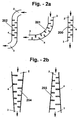
- the SASO-device conduit may be stretched in a straight line ( Figure-2a, 200), or aligned along a tortuous course ( Figure-2a, 201,202).
- Figure-2a illustrate only 2-dimensional aspect are shown SASO-device conduits course can also be tortuous in a three-dimensional manner, thus the fluid may be conveyed to any desirable direction, distance and location. Additionally, the downstream distribution of the conduit's cross-section area may be uniform (Figure-2a, 200), divergent (Figure-2b, 203), convergent ( Figure-2b, 204), or of any other practical distribution.
- the conduit cross-section might be of rectangular ( Figure-6a, 220,222), substantially circular (Figure-6a, 221,224), Polygon ( Figure-6a, 223), or of any other shape dictated by the specific engineering needs.
- the lateral dimension of the SASO-device conduit is denoted by " a " (see Figure-1b).
- the internal walls surface of the SASO-device conduit may be smooth or rough to enhance small scale turbulence within the thin boundary layers, attached to the conduit walls. In the case of rough walls, the skin friction is augmented.
- the conduit internal wall may also be provided with small extruding obstacles, preferably not greater than the boundary layer width, to enhance local flow separation that triggers wall turbulence.
- Fin (13), Figure-1b is a member of one of the two opposite fin arrays (14,15), forming the special internal geometry of the SASO-device.
- the objective of the fins is to force flow separation, and consequently to generate the vortical flow patterns.
- the fins may be positioned perpendicularly to the conduit walls, thus facing the flow, as illustrated in Figure-1b, Alternatively, the fins may be inclined with respect to both the general core-flow direction and the conduit walls.
- the surfaces of the fin may be flat or of any other predetermined surface geometry, to manipulate the separation characteristics.
- a typical fin span of a fin from one fin array is denoted by the dimension " b ", as shown in Figure-1b.
- the fin span of a fin of the opposite fin array, closest to the first fin of the first fin array, is denoted by " c ".
- the fin span of both fin arrays can be uniform as illustrated in Figure-1b, or varying.
- the fin tip (16) may be sharp or blunt, or of any reasonable shape.
- each of the fins substantially blocks half of the conduit, thus “ b “ and “ c “ are each substantially half of the hydraulic diameter " a ".
- the absolute value of " d " should be of a smaller order than the lateral dimension of the conduit " a ".
- said absolute value of said gap is not more than 20% of the adjacent lateral width of said conduit.
- the core-flow laterally sinusoidal motion does not exclusively depend on the gap " d " but also on the geometrical details of the fins.
- the laterally sinusoidal motion may be amplified when the through flow Reynolds Number is increased.
- local impingement of the core-flow at the edge area of the fins facing surface may be developed as shown in Figure-5c.
- the fin shape, and in particular the shape of the fin tip, may significantly affect the SASO-device performance, since the flow separates from the fin tip.
- the fin tip can be sharp (Figure-6c,230), round (Figure-6c,231) or of blunt cut ( Figure-6a, 232,233).
- the fin tip is usually a curve in real three dimensional cases, and the "separation point" is in fact a "separation curve", which is substantially normal to the core-flow motion direction.
- the "separation curve” may be a straight line, or of any predetermined curvature, in correspondence to the fin tip curvature or the lateral distribution of the fin span.
- the fin span can be laterally uniform (Figure-7c, 241), roundly curved ( Figure-7c, 242), symmetrically "V” shaped ( Figure-7c, 243), or laterally inclined (Figure-7c, 244),
- the "separation curve" may be fixed (stationary) to a substantially sharp or blunt fin tip, or of a non-stationary behavior.
- the non-stationary behavior can be dictated by the use of a round fin-tip.
- the fin surface may be smooth or rough, to generate small scale boundary layer turbulence.
- Unsteady character of the flow separation may significantly improve the SASO-device performance, as it may trigger complex unsteady vortical flow patterns that may block the through flow more efficiently.
- a SASO-device includes a plurality of fins.
- various fin combinations may be configured inside the conduit, to provide a SASO-device with improved characteristics. Without derogating generality the following combinations are available :
- SASO-cell is a cavity that is bounded by two consecutive fins (18,19), the conduit wall (20), and the conduit's center-line (21).
- the SASO-device comprises two substantially opposite arrays of consecutive SASO-cells, where in opposite each SASO-cell of the first set there exists one fin of the opposite set, as shown in Figure-1 b.
- the basic lateral scale of SASO-cell is substantially the fin height, " b " (or " c "), or approximately half of the conduit lateral dimension, " a / 2 ".
- the longitudinal gap between the fins, denoted by " e " in Figure-1b, is the SASO-cell pitch. Although it usually is the case, it is not always necessary to place the opposite fin facing the exact center of SASO-cells of the opposite set, and it may be off the center.
- the SASO-cell pitch " e " can be constant, or of any practical downstream distribution.
- the primary vortices are developed.
- the developed vortices are dynamic fluid structures that develop and survive within the SASO-cell, only when through flow is maintained inside the conduit.
- a vortex is a rotational motion of fluid around a fixed or an unsteady virtual axis.
- a steady vortex is a fully developed vortex, that induces a steady velocity field.
- the primary vortex is characterized by closed stream-lines as illustrated in Figures 1a and 1b . It means that there is no mass flow normal to the vortex stream-lines, thus it may serve as an efficient fluid barrier, just like the solid fins that face the incoming flow.
- the primary vortex When the primary vortex is of unsteady nature, but still maintained substantially within the SASO-cell, it may be distorted while moving periodically, or even chaotically. In such unsteady cases, the vortex streamlines are not necessarily closed and there is some mass exchange with the core-flow. Nevertheless, practically speaking, the vortex still serves as an effective "fluid" barrier.
- the unsteady nature of the primary vortices is of great importance in accordance to the present invention, because it can trigger complex interactions between the vortices and the core-flow. It can also trigger longitudinal interactions between the vortices. These interactions can be intentionally invoked and may significantly improve the efficiency of the aerodynamic blockage mechanism.
- FIGS 3a-3h illustrate some possible interactions between various vortical flow patterns with the SASO-cell walls, where interactions with the core-flow may be involved.
- An interaction of a steady character is shown in Figure-3a, where the principle substantially stationary vortex (6), is developed inside the SASO-cell.
- Figure-3b illustrates the case where weak non-steady interaction, mostly of a time-periodic nature, takes place where the vortex deforms and shifts inside the SASO-cell, and interacts with the core-flow.
- the vortex As the vortex swings about (in the directions represented by arrows (30)), it causes the core-flow to adjust, by locally altering its course to follow the "free passage", which shifts accordingly in the direction of arrows (31).
- the aerodynamic blockage effect may significantly be augmented when unsteadiness is introduced to the flow, for example by selecting the desired scales of the SASO-device.
- the two fundamental features of the present invention the significant increase of ⁇ P and the drastic reduction of MFR, are both modified.
- the various aspects of the aerodynamic blockage effects must be treated in terms of time-averaged quantities.
- Such small scale vortices can be intentionally initiated with the aid of a special cell geometry, see Figure-3d, where the conduit wall (12), is provided with a extruding construction element (34).
- a secondary vortex (35) of scales similar to these of the principal vortex, may develop (see Figure-3e).
- This secondary vortex (35) is usually of a reduced circulation.
- the principle vortex (6) may be forced by the core-flow (8), to a declined orientation inside the SASO-cell cavity.
- a small secondary vortex (35), or several vortices may develop in the "unoccupied" corner region of the SASO-cell, as shown in Figure-3f.
- a “free” (geometrically unforced) developed vortex has its own “natural” scales (by this term we mean integral scales as referred to in the art), that depends on the flow characteristics and its own formation history.
- the questions of matching between the vortex integrally defined natural scales associated with its vorticity, and the actual space available inside the SASO-cell, expressed by the term "spacing", is of great importance in the present invention.
- the vortex spatial growth is bounded by the SASO-cell walls in a two-dimensional manner.
- the vortex In certain situations, where the SASO-cell dimensions are effectively larger or smaller than the vortex integrally defined natural scales associated with its vorticity, the vortex, practically speaking, does not achieve its full potential, thus it is less effective with respect to the aerodynamic blockage mechanism. States of "optimal spacing" might be achieved, practically speaking, when the size of the SASO-cell is slightly smaller than the vortex integrally defined natural scales associated with its vorticity. In such a case the vortex practically achieves its full potential while it is slightly deformed and intensively interacts both with the SASO-cell walls and with the core-flow. The spacing issue is a most important aspect that affects the SASO-device performance.
- the SASO-device vortical flow pattern becomes more complex and involves unsteady flow mechanisms, as the Reynolds number (Re) increases.
- Re number When Re number is increased, unsteady secondary vortices may be developed between the core-flow and the principal vortex.
- the typical scales of these vortices are similar to the core-flow width, and is significantly smaller than the principle vortex. These are shed vortices that may develop and travel downstream in a periodic mode, with complex periodicity or even in a chaotic way. These shed vortices violently interact with the core-flow, and a core-flow of unsteady character is attained. When the shed vortices directly confront the core-flow, unsteady core-flow "break-down", may take place.
- Shed vortices (36) may exist locally inside the SASO-cell, as illustrated in Figure-3g. They can also travel downstream and interact with the consecutive SASO-cells, see Figure-3h.
- the unsteady nature of the flow may significantly modify the aerodynamic blockage effect, and affect the fundamental features of the present invention, i.e. increasing the ⁇ P and reducing the MFR. It is within the scope of SASO-technology to implement and harness the benefits of the unsteady vortical flow patterns.
- the appearance of traveling vortices which strongly interact with the core-flow and with the principle vortices may create downstream propagating wavy modes, where a plurality of vortices "communicate" with each other.
- instantaneous large changes in the lateral and in the longitudinal core-flow velocity may be locally developed. Consequently, the strongly disturbed core-flow may impinges in an unsteady fashion, on the facing fin.
- Reynolds number (Re) is further increased, (for example, by increasing the SASO-conduit lateral scale), more secondary vortices may be generated, and the direct interaction between the vortices and the core-flow becomes more violent.
- SASO-technology provides the necessary know-how required to utilize these unsteady vortices/core-flow interactions for the design of injection systems, of improved characteristics, used to generate aerodynamically induced forces.
- the present invention covers all these unsteady secondary vortices patterns. Therefore, the SASO-idea is hereafter extended to include also secondary shed vortices that may instantaneously block the core-flow.
- the core-flow lateral scale (or the core-flow width), is significantly narrower than the SASO-conduit hydraulic diameter.
- the core-flow velocity distribution and its width are essentially determined by the external pressure drop, the various SASO-device internal configurations, and particularly, by the vortical flow-field patterns that are developed inside the SASO-conduit.
- the initial core-flow is wider, characterized by a sinusoidal downstream fluid motion of large lateral amplitude, bounded by the fins and the conduit walls.
- the flow is very similar to the flow in conventional labyrinth type devices.
- a totally different flow-field develops inside the SASO-device conduit.
- the flow can not follow the internal passage defined by the walls of the special SASO-device configuration. Consequently, the flow separates at the fin tips, and two opposing arrays of intensive principle vortices are developed inside the SASO-cells. These arrays of vortices limit the passage of the flow through the conduit, and a detached, severely narrower, core-flow is obtained. In many cases, the core-flow involves unsteady vortical flow patterns, with respect to the predetermined Re number (when Re number is increased).
- the typical width of the core-flow is the effective hydraulic diameter of the SASO-cell conduit.
- a SASO-device that has a large lateral physical size (“ a ")
- a large lateral physical size (“ a ")
- the physical size and the effective size, regarding MFR through the SASO-conduit differ by orders of magnitude.
- This dual-scale behavior small effective scale in respect to the MFR and large physical dimensions
- the large physical scale is important with respect to significantly reducing the risk of contamination blockage in the case of fluids containing contaminants.
- the physical passage inside the SASO-conduit i.e.
- the winding passage within the conduit, between the fins) be greater than the envisaged size of the contaminant particles inside the fluid by at least 10%.
- the contaminants size can be predicted when the SASO-device is designated for a specific injection system used to generate aerodynamically induced forces, and therefore SASO-device scales relevant to that physical passage can be specified.
- SASO Self-Adaptive Segmented Orifice
- SAGU Self-Adaptive Gate Unit
- a SAGU is a "virtual" orifice unit consisting of two complementary elements, a solid element - the fin, and a dynamic element - a vortical fluid structure positioned between two fins of the opposite fin array (15).
- SAGU is a dynamic entity that exists as long as fluid motion through the conduit is maintained.
- SASO-device incorporating several SAGUs may be of appealing engineering advantage in two aspects:
- the second fundamental substance of the SASO in accordance with the present invention is the Segmentation Concept. In practice, it is beneficial to employ a combination of SAGUs, to configure a well functioning SASO-device. This is the essence of SASO-technology that provides SASO-devices with new or improved predetermined feature, to fulfill specific engineering requirements for Injection systems used to generate aerodynamically induced forces.
- a fundamental aspect of the present invention is the self-adaptive nature of SASO-devices. Such devices respond differently from conventional devices to changing or unsteady external conditions.
- SASO-devices are superior when external conditions are not stable or intentionally altered, or when adjustable functionality is required to meet different engineering requirements.
- the dynamic nature of the vortical flow pattern and the possible interactions of the vortices with the core-flow render the SASO its self-adaptive behavior.
- SASO-technology can be used to manipulate two essentially different engineering aspects:
- the SASO in accordance with a preferred embodiment of the aerodynamic blockage mechanism imposed by the Self-Adaptive Segmented Orifice of the present invention is effective as long as the SASO-device special configuration imposes the development of the vortical flow field patterns, thus achieving substantial control over the flow through the conduit.
- the transitional period also exhibits the multiple-functioning nature of the SASO, a most important feature of the present invention, where different performances are exhibited by the SASO-device at different working conditions, or when it operates at varying working conditions.
- the characteristics of the vortices and consequently MFR and ⁇ P strongly depend on various flow-field phenomena and, most importantly, on the internal configuration of the SASO-device conduit that dictates the internal vortical flow patterns.
- SAGU Self-Adaptive Gate Unit
- a SAGU includes the following elements :
- a SASO-device may consist of one or more SAGUs, sequentially arranged in an antisymmetric configuration as shown in Figure-1b.
- SAGUs When a plurality of SAGUs are used, unsteady vortical flow patterns, strong vortices/core-flow interactions and communication between SAGUs may significantly modify the practical characteristics of the SASO-device.
- the definition of the physical dimensions of the Tangential SAGU are similar to the dimensions defined for the Radial SAGU, except for the gap " d " that becomes irrelevant.
- Two variables, the angle " ⁇ ", and the distance " f ", define the effective gap of the Tangential SAGU as shown in Figure-4b.
- Angle " ⁇ " defines the orientation of the fins with respect to the conduit wall, and does not have to be identical for all the fins.
- the dimension " f " is the shortest distance between the tip of a fin from one set to the opposing fin of the second set, as shown in Figure-4b.
- Tangential SAGU Another distinct aspect of the Tangential SAGU in comparison with the Radial SAGU, is the change in fluid-dynamic resistance, when the fluid flow direction is reversed. It is due to the fact that while the Radial SAGU is of a "symmetric" nature with respect to flow direction, the Tangential SAGU has an "asymmetric” nature, in that respect.
- This tangential SAGU "dual behavior" may be beneficial, for instance, when a different fluid-dynamic resistance is required to inject or suck a fluid, in different operational stages, with different ⁇ P (or MFR) requirements.
- the second principle concept of the SASO of the present invention, and the SASO-technology is the Segmentation Concept. It states that specific engineering requirements can be fulfilled by a sequential arrangement of a plurality of SAGUs.
- a SASO-device can be configured with a plurality of identical type SAGUs, or by using a combination of more than one SAGU type.
- each SASO-device is characterized by a specific SAGU arrangement, the number of SAGUs, and the types of SAGUs used.
- SAGUs basic components
- the Segmentation Concept included in the SASO-technology procedure of design, involves the selection the SAGU types and the optimal number of SAGUs to be used, and the SAGU axial arrangements along the specific SASO-device.
- any combination of SAGUs in corporation with any configuration of the SASO-device inlet or outlet sections that are assembled together in the design, are all covered by the present invention. It is further noted that any variant of a SASO-device that is based substantially on the SASO-idea of vortical aerodynamic blockage including possible incorporation with various passive or active means, of various engineering disciplines, is covered by the scope of the present invention.
- the present invention involves a wide variety of SASO-devices with distinct configurations.
- Some optional SASO-devices that can be applied in injection systems used to generate aerodynamically induced forces are hereafter described, without limiting the scope of the invention as defined by the appended Claims.
- the basic SASO-device is the "SASO-tube" of rectangular cross section, illustrated in Figure-7a. It is essentially a three-dimensional SASO-device, where the third dimension of typical width "I2" is the "passive direction".
- the main fluid dynamic patterns are of a two-dimensional character, secondary flow effects of three-dimensional character may develop.
- the flow is of a three-dimensional nature when approaching the side walls (of the "passive” direction).
- “I2" ( Figure-7a) reaches a sufficiently small value, the flow becomes of significantly three- dimensional nature and viscous effects may significantly affect the SASO-tube performance. In particular it may cause an intensive decay of the vortical flow patterns, thus the aerodynamic blockage mechanism may be severely deteriorated.
- FIG.-7b Two side views and one top view of the basic two-dimensional configuration, are illustrated in Figure-7b.
- Lateral side view I shows the "active" dimension, with the two opposite fin arrays.
- Side view II shows a sectional view of both fin arrays appearing interlaced (this is of course not true, but the angle of view provides the interlacing effect).
- Top view III shows the first two opposite facing fins (4,5) at the inlet.
- fins of different laterally span distribution are optional, as shown in Figure-7c.
- FIG-6b illustrates several optional fin cross section or fin profiles
- the fin profile can be rectangular (212), sharp (211), curved (210) or of different fin's side surfaces (215).
- the arrays of fins can overlap (213) or not (212) or with no gap between them (211).
- the fins can be mounted perpendicularly to the SASO-conduit walls (212), or inclined with respect to the SASO-device conduit wall (214).
- the fin arrangement can provide a different behavior with respect to the direction of flow (214-215) or to be not sensitive to the flow direction (210-213).
- This basic SASO-device consists of a predetermined number of identical SAGUs, as stipulated by SASO-technology procedure of design, depending on the engineering requirements of a specific injection system used to generate aerodynamically induced forces.
- a modified SASO-device namely a "SASO-slot" is defined in cases where "I2" is the lateral length of the fin along the passive direction is considerably larger then “I1", the second lateral direction, as illustrates in Figure-6a (222).
- the flow is essentially two-dimensional, as the lateral scale of the boundary layers and the resulting viscous effects, at the edges of the slot, is practically negligible in respect to "I2". Consequently, the one-dimensional lateral suppression (by the vortices) of the core-flow width, or, alternatively speaking, the aerodynamic blockage mechanism, may be more efficient.
- Figure-7e shows a different "directional" SASO-device, where one surface of the fins (14,15) is, for example, flat and the opposite side of the fin is curved.
- the characteristics of the vortical flow patterns and the core-flow are manipulated differently, and the aerodynamic resistance varies, when the flow changes its direction.
- a SASO-device based on Tangential SAGU is a typical example of a Directional SASO-device.
- Figure-7f show different "directional" SASO-device, where the pitch or the distance between two consecutive fin changes substantially in a predetermined flow direction x
- FIG-8 illustrates an annular SASO-slot (50), having two opposite ring-shaped fins arrays (the top two fins are shown in Figure-8a, and see also fins (53, 54) in Figure-8b), where the annular SASO-slot conduit has an internal wall (52) of radius r 1 , and an external wall (51) of radius r 2 , as shown in Figure-8b.
- Figure-8b illustrates a sectional view of the annular SASO-slot, where two arrays of ring-shaped fins (53,54) are positioned within the internal walls (51, 52) of the annular conduit.
- the vortical pattern formed in an annular SASO-slot is in the form of two arrays of vortex-rings (55, 56). Note that in this configuration the core-flow suppression by the vortex-rings is also of a one-dimensional character.
- FIG. 9a A different type of a SASO-device, of a three dimensional character, is presented in Figure-9a.
- This type of a SASO-device has a conduit of lateral rectangular cross section (Figure-9b) with "L" shaped fins (14,15), that are consecutively located at opposing corners.
- Figure-9c depicts a longitudinal cross section view (cross-section A-B as shown in Fig. 9b ), of the first fins (segment U and segment D) arrangement inside the SASO-device.
- the core-flow is laterally suppressed by the vortices in a two-dimensional manner.
- Two-dimensional suppression is the most significant issue of three- dimensional variants of SASO-device, where in a two-dimensional SASO-device variants, the core-flow lateral suppression is of one-dimensional character.
- the aerodynamic blockage efficiency of three-dimensional SASO-device configurations is expected to be significantly improved, expected to improve.
- Figure-9d Another similar alternative is shown in Figure-9d, where "U" shaped fins (14,15) are mounted within a conduit having a polygon cross-section.
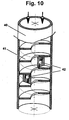
- Figure-10 illustrates a longitudinal cross-section view of a SASO-device comprising a conduit (40), here possessing circular lateral cross section, with a single fin (41) presenting an internal helical structure. It is in fact one helical fin, optionally provided with barriers (42) distributed along the device to enforce flow separation and prevent a natural selection of a helical flow motion that may be triggered at specific combinations of the geometrical parameters. Note that the presence of such barriers is not essential, but may improve flow separation.
- both fin ends may be provided with extruding rims, projecting substantially normal to the fin surface, used as a seat to hold the helical vortex at its both ends.
- this type of a SASO-tube offers an alternative passage - the helical route - to overcome this obstacle locally, and then resume the central separation route, in a self adaptive manner or it is forced to resume the central separation route by the next barrier (if it exists).
- This dual passage character is of great practical importance since it offers a SASO-device with its advantages, that is "almost free” of mechanical blockage, and can thus operate well in specific injection system used for aerodynamically induced forces applications, where severe contamination environment exists.
- SASO-devices (such as the fin construction, size, texture and shape, etc.) apply accordingly to the helical fin SASO-device too.
- a common injection system of the present invention used to generate aerodynamically induced forces is the air-cushion apparatus.
- a supporting or conveying system uses air injection to generate air-cushions to support the objects to be conveyed with no contact with a solid surface, thus it either protects the object from a contact damage, or conveys it applying significantly less energy, as the friction coefficient is greatly reduced, or both.
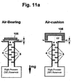
- FIG 11 illustrates an injection system used to generate an aerodynamically induced force, with accordance to the present invention, serving as an air-cushion non-contact supporting system.
- the system comprises a high pressure manifold (101), connected by high pressure pipe (103), to a high pressure source (102).
- a SASO-conduit (1) whose inlet (2) is connected to the high pressure manifold, and the outlet (3) is located on the injection-surface (104), of the injection system.
- the internal configuration of the SASO-conduit can be selected from the embodiments shown in Figures 1-10 , or can be of any other SASO-conduit configuration covered by the scope of the appending Claims. The selection of specific design is done with regards to the specific engineering requirements.
- Figure-11 shows three positions of an object (105), being supported by an air-cushion produced by the injection system in an non-contact manner.
- position “b” the object is at a distance X from the SASO-conduit outlet, and there is an equilibrium between the object weight -mg, and the aerodynamically induced force F.
- position “a” the distance X to the SASO-conduit outlet is decreased and the force F increases and pushes the object back to equilibrium position "b”.
- This position control of self-adaptive nature results from the SASO "fluidic return spring” behavior.
- position “c” the distance X increases with the force F decreasing, thus the object weight pulls the object back to its equilibrium position "b”. This equilibrium position is unconditionally stable.
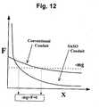
- Figure-12 illustrates the relation between the distance X and the aerodynamically induced forces F, that act on an object being supported by an air-cushion injection system based on SASO-conduits, with comparison to a similar air-cushion system equipped with conventional conduits.
- the advantage of employing SASO-conduits for air-cushion support is illustrated in Figure-12, where the SASO fundamental feature of sustaining large internal pressure drop is beneficially implemented.
- the object When air is injected through one or more SASO-conduits, the object is at equilibrium position in a much shorter distance X with respect to conventional conduits. As X decreases, with the SASO-conduit outlet being almost covered, most of the manifold high pressure applied at the SASO-conduit inlet is introduced to the outlet due to a decay of the vortical aerodynamic blockage effect within the SASO-conduit, and the internal pressure drop ⁇ P, is dramatically reduced. Therefore, when the object is not in equilibrium and the distance X decreases, the SASO-conduit "aerodynamic return spring" possess a "stiff' character, where the stiffness directly relates, to the internal pressure drop ⁇ P through the SASO-conduit.
- the SASO-conduit exhibits an "aerodynamic return spring” that acts as a self-adaptive positioning control mechanism, where much larger aerodynamic return force (relative to conventional conduits) pushes the object back to the equilibrium position, mainly by increasing the static pressure between the injection system "injection-surface” and the object. It means that due to the potential of the SASO-conduit to sustain large internal pressure drop ⁇ P, the control characteristics with respect to the object positioning is improved. Furthermore, when SASO-conduits are used, the equilibrium position X become significantly smaller, thus accurate positioning control can be obtained, compared to conventional conduits.
- the characteristics or the sensitivity of the SASO-conduit self-adaptive positioning control is, in fact, the slope of the curve F.vs.X that is given in Figure-12, where, with respect to conventional conduits, the SASO-conduit slope is extremely steeper at equilibrium position and thus the control characteristics is significantly improved.
- the distance X is the distance between the outlet and the lower surface of the object over it, for flat objects.
- An air bearing system shown in Fig. 11a is a typical example, where object (105) presents a flat lower surface to the SASO-device outlet.
- the effective distance from the outlet is the distance of the rim which governs the pressure build-up inside the cavity. This feature can be utilized in an air-cushion application.
- FIG. 13a A typical embodiment of an air-cushion conveying system in accordance with the present invention is shown schematically in Figures-13a.
- a high-pressure sources (20) connected through a pressure hose (20a) to a manifold (21).
- the air is injected through a plurality of SASO-conduits (22) and exits through the conduit outlets (24) at the "injection-surface" of the injection system (23).
- the injected air generates air bed (26) that supports the "floating" object (25), equipped with the injection system.
- the air bed is generated between the object surface and the conveying-route floor (27).
- the object floats in a steady state equilibrium, where the object weight is balanced by the air-cushion aerodynamically induced force.
- the aerodynamically induced force resulted from the SASO based injection system with accordance to the present invention has superior performance in comparison with conventional conduits in two aspects: A much higher positioning accuracy and improved positioning control characteristics of self adaptive nature, can be obtained due to the enhanced "aerodynamic return spring" performance of injection system that uses the SASO. In addition, the MFR requirements are significantly reduced.
- FIG-13b Another embodiment of an air-cushion conveying system is illustrated in Figure-13b.
- High pressure source (30) connected through a pressure hose (30a) to an elongated manifold (31).
- the air is injected through a plurality of SASO-conduits (32) exiting through the conduits outlets (34) at the injection-surface of an inert injection system (33).
- the injected air generates an air bed (36) that supports the object (35) that is floating with no contact.
- an air-cushion is generated, but in this example the injection system is the fixed-in-place conveyer route itself.
- the superiority of employing SASO-technology is already discussed in the previous example.
- the inert injection system suffers from a gradually increased parasitic MFR from a plurality of conduits that are not contributing to generate the aerodynamically induced force but they unnecessarily expend (parasite) mass flow.
- a gradually increased parasitic MFR from a plurality of conduits that are not contributing to generate the aerodynamically induced force but they unnecessarily expend (parasite) mass flow.
- Air-bed supporting or non-contact conveying apparatus may apply fluid injection from more than one direction in various applications. In some case it is important to maintain a distance between a moving objects and stationary surfaces, and in the same time guide the objects in specific routes. This can be achieved by injection from several directions to apply the aerodynamically induced forces to maintain the desired temporal positioning of the conveyed objects.
- Figure-14a is a schematic representation of such a system, where gravity is irrelevant (thus horizontal or vertical or any other alignment combination is allowed).
- a flat object (43) possibly flexible (such as paper), is supported or conveyed, between two opposite injection-surfaces, in a pathway defined between the surfaces.
- a high pressure reservoir (40) feeds the two pressure manifolds (41), pressurized air is injected through SASO-conduits (42), provided to both of the injection system injection-surfaces.
- the air injection generates two air-cushions that support the object (43) from its two sides.
- the aerodynamic induced forces are in equilibrium when the object surface is in a same distance from both injection surfaces, as required. When the object shifts closer to one of the surfaces, the aerodynamically induced forces which vary with that distance, change as well. The change of the aerodynamically induced is opposite to the change in the distance, thus the positioning control, of self-adaptive nature, acts as two opposing aerodynamic return springs to return the object back to the required position.
- the injection system of the present invention can be also used to generate a linear motion by using the perpendicular (with respect to the manifold surface) component of the aerodynamically induced force, as seen in Figure-14b.
- a high pressure source (50) feeds two manifolds (51).
- the pressurized air is injected through SASO-conduits (52) located in both injection system injection-surfaces, in an inclined orientation with respect to the injection system injection-surfaces.
- the air injection generates two air-cushion that support the flat object (53) from two sides.
- the object in addition, is aerodynamically forced to move in a predetermined direction, determined by the direction of inclination of the SASO-conduits (52), the movement evoked by viscous friction forces generated by the parallel flow.
- the previously discussed advantages of using SASO-conduits in the present invention are also relevant for such air-cushion types of injection systems, and in particular, the aspects of position control and MFR reduction.
- Air-bed of supporting or conveying systems need not be restricted to flat surfaces only, and cylindrical geometry is also allowed, as demonstrated in Figure-15.
- internal high pressure reservoirs (60), or external reservoir (61) are used.
- the system comprises a cylindrical air support surface (64) provided with a plurality of SASO-conduits (62), whose outlets lay on the injection-surface of the cylinder, and whose inlets are connected to the internal high pressure reservoir (60).
- SASO-conduits whose outlets lay on the injection-surface of the cylinder, and whose inlets are connected to the internal high pressure reservoir (60).
- an additional matching support surface (65) is provided below support surface (64), again having a high pressure reservoir (61) connected to a plurality of SASO-conduits (62), whose outlets lay on the cylindrical injection-surfaces.
- the conveyed object - sheet (63) - is suspended within the passage provided between the surfaces, held at equilibrium by the opposite forces exerted on it by the air-cushions from both sides and beneficially implements the "aerodynamic return spring" advantages of the SASO-conduit.
- the air is injected through SASO-conduit (62) located on the outer surfaces of two cylinders (63,64), and the inner surface of one semi-cylinder (65). Air beds are generated between the cylindrical surfaces and the moving flexible sheet (66), that could be paper or plastic sheet or any other sheet that needs to be supported without contact.
- the supporting cylinder (63) generates aerodynamically induced forces of self-adaptive nature with respect to positioning control, and the aerodynamically induced force is balanced by the sheet tension.
- the inner cylinder (64) and the outer semi-cylinder (65) that support the sheet in both sizes exhibit similar positioning control character, but in contrast, the balanced position is not significantly affected by the sheet tension, where the balance is achieved by two sided air-cushions.
- FIG. 16a Another injection system using SASO-conduit to generate aerodynamically induced forces is a multi-directional positioning control system.
- Such application is, for example, the monorail air-cushion supporting system, shown in Figures-16a.
- the monorail base (70) supports a carriage (71) that equipped with a high pressure air source (72) and manifolds (73,74).
- High pressurized air is injected through sets of SASO-conduits (75,76) and air-cushions are generated to support the object that is moving along the monorail and control its position in a two-directional manner.
- two injection systems are involved in such a non-contact injection system. The first one is responsible for the vertical positioning.
- the second injection system is responsible for the horizontal or lateral positioning control, where the air is injected from a designated high pressure manifolds (74), through SASO sets of conduits (76), and generate two opposing air-cushions.
- These air-cushions serve as aerodynamic positioning control mechanism of self-adaptive manner from both horizontal sides, a similar positioning control situation to the apparatus presented in Figure-14a. Accordingly, the advantages of implementing SASO-technology for non-contact positioning control, are previously discussed.
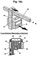
- FIG-16b Similar air-cushion injection system is shown in Figure-16b.
- a hooked carriage (81) supports by a hook (87) to the monorail (80).
- This injection system includes a high pressure air source (82) and manifolds (83,84).
- the high pressure air is injected through sets of SASO-conduits (85,86), in order to generate the air-cushions to support the object that is moving along the monorail and to control its position in a two-directional manner with no contact. All the details given for the previous air-cushion injection system shown in Figure-16a, are also relevant for this SASO-technology application.
- a different application based on high pressure injection can be applied in spindles that use air bearings.
- a schematic description of such an application can be found in Figure-17.
- a rotor component of the spindle (91), rotates in high angular speed, is supported by a thin air-cushion (92), produced by an air injection system in accordance with a preferred embodiment of the present invention.
- the pressurized air at the high pressure reservoir (93), located within the stator component (90) of the spindle, is injected through a plurality of SASO-conduits (94) connected by their inlets to the high pressure reservoir (93) attached to the stator component.
- the injected air is issued from the inner cylindrical surfaces of the spindle stator.
- the spindle rotor usually supports a tool (95) at its end, and as a result, it is subjected to side forces, whose direction is indicated by arrow 96, applied on the tool while rotating. It is important to maintain the radial positioning of the rotor at a very high accuracy of order of ⁇ -meter (for example: dicing applications in the semi-conductor industry).
- Currently known spindles apply a plurality of small diameter conventional injection conduits, that consume high MFR, to achieve an effective "aerodynamic return spring" for controlling the radial positioning in a self-adaptive manner, especially when it is subjected to the side force.
- the SASO aerodynamic return spring effect is superior in comparison with conventional conduits.
- FIG. 18 A different group of applications that implements the novel SASO injection system to generate aerodynamically induced forces, with accordance to the present invention, is the Upper Non-Contact Gripping (or the UNCG) device, as schematically demonstrated in Figure-18.
- This application uses two contradictory aerodynamically induced forces : (a) vacuum suction that pulls the object toward the UNCG injection-surface and (b) injection of pressurized air through SASO-conduits that pushes the object away from that injection-surface.
- Figure 18 shows an UNCG apparatus, that may serve as a robot arm, in three distinct positions (a,b,c) in respect to the distance from the UNCG injection-surface to the object to be supported.
- the UNCG has two interlaced manifolds, a vacuum manifold (100) generates a vacuum suction that is applied through one or more conventional vacuum pads (103) to generate the lifting aerodynamically induced force.
- the opposing aerodynamically induced force acting in the direction of the gravity, is supplied from a high pressure air manifold (101) that injects air that impinges on the object through one or more SASO-conduits (102).
- the two contradictory aerodynamically induced forces act simultaneously on the object to be supported with no-contact, and the twin components of the total aerodynamically induced force and the gravity are in equilibrium.
- Another alternative to generate a fluidic suction effect can be obtained by using a system (104) that accelerates the air to low static pressure and introduces the accelerated air in parallel to the object surface to generate low pressure (LP) on portion of the object surface, where the rejecting high pressure (HP) aerodynamically induced forces is obtained by injection through SASO-conduits (105) onto other portion of the object's surface, as shown in Figure-18a. Consequently, a similar two contradictory aerodynamically induced forces can be obtained.
- Figure-19 illustrates the relation between the displacement - ⁇ X (the distance from the UNCG injection-surface to the object surface), and the aerodynamically induced forces in a SASO based UNCG system.
- the lifting aerodynamically induced force that basically balances the gravity is generated by vacuum suction. Relatively speaking (with respect to the injection force), the vacuum suction induced force is characterized by a long range effect as shown in Figure-19 (curve vf, represents the vacuum force).
- curve vf represents the vacuum force.
- the contradictory rejecting force, generated by high pressure injection through the SASO-conduit, is characterized by a relatively short range effect, (curve -pf represents the rejecting force, where the sign minus (-) indicates that the force acting in the gravitational force direction, i.e. downwards).
- the object can be held or conveyed by the combined force (Af), where the object is "floating" and does not come with physical contact with the UNCG injection-surface. It can be for example, a robot arm that holds an object with no contact from its upper side.
- Af combined force
- the UNCG system uses injection through one or more SASO-conduits to produce the short range rejecting force, it is covered by the scope of the present invention.
- SASO-conduits are used, the UNCG system is covered by the scope of the present invention also if any mechanism, fluidic or non fluidic, is implemented to produce the contradictory force that is employed to attract the object.
- applications of UNCG systems may involve gravity force but it also may not be related in any sense to gravity, and as long as SASO-conduits are used for injection, the UNCG system is covered by the scope of the present invention.
- FIG-20a a typical UNCG system in accordance with a preferred embodiment of the present invention, is shown in Figure-20a. It is a robot arm that may be applicable in the semiconductor industry to support wafers without having a physical contact with them.
- a central housing 109 provided with a SASO-conduit (119), connect to a high pressure reservoir (117), and two vacuum ports (116), positioned about said SASO-conduit, on either side of it.
- a large wafer (110) that is already supported with contact at its edges (111) is supported by the combined aerodynamically induced force to remain flat, preventing its deformation (112) due to its own weight, and maintaining a required positioning (113).
- the vacuum leg of the UNCG system includes a vacuum source (114), vacuum suction pipelines (115) and one or more conventional suction ports (116).
- the contradictory injection leg of the UNCG system includes high pressure source (117), high pressure pipelines (118) and one or more SASO injection ports (119).
- a peripheral UNCG support of such a wafer (120) is suggested in Figure-20b, where four peripheral arms (121) are used to hold the object in a non-contact fashion (122).
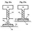
- the last example for injection system that produced aerodynamically induced forces is a system where one or more SASO-conduits are used to produce forces that holds down an object by high pressure injection on top of it as shown in Figures 21 a and 21b.
- the pressurized air from a high pressure source (130) is injected through SASO-conduits (131) towards the object (132) and forced it to attach to the underneath supporting surface (133).
Landscapes
- Engineering & Computer Science (AREA)
- Physics & Mathematics (AREA)
- Fluid Mechanics (AREA)
- Mechanical Engineering (AREA)
- General Engineering & Computer Science (AREA)
- Linear Motors (AREA)
- Jet Pumps And Other Pumps (AREA)
- Catching Or Destruction (AREA)
- Paper (AREA)
- Fluid-Damping Devices (AREA)
- Magnetic Bearings And Hydrostatic Bearings (AREA)
- Bearings For Parts Moving Linearly (AREA)
- Nozzles (AREA)
- Delivering By Means Of Belts And Rollers (AREA)
Applications Claiming Priority (3)
| Application Number | Priority Date | Filing Date | Title |
|---|---|---|---|
| IL131589A IL131589A (en) | 1999-08-25 | 1999-08-25 | Device for creating forces by injecting liquid |
| IL13158999 | 1999-08-25 | ||
| PCT/IL2000/000500 WO2001014752A1 (en) | 1999-08-25 | 2000-08-20 | Apparatus for inducing forces by fluid injection |
Publications (3)
| Publication Number | Publication Date |
|---|---|
| EP1222404A1 EP1222404A1 (en) | 2002-07-17 |
| EP1222404A4 EP1222404A4 (en) | 2008-06-25 |
| EP1222404B1 true EP1222404B1 (en) | 2011-10-05 |
Family
ID=11073182
Family Applications (1)
| Application Number | Title | Priority Date | Filing Date |
|---|---|---|---|
| EP00953419A Expired - Lifetime EP1222404B1 (en) | 1999-08-25 | 2000-08-20 | Apparatus for inducing forces by fluid injection |
Country Status (9)
| Country | Link |
|---|---|
| US (1) | US6523572B1 (https=) |
| EP (1) | EP1222404B1 (https=) |
| JP (1) | JP4658425B2 (https=) |
| KR (1) | KR100673114B1 (https=) |
| AT (1) | ATE527454T1 (https=) |
| AU (1) | AU6591800A (https=) |
| CA (1) | CA2382878C (https=) |
| IL (1) | IL131589A (https=) |
| WO (1) | WO2001014752A1 (https=) |
Families Citing this family (34)
| Publication number | Priority date | Publication date | Assignee | Title |
|---|---|---|---|---|
| US6637668B2 (en) * | 2001-10-24 | 2003-10-28 | Magarl, Llc | Thermostatic control valve with fluid mixing |
| TWI222423B (en) | 2001-12-27 | 2004-10-21 | Orbotech Ltd | System and methods for conveying and transporting levitated articles |
| DE10304618B4 (de) | 2002-03-25 | 2018-10-18 | Heidelberger Druckmaschinen Ag | Labyrinthdüse |
| US20050126605A1 (en) * | 2003-12-15 | 2005-06-16 | Coreflow Scientific Solutions Ltd. | Apparatus and method for cleaning surfaces |
| DE102004004396A1 (de) * | 2004-01-29 | 2005-08-11 | Heidelberger Druckmaschinen Ag | Vorrichtung zur Erzeugung gedrosselter Blas- oder Saugluft |
| KR20070006768A (ko) | 2004-03-17 | 2007-01-11 | 코레플로우 사이언티픽 솔루션스 리미티드 | 비접촉 열 플랫폼 |
| JP4767251B2 (ja) * | 2004-04-14 | 2011-09-07 | コアフロー サイエンティフィック ソリューションズ リミテッド | 光学検査装置を平坦な対象物の接面に対して焦点合わせする方法 |
| US20060108014A1 (en) * | 2004-11-23 | 2006-05-25 | Marsh Andrew D | Automotive power steering systems |
| JP4664117B2 (ja) * | 2005-03-03 | 2011-04-06 | 住友重機械工業株式会社 | 搬送物浮上ユニット、搬送物浮上装置、及びステージ装置 |
| JP4770312B2 (ja) * | 2005-07-26 | 2011-09-14 | トヨタ自動車株式会社 | ガスの希釈器 |
| KR20080059207A (ko) * | 2005-09-15 | 2008-06-26 | 코레플로우 사이언티픽 솔루션스 리미티드 | 컨베이어의 컨베잉 성능을 향상시키는 기구 및 방법 |
| JP4713397B2 (ja) * | 2006-01-18 | 2011-06-29 | 株式会社リコー | 微小流路構造体及び微小液滴生成システム |
| US7824470B2 (en) * | 2006-01-18 | 2010-11-02 | United Technologies Corporation | Method for enhancing mass transport in fuel deoxygenation systems |
| JP4841376B2 (ja) * | 2006-02-07 | 2011-12-21 | 大日本スクリーン製造株式会社 | 基板処理装置 |
| US20070289843A1 (en) * | 2006-04-18 | 2007-12-20 | Barry Kitazumi | Conveyor System Including Offset Section |
| WO2007132797A1 (ja) | 2006-05-16 | 2007-11-22 | National Institute Of Advanced Industrial Science And Technology | 板ガラスのロール成形製造方法及び装置並びにその製品 |
| US20080003325A1 (en) * | 2006-06-30 | 2008-01-03 | Seaver Richard T | Baffle for mold cooling systems |
| US20080050208A1 (en) * | 2006-08-25 | 2008-02-28 | Barry Kitazumi | High speed transporter including horizontal belt |
| IL183693A0 (en) * | 2007-06-05 | 2007-09-20 | Nova Measuring Instr Ltd | Optical method and system |
| EP2250109B1 (en) * | 2008-03-11 | 2015-01-14 | Coreflow Ltd. | Method and system for locally controlling support of a flat object |
| EP2294017A4 (en) * | 2008-06-18 | 2012-04-25 | Peta Entpr Ltd | IMPROVEMENTS IN WATER TREATMENT SYSTEMS |
| DE102008050153B4 (de) | 2008-10-01 | 2022-02-03 | Rational Ag | Gargerät mit Wärmetauscherleitung |
| JP2012099637A (ja) * | 2010-11-02 | 2012-05-24 | Kawamura Electric Inc | 冷却水配管機構を備えたサーバーラック |
| US8920071B2 (en) * | 2011-09-07 | 2014-12-30 | Hazard Mitigation, Inc. | Apparatus and method for limiting ice formation |
| DE102013010943B4 (de) * | 2012-07-26 | 2024-03-14 | Heidelberger Druckmaschinen Ag | Bogenleitvorrichtung |
| KR101415072B1 (ko) * | 2012-09-18 | 2014-07-04 | 삼성중공업 주식회사 | 유동 저항 저감장치 |
| JP6134191B2 (ja) | 2013-04-07 | 2017-05-24 | 村川 惠美 | 回転型セミバッチald装置 |
| US20160102797A1 (en) * | 2013-05-24 | 2016-04-14 | Nigel Richard Farrow | Improvement to material flow |
| US10381256B2 (en) | 2015-03-12 | 2019-08-13 | Kla-Tencor Corporation | Apparatus and method for chucking warped wafers |
| US9889995B1 (en) * | 2017-03-15 | 2018-02-13 | Core Flow Ltd. | Noncontact support platform with blockage detection |
| JP7098512B2 (ja) * | 2018-12-03 | 2022-07-11 | 三菱重工業株式会社 | 流路抵抗体、及び熱交換器 |
| EP3969400A4 (en) | 2019-05-16 | 2023-06-14 | Core Flow Ltd. | SUCTION CUP FOR DISTORTED WORKPIECE |
| CN113008731A (zh) * | 2021-02-25 | 2021-06-22 | 辽宁省计量科学研究院 | 整体浮动式带有温度修正功能的浮球称重法密度计 |
| US11578738B1 (en) * | 2022-06-22 | 2023-02-14 | Yongzhen Du | Vortex water flow accelerator |
Family Cites Families (17)
| Publication number | Priority date | Publication date | Assignee | Title |
|---|---|---|---|---|
| US1877567A (en) * | 1931-09-02 | 1932-09-13 | William P Erbes | Hot and cold water mixer for showers |
| US3785405A (en) * | 1972-02-23 | 1974-01-15 | Us Air Force | Aerodynamic nozzles in rectangular duct |
| US3870236A (en) | 1973-03-14 | 1975-03-11 | Sahagun Barragan Jaime | Dripping irrigation tubing |
| US3896999A (en) | 1973-09-28 | 1975-07-29 | Jaime Sahagun Barragan | Anti-clogging drip irrigation valve |
| IL45466A (en) | 1974-08-14 | 1976-07-30 | Hydro Plan Eng Ltd | Drip irrigation |
| US4573640A (en) | 1976-10-26 | 1986-03-04 | Hydro-Plan Engineering Ltd. | Irrigation emitter unit |
| IL50766A (en) | 1976-10-26 | 1983-06-15 | Hydro Plan Eng Ltd | Irrigation emitter unit |
| US4314587A (en) * | 1979-09-10 | 1982-02-09 | Combustion Engineering, Inc. | Rib design for boiler tubes |
| IL60071A (en) | 1980-05-14 | 1990-02-09 | Gilead Gideon | Apparatus for drip irrigation |
| US4334897A (en) * | 1981-02-24 | 1982-06-15 | Andersen 2000, Inc. | Gas scrubbing apparatus |
| JPS6010238B2 (ja) * | 1981-09-09 | 1985-03-15 | 千代田化工建設株式会社 | 配管系内気流体の脈動防止装置 |
| US4430020A (en) | 1982-09-29 | 1984-02-07 | Robbins Jackie W D | Drip irrigation hose |
| IL70646A (en) * | 1984-01-09 | 1990-07-26 | Naan Mech Works | Vortex labyrinth insert particularly for drip irrigation pipes |
| US4880167A (en) | 1987-09-23 | 1989-11-14 | James Hardie Irrigation, Inc. | Irrigation hose with linear turbulent flow emitter |
| US5620143A (en) | 1994-10-24 | 1997-04-15 | Drip Tape Manufacturers & Engineers, Inc. | Constant-flow irrigation tape and method of making |
| US5830515A (en) * | 1996-09-18 | 1998-11-03 | Pleasant Precision, Inc. | Mold insert |
| DE19806513A1 (de) * | 1998-02-17 | 1999-08-19 | Evert | Konstruktive Elemente zur Verbesserung des Fluidstroms in Rohren |
-
1999
- 1999-08-25 IL IL131589A patent/IL131589A/en not_active IP Right Cessation
-
2000
- 2000-08-20 KR KR1020027002370A patent/KR100673114B1/ko not_active Expired - Lifetime
- 2000-08-20 AU AU65918/00A patent/AU6591800A/en not_active Abandoned
- 2000-08-20 AT AT00953419T patent/ATE527454T1/de not_active IP Right Cessation
- 2000-08-20 WO PCT/IL2000/000500 patent/WO2001014752A1/en not_active Ceased
- 2000-08-20 JP JP2001518597A patent/JP4658425B2/ja not_active Expired - Lifetime
- 2000-08-20 CA CA002382878A patent/CA2382878C/en not_active Expired - Lifetime
- 2000-08-20 US US10/070,264 patent/US6523572B1/en not_active Expired - Lifetime
- 2000-08-20 EP EP00953419A patent/EP1222404B1/en not_active Expired - Lifetime
Also Published As
| Publication number | Publication date |
|---|---|
| US6523572B1 (en) | 2003-02-25 |
| WO2001014752A1 (en) | 2001-03-01 |
| EP1222404A4 (en) | 2008-06-25 |
| AU6591800A (en) | 2001-03-19 |
| ATE527454T1 (de) | 2011-10-15 |
| KR20020037347A (ko) | 2002-05-18 |
| WO2001014752A8 (en) | 2001-07-12 |
| CA2382878C (en) | 2006-11-14 |
| IL131589A0 (en) | 2001-01-28 |
| JP2003507681A (ja) | 2003-02-25 |
| IL131589A (en) | 2007-05-15 |
| CA2382878A1 (en) | 2001-03-01 |
| KR100673114B1 (ko) | 2007-01-22 |
| EP1222404A1 (en) | 2002-07-17 |
| JP4658425B2 (ja) | 2011-03-23 |
Similar Documents
| Publication | Publication Date | Title |
|---|---|---|
| EP1222404B1 (en) | Apparatus for inducing forces by fluid injection | |
| US6644703B1 (en) | Self-adaptive vacuum gripping system | |
| WO2001014782A1 (en) | Self adaptive segmented orifice device and method | |
| KR101296704B1 (ko) | 비접촉 반송 장치 | |
| US6701957B2 (en) | Fluid pressure reduction device | |
| EP2527675B1 (en) | Static pressure bearing device and stage provided with same | |
| US20030075615A1 (en) | Synthetic jet actuators | |
| US8950431B2 (en) | Fluid flow control device | |
| Ferreira Da Silva | On why and how do rivers meander | |
| JPS63501709A (ja) | ガスノズル組み立て体 | |
| Chang et al. | Dynamics of the forced wake of a square cylinder with embedded flapping jets | |
| EP0705212B1 (en) | Damperless controlled speed air conveyor and method of conveying articles en masse | |
| US4822181A (en) | Hydrostatic support device and method | |
| Hirata et al. | A novel pneumatic actuator system realised by microelectro-discharge machining | |
| EP0043457B1 (en) | Air film transportation device | |
| US6360763B1 (en) | Control of flow separation with harmonic forcing and induced separation | |
| CN102180442A (zh) | 一种微颗粒捕获装置及应用该装置的微颗粒输运设备 | |
| CN202131084U (zh) | 一种微颗粒捕获装置及应用该装置的微颗粒输运设备 | |
| JP2558508B2 (ja) | ストリップの流体支持装置 | |
| JP2005147318A (ja) | アクティブ振動制御装置及びシステム | |
| Tesař et al. | Lift and separation control on wind turbine blades by vortices having streamwise oriented axes | |
| Suzuki et al. | Synthesized mixing process in an actively-controlled confined coaxial jet | |
| TR2025018683A2 (tr) | Akişkan perdesi̇ tabanli taşima üreti̇m ci̇hazi | |
| CN114086501B (zh) | 一种可控佛汝德数的水槽供水控制及消能装置 | |
| JP3932347B2 (ja) | 縦渦発生装置 |
Legal Events
| Date | Code | Title | Description |
|---|---|---|---|
| PUAI | Public reference made under article 153(3) epc to a published international application that has entered the european phase |
Free format text: ORIGINAL CODE: 0009012 |
|
| 17P | Request for examination filed |
Effective date: 20020325 |
|
| AK | Designated contracting states |
Kind code of ref document: A1 Designated state(s): AT BE CH CY DE DK ES FI FR GB GR IE IT LI LU MC NL PT SE |
|
| AX | Request for extension of the european patent |
Free format text: AL;LT;LV;MK;RO;SI |
|
| A4 | Supplementary search report drawn up and despatched |
Effective date: 20080528 |
|
| 17Q | First examination report despatched |
Effective date: 20081027 |
|
| GRAP | Despatch of communication of intention to grant a patent |
Free format text: ORIGINAL CODE: EPIDOSNIGR1 |
|
| GRAS | Grant fee paid |
Free format text: ORIGINAL CODE: EPIDOSNIGR3 |
|
| GRAA | (expected) grant |
Free format text: ORIGINAL CODE: 0009210 |
|
| AK | Designated contracting states |
Kind code of ref document: B1 Designated state(s): AT BE CH CY DE DK ES FI FR GB GR IE IT LI LU MC NL PT SE |
|
| REG | Reference to a national code |
Ref country code: GB Ref legal event code: FG4D |
|
| REG | Reference to a national code |
Ref country code: CH Ref legal event code: EP |
|
| REG | Reference to a national code |
Ref country code: IE Ref legal event code: FG4D |
|
| REG | Reference to a national code |
Ref country code: DE Ref legal event code: R096 Ref document number: 60046518 Country of ref document: DE Effective date: 20111208 |
|
| REG | Reference to a national code |
Ref country code: NL Ref legal event code: VDEP Effective date: 20111005 |
|
| REG | Reference to a national code |
Ref country code: AT Ref legal event code: MK05 Ref document number: 527454 Country of ref document: AT Kind code of ref document: T Effective date: 20111005 |
|
| PG25 | Lapsed in a contracting state [announced via postgrant information from national office to epo] |
Ref country code: BE Free format text: LAPSE BECAUSE OF FAILURE TO SUBMIT A TRANSLATION OF THE DESCRIPTION OR TO PAY THE FEE WITHIN THE PRESCRIBED TIME-LIMIT Effective date: 20111005 |
|
| PG25 | Lapsed in a contracting state [announced via postgrant information from national office to epo] |
Ref country code: GR Free format text: LAPSE BECAUSE OF FAILURE TO SUBMIT A TRANSLATION OF THE DESCRIPTION OR TO PAY THE FEE WITHIN THE PRESCRIBED TIME-LIMIT Effective date: 20120106 Ref country code: NL Free format text: LAPSE BECAUSE OF FAILURE TO SUBMIT A TRANSLATION OF THE DESCRIPTION OR TO PAY THE FEE WITHIN THE PRESCRIBED TIME-LIMIT Effective date: 20111005 Ref country code: PT Free format text: LAPSE BECAUSE OF FAILURE TO SUBMIT A TRANSLATION OF THE DESCRIPTION OR TO PAY THE FEE WITHIN THE PRESCRIBED TIME-LIMIT Effective date: 20120206 Ref country code: SE Free format text: LAPSE BECAUSE OF FAILURE TO SUBMIT A TRANSLATION OF THE DESCRIPTION OR TO PAY THE FEE WITHIN THE PRESCRIBED TIME-LIMIT Effective date: 20111005 |
|
| PG25 | Lapsed in a contracting state [announced via postgrant information from national office to epo] |
Ref country code: CY Free format text: LAPSE BECAUSE OF FAILURE TO SUBMIT A TRANSLATION OF THE DESCRIPTION OR TO PAY THE FEE WITHIN THE PRESCRIBED TIME-LIMIT Effective date: 20111005 |
|
| PG25 | Lapsed in a contracting state [announced via postgrant information from national office to epo] |
Ref country code: DK Free format text: LAPSE BECAUSE OF FAILURE TO SUBMIT A TRANSLATION OF THE DESCRIPTION OR TO PAY THE FEE WITHIN THE PRESCRIBED TIME-LIMIT Effective date: 20111005 |
|
| PLBE | No opposition filed within time limit |
Free format text: ORIGINAL CODE: 0009261 |
|
| STAA | Information on the status of an ep patent application or granted ep patent |
Free format text: STATUS: NO OPPOSITION FILED WITHIN TIME LIMIT |
|
| PG25 | Lapsed in a contracting state [announced via postgrant information from national office to epo] |
Ref country code: IT Free format text: LAPSE BECAUSE OF FAILURE TO SUBMIT A TRANSLATION OF THE DESCRIPTION OR TO PAY THE FEE WITHIN THE PRESCRIBED TIME-LIMIT Effective date: 20111005 |
|
| 26N | No opposition filed |
Effective date: 20120706 |
|
| REG | Reference to a national code |
Ref country code: DE Ref legal event code: R097 Ref document number: 60046518 Country of ref document: DE Effective date: 20120706 |
|
| PG25 | Lapsed in a contracting state [announced via postgrant information from national office to epo] |
Ref country code: AT Free format text: LAPSE BECAUSE OF FAILURE TO SUBMIT A TRANSLATION OF THE DESCRIPTION OR TO PAY THE FEE WITHIN THE PRESCRIBED TIME-LIMIT Effective date: 20111005 |
|
| REG | Reference to a national code |
Ref country code: CH Ref legal event code: PL |
|
| PG25 | Lapsed in a contracting state [announced via postgrant information from national office to epo] |
Ref country code: MC Free format text: LAPSE BECAUSE OF NON-PAYMENT OF DUE FEES Effective date: 20120831 |
|
| GBPC | Gb: european patent ceased through non-payment of renewal fee |
Effective date: 20120820 |
|
| PG25 | Lapsed in a contracting state [announced via postgrant information from national office to epo] |
Ref country code: CH Free format text: LAPSE BECAUSE OF NON-PAYMENT OF DUE FEES Effective date: 20120831 Ref country code: LI Free format text: LAPSE BECAUSE OF NON-PAYMENT OF DUE FEES Effective date: 20120831 |
|
| REG | Reference to a national code |
Ref country code: FR Ref legal event code: ST Effective date: 20130430 |
|
| REG | Reference to a national code |
Ref country code: IE Ref legal event code: MM4A |
|
| PG25 | Lapsed in a contracting state [announced via postgrant information from national office to epo] |
Ref country code: FI Free format text: LAPSE BECAUSE OF FAILURE TO SUBMIT A TRANSLATION OF THE DESCRIPTION OR TO PAY THE FEE WITHIN THE PRESCRIBED TIME-LIMIT Effective date: 20111005 |
|
| PG25 | Lapsed in a contracting state [announced via postgrant information from national office to epo] |
Ref country code: GB Free format text: LAPSE BECAUSE OF NON-PAYMENT OF DUE FEES Effective date: 20120820 Ref country code: IE Free format text: LAPSE BECAUSE OF NON-PAYMENT OF DUE FEES Effective date: 20120820 |
|
| PG25 | Lapsed in a contracting state [announced via postgrant information from national office to epo] |
Ref country code: FR Free format text: LAPSE BECAUSE OF NON-PAYMENT OF DUE FEES Effective date: 20120831 |
|
| PG25 | Lapsed in a contracting state [announced via postgrant information from national office to epo] |
Ref country code: ES Free format text: LAPSE BECAUSE OF FAILURE TO SUBMIT A TRANSLATION OF THE DESCRIPTION OR TO PAY THE FEE WITHIN THE PRESCRIBED TIME-LIMIT Effective date: 20120116 |
|
| PG25 | Lapsed in a contracting state [announced via postgrant information from national office to epo] |
Ref country code: LU Free format text: LAPSE BECAUSE OF NON-PAYMENT OF DUE FEES Effective date: 20120820 |
|
| PGFP | Annual fee paid to national office [announced via postgrant information from national office to epo] |
Ref country code: DE Payment date: 20190822 Year of fee payment: 20 |
|
| REG | Reference to a national code |
Ref country code: DE Ref legal event code: R071 Ref document number: 60046518 Country of ref document: DE |