EP1222135B1 - Gravity feed fluid dispensing valve - Google Patents
Gravity feed fluid dispensing valve Download PDFInfo
- Publication number
- EP1222135B1 EP1222135B1 EP00910088A EP00910088A EP1222135B1 EP 1222135 B1 EP1222135 B1 EP 1222135B1 EP 00910088 A EP00910088 A EP 00910088A EP 00910088 A EP00910088 A EP 00910088A EP 1222135 B1 EP1222135 B1 EP 1222135B1
- Authority
- EP
- European Patent Office
- Prior art keywords
- valve part
- valve
- tubular portion
- bottle
- air inlet
- Prior art date
- Legal status (The legal status is an assumption and is not a legal conclusion. Google has not performed a legal analysis and makes no representation as to the accuracy of the status listed.)
- Expired - Lifetime
Links
- 239000012530 fluid Substances 0.000 title claims abstract description 90
- 230000005484 gravity Effects 0.000 title claims description 11
- 230000013011 mating Effects 0.000 claims description 6
- 230000037431 insertion Effects 0.000 abstract 1
- 238000003780 insertion Methods 0.000 abstract 1
- 239000012141 concentrate Substances 0.000 description 13
- 238000004519 manufacturing process Methods 0.000 description 4
- 238000007789 sealing Methods 0.000 description 4
- 230000000712 assembly Effects 0.000 description 3
- 238000000429 assembly Methods 0.000 description 3
- 239000000463 material Substances 0.000 description 3
- 238000004140 cleaning Methods 0.000 description 2
- 239000000645 desinfectant Substances 0.000 description 2
- 239000004009 herbicide Substances 0.000 description 2
- 239000002917 insecticide Substances 0.000 description 2
- 238000005065 mining Methods 0.000 description 2
- 239000002904 solvent Substances 0.000 description 2
- XLYOFNOQVPJJNP-UHFFFAOYSA-N water Substances O XLYOFNOQVPJJNP-UHFFFAOYSA-N 0.000 description 2
- 244000248349 Citrus limon Species 0.000 description 1
- 235000005979 Citrus limon Nutrition 0.000 description 1
- 238000010276 construction Methods 0.000 description 1
- 230000009849 deactivation Effects 0.000 description 1
- 238000007865 diluting Methods 0.000 description 1
- 230000000694 effects Effects 0.000 description 1
- 231100001261 hazardous Toxicity 0.000 description 1
- 229920001903 high density polyethylene Polymers 0.000 description 1
- 239000004700 high-density polyethylene Substances 0.000 description 1
- 239000000203 mixture Substances 0.000 description 1
- 239000002991 molded plastic Substances 0.000 description 1
- 239000004033 plastic Substances 0.000 description 1
- 229920003023 plastic Polymers 0.000 description 1
- 238000000926 separation method Methods 0.000 description 1
- 125000006850 spacer group Chemical group 0.000 description 1
- 239000007921 spray Substances 0.000 description 1
Images


Classifications
-
- B—PERFORMING OPERATIONS; TRANSPORTING
- B67—OPENING, CLOSING OR CLEANING BOTTLES, JARS OR SIMILAR CONTAINERS; LIQUID HANDLING
- B67D—DISPENSING, DELIVERING OR TRANSFERRING LIQUIDS, NOT OTHERWISE PROVIDED FOR
- B67D3/00—Apparatus or devices for controlling flow of liquids under gravity from storage containers for dispensing purposes
- B67D3/04—Liquid-dispensing taps or cocks adapted to seal and open tapping holes of casks, e.g. for beer
- B67D3/045—Liquid-dispensing taps or cocks adapted to seal and open tapping holes of casks, e.g. for beer with a closing element having a linear movement, in a direction parallel to the seat
- B67D3/046—Liquid-dispensing taps or cocks adapted to seal and open tapping holes of casks, e.g. for beer with a closing element having a linear movement, in a direction parallel to the seat and venting means operated automatically with the tap
-
- B—PERFORMING OPERATIONS; TRANSPORTING
- B67—OPENING, CLOSING OR CLEANING BOTTLES, JARS OR SIMILAR CONTAINERS; LIQUID HANDLING
- B67D—DISPENSING, DELIVERING OR TRANSFERRING LIQUIDS, NOT OTHERWISE PROVIDED FOR
- B67D3/00—Apparatus or devices for controlling flow of liquids under gravity from storage containers for dispensing purposes
- B67D3/04—Liquid-dispensing taps or cocks adapted to seal and open tapping holes of casks, e.g. for beer
- B67D3/043—Liquid-dispensing taps or cocks adapted to seal and open tapping holes of casks, e.g. for beer with a closing element having a linear movement, in a direction perpendicular to the seat
- B67D3/044—Liquid-dispensing taps or cocks adapted to seal and open tapping holes of casks, e.g. for beer with a closing element having a linear movement, in a direction perpendicular to the seat and venting means operated automatically with the tap
Definitions
- This invention relates generally to systems for dispensing fluids, and more particularly to valve caps and bottles for use in gravity feed fluid dispensing systems.
- Gravity feed fluid dispensing systems are known for dispensing a concentrated fluid for mixing with a dilutant.
- An example of such a system is shown in U.S. Patent No. 5,425,404 issued June 20, 1995 to Minnesota Mining & Manufacturing Company of St. Paul, Minnesota, entitled, "Gravity Feed Fluid Dispensing System.”
- U.S. Patent No. 5,435,451 issued July 25, 1995, and U.S. Patent No. Des. 369,110 issued April 23, 1996, both to Minnesota Mining & Manufacturing Company relate to a bottle for use in the gravity feed fluid dispensing system of U.S. Patent No. 5,425,404.
- the gravity feed fluid dispensing system of U.S. Patent No. 5,425,404 includes an inverted bottle containing concentrated fluid, with an opening closed off by a valve cap.
- the system further includes a dispenser assembly which cooperates with the bottle and the valve cap during use.
- the valve cap controls the flow of the concentrated fluid from the bottle into the dispenser assembly for mixing with dilutant, such as water.
- the concentrate may be any of a wide variety of material, such as cleaning fluids, solvents, disinfectants, insecticides, herbicides, or the like.
- the diluted fluid exits the dispenser assembly into a container, such as a bucket or spray bottle, for use as desired.
- valve cap allow for metering of the concentrate from the bottle so that a proper ratio of the fluids results.
- the valve cap only allow dispensing of the concentrate at the desired time, and that the valve cap be easy to use. Cost of the valve is also a concern since it is often desirable that the bottle with the valve cap be disposable after use.
- a further concern is whether any features are provided with the valve cap to prevent or deter undesired or inadvertent dispensing.
- valve cap is known form US 5042 698A.
- One aspect of the present invention concerns a dispensing valve cap for use with a bottle containing fluid for dispensing the fluid in a gravity feed fluid dispensing system according to the features of claim 1.
- the valve cap includes two valve parts. A first valve part is mountable to the bottle, and a second valve part is movably mounted to the first valve part along a longitudinal axis of the first valve part. The first and second valve parts form a fluid outlet and an air inlet.
- the first valve part includes a tubular portion which includes an air inlet aperture.
- the first valve part further preferably defines a fluid outlet aperture spaced from the air inlet aperture along the longitudinal axis.
- the second valve part includes a mating portion adapted to cooperate with the first valve part to open and close the air inlet aperture of the first valve part.
- the tubular portion of the first valve part includes a circumferential seal positioned between the air inlet aperture and the end mountable to the bottle.
- the second valve part defines an aperture alignable with the air inlet aperture of the first valve part to allow air flow to enter the bottle.
- the tubular portion of the second valve part has an inside surface sealably engaged by the circumferential seal of the first valve part to prevent air flow communication between the air inlet aperture of the first valve part and the aperture of the second valve part when the valve cap is in the closed position.
- the second valve part preferably includes a fluid outlet aperture which cooperates with the fluid outlet aperture of the first valve part to define the fluid flow path through the valve cap.
- a further aspect of the present invention concerns a tamper resistant dispensing valve cap for use with a bottle containing fluid for dispensing the fluid in a gravity feed fluid dispensing system
- the valve cap includes two parts which define a fluid outlet and an air inlet.
- a first valve part is mountable to the bottle and includes at least one locking tab.
- a second valve part is rotatably mounted to the first valve part and includes a mating portion adapted to cooperate with the first valve part to open and close the air inlet and the fluid outlet of the valve cap.
- the second valve part includes a locking notch.
- the first valve part defines a longitudinal axis.
- the locking tab is movable in a direction of the longitudinal axis.
- the locking tab is positionable in the locking notch to lock the second valve part and the first valve part from relative rotation.
- the locking tab is positionable out of the locking notch to permit rotation of the second valve part.
- the air inlet and the fluid outlet of the valve cap are open when the tab is positioned out of the notch and the first and second valve parts are rotated relative to one another.
- the air inlet and the fluid outlet of the valve cap are closed when the tab is positioned in the notch.
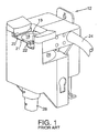
- FIGS. 1-11 there is shown a preferred embodiment of a fluid dispensing system including a fluid dispenser assembly 12 and a bottle 14 containing a quantity of a fluid that is to be dispensed.
- the fluid is provided in a concentrated form with the intention that the concentrate will be diluted with at least one other diluting fluid prior to being dispensed and used.
- the concentrate in bottle 14 may be any of a wide variety of material, such as cleaning fluids, solvents, disinfectants, insecticides, herbicides, or the like.
- the dilutant may be water or any other suitable fluid.
- dispenser assembly 12 is constructed in accordance with U.S. Patent No. 5,425,404.
- Bottle 14 of the present invention includes a valve cap 16 for controlling dispensing of concentrate from bottle 14.
- Bottle 14 with valve cap 16 cooperates with dispenser assembly 12 during use to dispense and dilute the concentrate.
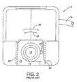
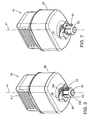
- bottle 14 is inverted as shown in FIGS. 3-11, and valve cap 16 is inserted into a chamber 18 of dispenser assembly 12.
- Chamber 18 has a generally cylindrically-shaped sidewall 19.
- Valve cap 16 generally includes a first valve part 40 (See FIG. 6) which mounts to a bottle body 60 of bottle 14 for rotation with bottle body 60 during use.
- Valve cap 16 also includes a second valve part 50 (FIG. 6) mounted to first valve part 40 for relative movement so as to open and close valve cap 16.
- a side projection or tab 52 on second valve part 50 resides in a notch 20 of dispenser assembly 12.
- bottle 14 is rotated, preferably by the user grasping bottle body 60 at end portion 417, and rotating bottle body 60 in the direction of arrow 30 (FIG. 2) to open valve cap 16
- Rotation of bottle body 60 in the direction of arrow 32 (FIG. 2) returns valve cap 16 to the closed position.
- Notch 20 constrains second valve part 50 from rotating as first valve part 40 and bottle 14 are rotated by the user.
- Rotation of bottle body 60 rotates first valve part 40 about a longitudinal axis 41 relative to second valve part 50 held from rotation by tab 52 positioned within notch 20 of dispenser assembly 12.
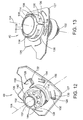
- Rotation of bottle body 60 also rotates a camming flange 42 extending from first valve part 40.
- Camming flange 42 selectively operates a dilutant valve 22 which controls the flow of dilutant from an inlet 24 to dispenser assembly 12 to enter a mixing chamber 26 of dispenser assembly 12.
- Dispenser assembly 12 includes two dilutant valves 22, each of which is linked to inlet 24 of dispenser assembly 12. Concentrate flows from within bottle 14 through valve cap 16 into mixing chamber 26 when second valve part 50 is moved relative to first valve part 40 thereby opening valve cap 16.
- Bottle body 14 is rotated back in the opposite direction to close valve cap 16, and to release camming flange 42 from engagement with each dilutant valve 22.
- Each dilutant valve 22 is spring loaded such that each dilutant valve automatically closes when bottle 14 is rotated back to the closed position. It is to be appreciated that other dispenser assemblies are possible for use with bottle 14 where the dispenser assembly holds second valve part 50 during rotation of bottle body 60, first valve part 40, and camming flange 42.
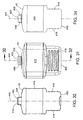
- valve cap 16 is shown both in the closed position (FIG. 6), and in the open position (FIG. 11).
- FIGS. 6 and 11 illustrate three seal regions 62, 64, and 66 for sealing an interior of bottle 14 at valve cap 16 from an exterior. Seal regions 64 and 66 are selectively opened to allow air and fluid to pass through valve cap 16 at the desired time as shown in FIG. 11. Seal regions 62, 64, and 66 will be discussed in more detail below.
- FIG. 11 illustrates the fluid flow path out of bottle 14 represented by arrows 68 through a fluid outlet 73 of valve cap 16, and the airflow path into bottle 14 represented by arrows 70 through an air inlet 75 of valve cap 16. The fluid flow path and the airflow path will be discussed in more detail below.
- valve cap 16 allows fluid outflow under the effects of gravity, since fluid outlet 73 is disposed vertically below the air inlet 75. Air from the atmosphere enters bottle 14 at air inlet 75 as fluid is dispensed. Valve cap 16 may be referred to as a "constant head valve" since the fluid level within bottle 14 above air inlet 75 does not impact fluid outflow rate. Metering of fluid flow is accomplished by providing fluid outlet 73 with a predetermined size to allow for the desired flow rate of fluid from bottle 14.
- Valve cap 16 in the preferred embodiment includes generally tubular-shaped and concentrically arranged components which rotate and longitudinally move between positions so as to open and close valve cap 16.
- the tubular portions are generally cylindrical in the preferred embodiment, although some angles and tapers may be provided to facilitate manufacture from molded materials. Steeper angles, or more conically-shaped components, are also possible wherein rotation and/or longitudinal movement of the two parts occurs with respect to a common axis, as in the preferred embodiment shown.
- Tamper resistant features are also provided with valve cap 16 in the preferred embodiment.
- the tamper resistant features prevent undesired or inadvertent dispensing by locking second valve part 50 to first valve part 40 in the closed position.
- the tamper resistant features are deactivated automatically upon use of bottle 14 and valve cap 16 with dispenser assembly 12.
- first valve part 40 and second valve part 50 snap together during assembly. Further, it is preferred that valve cap 16 snaps onto bottle 60 for further ease of assembly.
- valve cap embodiments which rely only on rotational movement to open and close the valve
- valve caps which rely only on longitudinal movement to open and close the valve.
- first valve part 40 includes an upper end 100, an opposite lower end 102, and a longitudinal central axis 104. Adjacent to upper end 100 of first valve part 40 is structure for mounting first valve part 40 to bottle body 60.
- First valve part 40 includes a tubular collar 106, and an upper tubular portion 108 inside of collar 106. Between collar 106 and tubular portion 108 is a space 110 for receiving a neck 406 of bottle body 60 (see FIG. 6).
- An O-ring 120 in space 110 further seals first valve part 40 to bottle body 60 at first seal region 62.
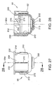
- Apertures 112 through collar 106 receive projections 408 of bottle body 60 (see also FIGS. 6, 8 and 29-34). Six apertures 112 and projections 106 are shown in the illustrated embodiment.
- first valve part 40 To facilitate alignment and attachment of first valve part 40 to bottle body 60 during assembly, a small notch 114 above each aperture 112 in collar 106 is provided for receipt of projections 408.
- a central orifice 410 of neck 406 of bottle body 60 is in fluid communication and air flow communication with first valve part 40.
- Additional projections 408 and apertures 112 are possible. Fewer projections 408 and apertures 112 are also possible, including just one of each.
- Neck 406 of bottle includes two outwardly extending flanges 413 which are received in slots 118 in collar 106.
- a chamfer 119 directs flanges 413 into the narrow portion 122 of slots 118.
- Flanges 413 and slots 118 also facilitate alignment of valve cap 16 and bottle body 60.
- first valve part 40 is provided with camming flange 42 including two camming lobes 126, 127 for engagement with each dilutant valve 22 upon rotation of camming flange 42 relative to dispenser assembly 12.
- a single lobe is also possible if desired to only operate one of dilutant valves 22.
- Tamper resistant features are provided in connection with first valve part 40. Located on camming flange 42 are a plurality of locking tabs 128 including a flexible beam 130 and a longitudinally projecting finger 132. Each finger 132 is movable longitudinally for cooperation with notches on second valve part 50. A non-functional tab 134 is provided as an optional feature, so as to further deter tampering by confusing the user as to how many locking tabs there are. Stop ring 136 is provided to limit the amount of movement of each of locking tabs 128 during use.
- the tamper resistant features of first valve part 40 will be described in more detail below in connection with the discussion of second valve part 50.
- First valve part 40 further includes a lower tubular portion 116 extending generally about longitudinal axis 104.
- Lower tubular portion 116 defines an air inlet opening or aperture 140 through the tubular wall portion 116.
- Aperture 140 forms air inlet 75 noted above for valve cap 16.
- a lower shoulder 142 on first valve part 40 defines at least one fluid opening or aperture 144.
- a plurality of apertures 144 are shown in the illustrated embodiment, spaced equally around the circular ring defining lower shoulder 142. If desired, metering can be controlled through apertures 144.
- a lower portion 146 of first valve part 40 further defines a fluid sealing region for valve cap 16.
- lower portion 146 includes a circumferential recess 148 for holding an O-ring 160 which is used to selectively seal against second valve part 50.
- O-ring 160 can also be located adjacent end surface 152. O-ring 160 seals against second valve part 50 to form third seal region 66.
- outside surface 156 of tubular portion 116 selectively seals against second valve part 50 to control air flow into and out of valve cap 16 and bottle 14.
- a circumferential groove 158 in outside surface 156 receives an O-ring 150.
- O-ring 150 seals against second valve part 50 to form second seal region 64.
- Outside surface 156 further includes projecting posts 164, for use in opening and closing valve cap 16, as will be described in greater detail below.
- second valve part 50 includes an upper end 200, an opposite lower end 202, and a longitudinal central axis 204.
- Tubular portion 206 supports projection 52 which is engaged by dispenser assembly 12 to hold second valve part 50 relative to dispenser assembly 12 while bottle 60 and first valve part 40 are rotated.
- An exterior surface 208 of tubular portion 206 further includes a plurality of spacers 210 which centrally space tubular portion 206 within chamber 18 of dispenser assembly 12.
- An interior surface 212 cooperates with O-ring 150, and lower interior surface 213 cooperates with O-ring 160 to seal valve cap 16 in the closed position.
- Extending between exterior surface 208 and interior surface 212 is aperture or opening 214.
- Two openings 214 are provided on opposite sides of tubular portion 206. One opening 214 aligns with air inlet aperture 140 to permit air flow communication from an exterior of valve cap 16 to an interior of valve cap 16 and into bottle 14 as shown in FIG. 11.
- Each opening 214 is preferably configured as an angled camming slot with camming surfaces 216 which cooperate with projecting posts 164 of first valve part 240 to cause opening and closing of valve cap 16.
- Rotation of bottle 14 and first valve part 40 relative to second valve part 50 causes posts 164 to move along camming slot 216 so as to cause longitudinal movement between the first and second valve parts 40, 50.
- O-ring 160 of first valve part 40 separates from inner sealing surface 218 at lower end 202 of second valve part 50, allowing fluid flow out of valve cap 16.
- an O-ring can be mounted in a recess in end surface 242 to provide the fluid outlet seal with an end surface 152 of first valve part.
- End surface 242 includes an aperture or opening 240 which allows for fluid outlet Opening 240 defines fluid outlet 73 noted above for valve cap 16. Opening 240 is centrally located in the preferred embodiment so as to allow fluid outflow into a central portion of dispenser assembly 12 for mixing with dilutant.
- Opening 214 as a camming slot may be constructed so that the slot is longer than the range of motion of the first and second valve parts. This prevents bottoming out of posts 164, to help reduce stress on posts 164 as might occur during use, if posts 164 were allowed to engage an end of the slot. Engagement of other structure in the dispensing system, such as camming flange 42 and dispenser assembly 12 can be used to limit the range of motion of the valve parts.
- a rim 230 Adjacent to upper end 200 of second valve part 50, a rim 230 is provided including three notches 232 for receipt of projecting fingers 132 of locking tabs 128 of first valve part 40.
- a fourth locking notch 234 is provided adjacent to non-functional tab 134 in the closed position, so as to give the appearance that a fourth locking tab needs deactivation if a user attempted to open valve cap 16 without dispenser assembly 12.
- Upper end 200 of second valve part further includes inner assembly notches 250 so as to align with posts 164 during snap fit assembly of first and second valve parts 40, 50.
- Assembly notches 250 direct posts 164 longitudinally until they are received in their respective openings 214.
- Posts 164 include a tapered outer surface 166 to fit into notches 250 to help facilitate ease of assembly.
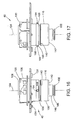
- Posts 164 in the illustrated preferred embodiment have a non-cylindrical side surface 168 (see FIG. 16). The lemon or oval shape provides increased load bearing surfaces with camming slots 216.
- Seal region 67 includes an O-ring 161 mounted in a recess like recess 158. O-ring 161 is provided for additional sealing of fluid from possibly migrating toward opening 214 in second valve part 50, instead of all the fluid exiting valve cap 16 at fluid outlet 73.
- each locking tab 128 is positioned in a locking notch 232 of second valve part 50.
- each locking tab 128 is moved or bent longitudinally upwardly due to a downward force applied by the user to bottle 14.
- Locking tabs 128 engage top surface 21 of dispenser assembly 12 so as to disengage from notches 232. In this condition, locking tabs 128 are no longer effective in limiting the ability of first valve part 40 and second valve part 50 to be rotated relative to one another.
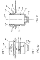
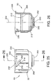
- camming slot 216 is configured with a slight circumferential slot portion 256 at the lowermost end which does not cause longitudinal separation of first and second valve parts 40, 50. (See FIGS 22 and 25).
- valve cap 16 can only likely be opened if bottle 14 is operatively engaged with dispenser assembly 12. This would prevent a user from opening the bottle separate from dispenser assembly 12, and squeezing out the contents of bottle 14, possibly over dispensing the concentrate from bottle 14. Over dispensing can be wasteful, and it can also create a more hazardous mixture having too much concentrate present.
- the tamper resistant features are also effective in preventing inadvertent dispensing such that bottle 14 will remain in the locked and closed state until the user positions bottle 14 in dispenser assembly 12, and applies downward pressure while rotating the bottle so as to open valve cap 16 to begin dispensing of the concentrate through dispenser assembly 12. Such features are useful during storage and transport.
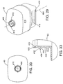
- bottle body 60 is shown including an upper closed end 400, a lower open end 402, and a longitudinal central axis 404. Adjacent to lower open end 402 is bottle neck 406 and orifice 410. Bottle body 60 snaps to valve cap 16 during assembly in the preferred embodiment.
- the plurality of projections 408 permit snap mounting of bottle body 60 to valve cap 16.
- Each projection 408 includes a ramp surface 412, and a stop shoulder 414 for engaging an inside surface of collar 106 of first valve part 40.
- Neck 406 is shown as including unequally spaced projections 408, so as to permit a limited number of ways of mounting valve cap 16 on bottle 60.
- First valve part 40 includes the unequally spaced apertures 112 for receipt of the unequally spaced projections 408.
- the flanges 413 and slots 118 in combination with the projections 408 and notches 114 results in camming flange 42 of valve cap 16 being in the proper position, and a predetermined portion of bottle body 60 facing the user during operation.
- body 60 includes a central region 416 suitable for receipt of a product label.
- Adjacent to upper closed end 400 are opposed gripping panels 418 for gripping by the hand as shown in FIGS. 3 and 7.
- end surface 420 of orifice 410 seals against O-ring 120 to form bottle and valve cap fluid tight seal 62.
- Bottle body 60 is preferably made from molded plastic, such as high density polyethylene or other moldable plastic.
- bottle 14 with valve cap 16, allows bottle 14 to be used with prior art dispenser assemblies 12 like those disclosed in U.S. Patent No. 5,425,404 and shown in FIGS. 1 and 2, or other dispenser assemblies configured to engage valve cap 16 during use.
Landscapes
- Engineering & Computer Science (AREA)
- Mechanical Engineering (AREA)
- Closures For Containers (AREA)
- Devices For Dispensing Beverages (AREA)
- Containers And Packaging Bodies Having A Special Means To Remove Contents (AREA)
- Fluid-Driven Valves (AREA)
Applications Claiming Priority (3)
| Application Number | Priority Date | Filing Date | Title |
|---|---|---|---|
| US09/422,752 US6223791B1 (en) | 1999-10-21 | 1999-10-21 | Gravity feed fluid dispensing valve |
| US422752 | 1999-10-21 | ||
| PCT/US2000/003027 WO2001028914A1 (en) | 1999-10-21 | 2000-02-04 | Gravity feed fluid dispensing valve |
Publications (2)
| Publication Number | Publication Date |
|---|---|
| EP1222135A1 EP1222135A1 (en) | 2002-07-17 |
| EP1222135B1 true EP1222135B1 (en) | 2004-08-25 |
Family
ID=23676212
Family Applications (1)
| Application Number | Title | Priority Date | Filing Date |
|---|---|---|---|
| EP00910088A Expired - Lifetime EP1222135B1 (en) | 1999-10-21 | 2000-02-04 | Gravity feed fluid dispensing valve |
Country Status (13)
| Country | Link |
|---|---|
| US (2) | US6223791B1 (enExample) |
| EP (1) | EP1222135B1 (enExample) |
| JP (1) | JP4464025B2 (enExample) |
| KR (1) | KR100735644B1 (enExample) |
| CN (1) | CN1317179C (enExample) |
| AT (1) | ATE274467T1 (enExample) |
| AU (1) | AU781288B2 (enExample) |
| BR (1) | BR0014891B1 (enExample) |
| CA (2) | CA2689039A1 (enExample) |
| DE (1) | DE60013312T2 (enExample) |
| MX (1) | MXPA02003955A (enExample) |
| TW (1) | TW469257B (enExample) |
| WO (1) | WO2001028914A1 (enExample) |
Cited By (2)
| Publication number | Priority date | Publication date | Assignee | Title |
|---|---|---|---|---|
| WO2016106023A1 (en) * | 2014-12-24 | 2016-06-30 | Drink Saporé Inc. | Liquid container apparatus |
| US11014801B2 (en) | 2017-11-10 | 2021-05-25 | Pentair Flow Technologies, Llc | Coupler for use in a closed transfer system |
Families Citing this family (32)
| Publication number | Priority date | Publication date | Assignee | Title |
|---|---|---|---|---|
| US6223791B1 (en) * | 1999-10-21 | 2001-05-01 | 3M Innovative Properties Company | Gravity feed fluid dispensing valve |
| US6443189B1 (en) * | 2001-02-21 | 2002-09-03 | The Coca-Cola Company | Valve assembly for filling containers |
| AT500874B1 (de) | 2004-03-05 | 2006-11-15 | Hagleitner Hans Georg | Ausgabeventil |
| US7546857B2 (en) | 2004-05-06 | 2009-06-16 | Colder Products Company | Connect/disconnect coupling for a container |
| US7621426B2 (en) * | 2004-12-15 | 2009-11-24 | Joseph Kanfer | Electronically keyed dispensing systems and related methods utilizing near field frequency response |
| US7753087B2 (en) * | 2005-10-19 | 2010-07-13 | Kutol Products Company, Inc. | Product dispensing system |
| EP1806314A1 (en) * | 2006-01-09 | 2007-07-11 | Nestec S.A. | Device for dispensing a beverage with a controlled air inlet, and method therefor |
| EP2051928A2 (en) * | 2006-07-11 | 2009-04-29 | Colder Products Company | Connect/disconnect coupling for a container |
| EP2916054A2 (fr) * | 2007-03-28 | 2015-09-09 | Fillon Technologies | Valve de dosage |
| US8584702B2 (en) * | 2007-11-07 | 2013-11-19 | Cummins Filtration Ip, Inc. | Apparatus, system, and method for a self-venting drain valve |
| CA2777721C (en) * | 2009-11-25 | 2018-01-16 | Baxter International Inc. | Drip chamber with flow control |
| US8579162B2 (en) * | 2010-04-14 | 2013-11-12 | 3M Innovative Properties Company | Enclosure for use with a gravity fed fluid dispensing system |
| KR101008800B1 (ko) * | 2010-09-03 | 2011-01-14 | 오성택 | 조사료용 곡물수확기 |
| WO2013126663A1 (en) * | 2012-02-24 | 2013-08-29 | The Coca-Cola Company | Mechanical dispensing system |
| GB2531176B (en) | 2013-03-15 | 2017-10-18 | Bissell Homecare Inc | Fluid delivery system |
| AT515274B1 (de) | 2013-12-20 | 2017-10-15 | Hans Georg Hagleitner | Behälter |
| US9873604B2 (en) * | 2015-03-06 | 2018-01-23 | Taphandles Llc | Adjustment mechanism for a beverage tap handle |
| US12128460B2 (en) * | 2021-09-09 | 2024-10-29 | Pentair Flow Technologies, Llc | Apparatus to direct flow of fluid |
| US11647860B1 (en) | 2022-05-13 | 2023-05-16 | Sharkninja Operating Llc | Flavored beverage carbonation system |
| US12213617B2 (en) | 2022-05-13 | 2025-02-04 | Sharkninja Operating Llc | Flavored beverage carbonation process |
| US11751585B1 (en) | 2022-05-13 | 2023-09-12 | Sharkninja Operating Llc | Flavored beverage carbonation system |
| US12096880B2 (en) * | 2022-05-13 | 2024-09-24 | Sharkninja Operating Llc | Flavorant for beverage carbonation system |
| US11634314B1 (en) | 2022-11-17 | 2023-04-25 | Sharkninja Operating Llc | Dosing accuracy |
| US11738988B1 (en) | 2022-11-17 | 2023-08-29 | Sharkninja Operating Llc | Ingredient container valve control |
| US12103840B2 (en) | 2022-11-17 | 2024-10-01 | Sharkninja Operating Llc | Ingredient container with sealing valve |
| US11745996B1 (en) | 2022-11-17 | 2023-09-05 | Sharkninja Operating Llc | Ingredient containers for use with beverage dispensers |
| US12084334B2 (en) | 2022-11-17 | 2024-09-10 | Sharkninja Operating Llc | Ingredient container |
| USD1091308S1 (en) | 2022-12-23 | 2025-09-02 | Sharkninja Operating Llc | Ingredient container |
| USD1092208S1 (en) | 2022-12-23 | 2025-09-09 | Sharkninja Operating Llc | Cap of ingredient container |
| US12116257B1 (en) | 2023-03-22 | 2024-10-15 | Sharkninja Operating Llc | Adapter for beverage dispenser |
| US11871867B1 (en) | 2023-03-22 | 2024-01-16 | Sharkninja Operating Llc | Additive container with bottom cover |
| US11925287B1 (en) | 2023-03-22 | 2024-03-12 | Sharkninja Operating Llc | Additive container with inlet tube |
Family Cites Families (169)
| Publication number | Priority date | Publication date | Assignee | Title |
|---|---|---|---|---|
| US500260A (en) | 1893-06-27 | Pour-out or discharger for bottles | ||
| US232362A (en) | 1880-09-21 | Stephen s | ||
| US1307828A (en) | 1919-06-24 | Absignoe | ||
| US585327A (en) | 1897-06-29 | Faucet | ||
| US273831A (en) | 1883-03-13 | Philip ely | ||
| US251923A (en) | 1882-01-03 | Bottle-stopper | ||
| US147272A (en) | 1874-02-10 | Improvement in oil-cans | ||
| DE102353C (enExample) * | ||||
| US1310405A (en) | 1919-07-15 | Pour-out for bottles | ||
| US76483A (en) | 1868-04-07 | Improvement in oil-cans | ||
| US196437A (en) | 1877-10-23 | Improvement in vent-faucets for bottles | ||
| US539460A (en) | 1895-05-21 | Oil-can and pou ring-faucet therefor | ||
| US654016A (en) | 1899-12-01 | 1900-07-17 | Samuel C Miller | Bottle-filling machine. |
| US694477A (en) | 1901-03-11 | 1902-03-04 | Frank E Howland | Valve. |
| US705160A (en) | 1902-03-04 | 1902-07-22 | John Albert Swanson | Oil-can spout. |
| US815158A (en) | 1905-09-16 | 1906-03-13 | Noah Carpenter | Oil-flask. |
| US857056A (en) | 1906-11-10 | 1907-06-18 | William Ellis Harmon | Oil-can. |
| US1026145A (en) | 1911-02-15 | 1912-05-14 | Philo M Blackman | Filling apparatus for liquid-receptacles. |
| US1054146A (en) | 1911-11-15 | 1913-02-25 | Mathew Andrew Smirle | Spigot. |
| US1221350A (en) | 1914-10-09 | 1917-04-03 | Sanitary Spout Company | Closure for bottles, jars, and other vessels. |
| US1519347A (en) | 1915-03-10 | 1924-12-16 | W E Warwick | Controlling device for liquid receptacles |
| US1265381A (en) | 1915-10-04 | 1918-05-07 | Thomas T Ramey | Quick-emptying funnel. |
| US1278764A (en) | 1917-01-22 | 1918-09-10 | Oscar F Seiler | Oil-can attachment. |
| US1368703A (en) | 1919-10-04 | 1921-02-15 | Czerny Stanislaus | Bottle-closure |
| US1581072A (en) | 1925-07-17 | 1926-04-13 | Lumsden George Henry Charles | Closure for water bottles and the like |
| US1676711A (en) | 1926-09-27 | 1928-07-10 | Edward A Reap | Can |
| US1913393A (en) | 1931-07-25 | 1933-06-13 | Albert H Jones | Pouring stopper for ink bottles and the like |
| GB428722A (en) | 1933-03-17 | 1935-05-17 | Alberto Louis Maggenti | Improvements relating to devices for tapping containers |
| US2036310A (en) | 1933-12-01 | 1936-04-07 | Edmund Rogers | Device for measuring and dispensing liquids |
| US2165825A (en) | 1935-01-23 | 1939-07-11 | Bultzingslowen Bruno Von | Container and closure for same |
| US2051513A (en) | 1935-04-01 | 1936-08-18 | Bingham Richard | Dispensing cap for collapsible tubes |
| US2165570A (en) | 1938-04-02 | 1939-07-11 | Olson John | Liquid dispenser |
| US2364400A (en) | 1940-06-21 | 1944-12-05 | Crown Cork & Seal Co | Apparatus for filling |
| US2239921A (en) | 1941-02-24 | 1941-04-29 | Jr Joseph M Majewski | Liquid dispensing device |
| US2328110A (en) | 1941-03-14 | 1943-08-31 | Amp Corp | Beverage dispensing apparatus |
| US2401914A (en) | 1942-10-17 | 1946-06-11 | Pietro Carmelo V Di | Mixing faucet |
| US2543390A (en) | 1944-05-17 | 1951-02-27 | Liquid Carbonic Corp | Draft arm for carbonated beverages |
| GB635966A (en) | 1945-01-01 | 1950-04-19 | Dole Valve Co | Improvements in or relating to a drink dispenser |
| US2537119A (en) | 1945-02-02 | 1951-01-09 | Dole Valve Co | Liquid dispenser for carbonated beverages |
| US2408664A (en) | 1945-05-17 | 1946-10-01 | Ginger Cola Dispenser Inc | Mixing faucet for beverages |
| US2463922A (en) | 1946-02-15 | 1949-03-08 | William E Turner | Liquid dispenser with receptacle operated outlet valve |
| US2500199A (en) | 1946-04-03 | 1950-03-14 | Baxter Laboratories Inc | Dispensing of liquids |
| US2558700A (en) | 1946-10-30 | 1951-06-26 | Marion L J Lambert | Carbonated beverage dispensing valve |
| US2520003A (en) | 1947-01-29 | 1950-08-22 | West Disinfecting Co | Dispenser with supply container locking device |
| GB659764A (en) | 1947-12-31 | 1951-10-24 | Spacarb Inc | Improvements in or relating to a beverage mixing device |
| US2542350A (en) | 1948-09-30 | 1951-02-20 | Harry N Peavy | Snap-on dispensing closure for collapsible tubes |
| US2698703A (en) | 1950-06-26 | 1955-01-04 | Leo M Harvey | Liquid dispenser delivering measured quantities |
| US2724535A (en) | 1951-10-04 | 1955-11-22 | Crown Cork & Seal Co | Filling valve for apparatus for filling containers with liquid |
| US2749096A (en) | 1953-02-25 | 1956-06-05 | Cole Albert | Beverage dispensing apparatus |
| US2754999A (en) | 1953-05-08 | 1956-07-17 | Dole Valve Co | Throw-away type dispenser |
| US2718985A (en) | 1954-08-04 | 1955-09-27 | Monitor Process Corp | Milk dispenser |
| US2778545A (en) | 1954-09-22 | 1957-01-22 | Sapient Sales Co Inc | Expandable stopper with spout |
| US2785833A (en) | 1954-11-22 | 1957-03-19 | Dole Valve Co | Dispenser for concentrates |
| US2841313A (en) | 1955-03-10 | 1958-07-01 | Jr Richard W Beall | Self venting dispensing spout |
| US2880912A (en) | 1955-04-18 | 1959-04-07 | Russel E Fisher | System for dispensing flavored beverages |
| US2765956A (en) | 1955-07-25 | 1956-10-09 | Norman E Schmidtke | Dispensing means |
| US2857084A (en) | 1956-05-09 | 1958-10-21 | Melikian Inc Rudd | Constant head device |
| DE1727181U (de) | 1956-05-16 | 1956-07-26 | Kautex Werke Gmbh | Flaschen- oder beutelfoermiger und mit einer verschlussverschraubung versehener behaelter aus thermoplastischem kunststoff, insbesondere aus polyvinylchlorid, fuer pastenfoermiges bohnerwachs od. dgl. |
| FR1174882A (fr) | 1957-05-09 | 1959-03-17 | Dispositif de bouchage étanche de tubes distributeurs de produits pâteux, pulvérulents, etc. ou autres articles analogues permettant l'ouverture ou la fermeture par rotation d'un bouchon | |
| US2969896A (en) | 1957-10-28 | 1961-01-31 | Braun Co W | Cap or closure for containers or tubes |
| AT202512B (de) | 1958-01-14 | 1959-03-10 | Johann Berauer | Tubenverschluß |
| US3074700A (en) | 1959-12-07 | 1963-01-22 | Jr William C Buttner | Carbonating apparatus |
| US3086683A (en) | 1960-02-24 | 1963-04-23 | Marlin N Loper | Liquid dispensing device |
| US2989243A (en) | 1960-04-19 | 1961-06-20 | Turak Anthony | Carbonated liquid valve |
| DE1136906B (de) | 1961-12-20 | 1962-09-20 | Hedwin Corp | Entnahmegeraet fuer durchstossbare Fluessigkeitsbehaelter |
| US3326417A (en) | 1962-07-05 | 1967-06-20 | Techomatic Ind Inc | Automatic liquid dispensing machine |
| US3142320A (en) | 1962-07-30 | 1964-07-28 | Theodore M Olson | Double tube dispensing device |
| US3143255A (en) | 1963-01-28 | 1964-08-04 | Harry R Leeds | Captive plug dispensing closure |
| FR1364608A (fr) | 1963-03-04 | 1964-06-26 | Moyens nouveaux pour obtenir des boissons avec des cartouches pré-conditionnées | |
| US3258166A (en) | 1963-11-19 | 1966-06-28 | Dagma G M B H & Co | Dispenser for liquids |
| GB1049118A (en) | 1964-04-14 | 1966-11-23 | Graham Enock Mfg Company Ltd | Apparatus for filling containers with liquid |
| US3325844A (en) | 1964-07-27 | 1967-06-20 | Electrolux Corp | End closure arrangement for dispensing foamable liquids |
| US3292822A (en) | 1964-09-11 | 1966-12-20 | Thomas E Crowder | Self-contained drink dispensing device |
| US3225970A (en) | 1964-10-02 | 1965-12-28 | William J Rooney | Container closure with integral spout |
| US3225950A (en) | 1965-03-22 | 1965-12-28 | Grace W R & Co | Plastic bottle |
| US3341073A (en) | 1965-04-14 | 1967-09-12 | Milton J Arps | Metering and dispensing apparatus |
| US3455332A (en) | 1965-10-18 | 1969-07-15 | Cornelius Co | Post-mix valve |
| US3357605A (en) | 1966-05-09 | 1967-12-12 | Formold Plastics Inc | Dispensing closure |
| US3396871A (en) | 1966-07-15 | 1968-08-13 | Mccann S Engineering & Mfg Co | Beverage dispensing unit |
| US3536500A (en) | 1966-09-23 | 1970-10-27 | Dow Chemical Co | Packaged food |
| US3401850A (en) | 1966-12-06 | 1968-09-17 | Electrolux Corp | Check valve for vent hole of a container |
| US3520451A (en) | 1967-05-17 | 1970-07-14 | Hiroshi Ashizawa | Sanitary milk dispenser |
| US3384276A (en) | 1967-05-29 | 1968-05-21 | Robert F. Henningfield | Valved dispenser in combination with an aerating device for a bottled liquid |
| US3439843A (en) | 1967-08-14 | 1969-04-22 | Diamond Int Corp | Liquid dispenser having a closure cap |
| SE378409B (enExample) | 1968-12-18 | 1975-09-01 | Kantor Int Sa | |
| AT295309B (de) | 1969-02-21 | 1971-12-27 | Imd | Vorrichtung zur Herstellung von kohlensäurehältigen Getränken |
| DE1932935A1 (de) | 1969-06-28 | 1971-01-07 | Alexander Kueckens | Vorrichtung zur Herstellung eines trinkfertigen Limonaden- oder Fruchtsaftgetraenkes mit und ohne Kohlensaeure aus einem durch seinen hohen Zuckeranteil,mindestens ueber 60 Brix-Grade,selbstkonservierenden Sirup oder Konzentrat durch Vermischung mit beispielsweise Wasser |
| US3606096A (en) | 1969-09-30 | 1971-09-20 | Huffman Mfg Co | Liquid dispensing device |
| US3685694A (en) | 1969-12-18 | 1972-08-22 | Yan Nell Corp | Liquid dispenser plastic bottle and receptacle with piercing units |
| US3658216A (en) | 1970-02-27 | 1972-04-25 | Gilbert Schwartzman | Metering and discharge device |
| US3664550A (en) | 1970-05-22 | 1972-05-23 | Olen E Carothers | Dispensing system for beverages and other liquids |
| US3690520A (en) | 1970-06-26 | 1972-09-12 | Samuel E Sarris | Push-pull container and cap assembly |
| FR2147579A5 (enExample) | 1971-07-24 | 1973-03-09 | Dagma Gmbh Et Co | |
| US3782610A (en) | 1972-07-06 | 1974-01-01 | L Gilbert | Bottle valve |
| US3887116A (en) | 1972-09-01 | 1975-06-03 | Shiseido Co Ltd | Receptacle for liquid material |
| US3843021A (en) | 1972-10-02 | 1974-10-22 | Corco Inc | Disposable reservoir package for liquid-dispenser having float-operated valve |
| US3800826A (en) | 1972-12-26 | 1974-04-02 | Mc Cann S Eng & Mfg Co | Soft drink dispenser disconnect assembly |
| US3941171A (en) | 1973-07-05 | 1976-03-02 | Ims Limited | Fluid transfer device |
| US3834596A (en) | 1973-07-11 | 1974-09-10 | Mennen Co | Bottle-closure structure |
| US3986642A (en) | 1974-10-02 | 1976-10-19 | All State Vending Equipment, Inc. | Adjustable nozzle assembly for dispensing liquid |
| US3991219A (en) | 1974-12-26 | 1976-11-09 | Dagma Deutsche Automaten Und Getrankemaschinen G.M.B.H. & Co. | Method for mixing a carbonated beverage |
| DE2608503C3 (de) | 1975-03-21 | 1981-01-29 | Dagma Deutsche Automaten- Und Getraenkemaschinen Gmbh & Co Kg, 2067 Reinfeld | Verfahren und Gerät zum Herstellen von Getränken unter dosiertem Abgeben und Mischen von Wasser und selbstkonservierenden Konzentraten oder Sirupen hoher Viskosität |
| NL181189C (nl) | 1975-03-21 | Dagma Gmbh & Co | Inrichting voor het bereiden van een koolzuurhoudende drank. | |
| US4011733A (en) | 1975-07-29 | 1977-03-15 | Dagma Gmbh & Co. | Apparatus and process for carbonating liquids |
| USRE32231E (en) | 1975-10-06 | 1986-08-26 | DAGMA Deutsche Automaten-und Getrakemaschinen-Gesellschaft mit beschrankter Haftung & Co. | Container for metered dispensing of liquid |
| DE2544671C3 (de) | 1975-10-06 | 1979-05-17 | Dagma Deutsche Automaten- Und Getraenkemaschinen-Gesellschaft Mbh & Co, 2067 Reinfeld | Behälter zur dosierten Abgabe von Flüssigkeiten |
| DE2557961C3 (de) | 1975-12-22 | 1978-08-31 | Siemens Ag, 1000 Berlin Und 8000 Muenchen | Flüssigkeitspumpsystem für einen Flüssigkeitsstrahlschreiber |
| US4121507A (en) | 1976-03-17 | 1978-10-24 | Dagma Gmbh & Co. Deutsche Automaten-Und Getranke Maschinen | Apparatus for mixing a carbonated beverage |
| IT1074996B (it) | 1976-12-07 | 1985-04-22 | Wienser Alfredo | Perfezionamento ai distributori di sciroppi in quantita dosate la preparazione di bevande |
| US4125334A (en) | 1977-11-17 | 1978-11-14 | Coal Industry (Patents) Limited | Apparatus for mixing two flowable substances |
| US4113129A (en) | 1978-01-05 | 1978-09-12 | Respiratory Care, Inc. | Container for sterile liquids |
| US4141461A (en) | 1978-01-31 | 1979-02-27 | Lachance Ernest J | Secure bottle with novel cap |
| US4176694A (en) | 1978-03-27 | 1979-12-04 | Donald R. Dickerson | Automatic shutoff liquid dispensing valve |
| US4270673A (en) | 1978-07-24 | 1981-06-02 | Alco Foodservice Equipment Company | Electric gravity dispensing valve |
| US4293081A (en) | 1978-08-03 | 1981-10-06 | Dagma Deutsche Automaten Und Getrankemaschinen Gmbh & Co. Kg | Method and device for metered dispensing of liquids, in particular concentrates or syrups, for the production of beverages |
| ATE3916T1 (de) | 1978-10-24 | 1983-07-15 | Vgl Industries Limited | Verbesserungen an ingredienzienbehaeltern fuer verkaufsautomaten. |
| GB2037255B (en) | 1978-12-12 | 1982-10-20 | Dagma Gmbh & Co | Metered dispensing of liquid |
| US4248335A (en) | 1979-01-25 | 1981-02-03 | Mcquay-Perfex Inc. | Key-operated actuator |
| GB2101090B (en) | 1979-02-28 | 1983-08-17 | Cadbury Schweppes Ltd | Dispensing container |
| US4523697A (en) | 1979-07-11 | 1985-06-18 | Cadbury Schweppes Limited | Liquid dispensing package |
| DE2932558C2 (de) | 1979-08-10 | 1983-03-24 | DAGMA Deutsche Automaten- und Getränkemaschinen GmbH & Co KG, 2067 Reinfeld | Vorrichtung zum genauen Dosieren von Fluids schwankender Viskosität, insb. stark viskosen Flüssigkeiten |
| US4408701A (en) | 1980-04-16 | 1983-10-11 | Cadbury Schweppes Plc | Liquid dispensing valve |
| US4555371A (en) | 1980-04-16 | 1985-11-26 | Cadbury Schweppes, Plc | Carbonator for a beverage dispenser |
| US4355735A (en) | 1980-07-14 | 1982-10-26 | Tannetics, Inc. | Valving mechanism for beverage dispensing device |
| US4363424A (en) | 1980-10-23 | 1982-12-14 | Cadbury Schweppes Pcl | Quick coupling device for a gas pressurization system |
| US4344459A (en) | 1980-11-03 | 1982-08-17 | Nelson Walter R | Flow control device employing elastomeric element |
| US4637439A (en) | 1981-02-09 | 1987-01-20 | Cadbury Schweppes, Plc | Mini-regulator valve assembly |
| DE3131650C2 (de) | 1981-03-26 | 1985-02-14 | DAGMA Deutsche Automaten- und Getränkemaschinen GmbH & Co KG, 2067 Reinfeld | Vorrichtung zum Abgeben von viskosen Konzentraten veränderlicher Viskosität in genau dosierbaren Mengen von veränderlich einstellbarem Volumen, insb. für Getränkeautomaten |
| US4421804A (en) | 1981-09-11 | 1983-12-20 | Japan Crown Cork Co., Ltd. | Bottle for carbonated drink |
| US4457343A (en) | 1982-09-20 | 1984-07-03 | Eaton Corporation | Flow washer |
| US4488584A (en) | 1982-09-30 | 1984-12-18 | Bomatic, Inc. | Drainer container and funnel |
| DK152200C (da) | 1982-11-11 | 1988-06-27 | Hartwall Ltd | Anlaeg til aktivering af et doseringsapparat til udskaenkning af forudbestemte maengder af en drikkevare fra en flaske |
| US4570830A (en) | 1983-06-28 | 1986-02-18 | Cadbury Schweppes, Plc | Gravity dispenser |
| US4564483A (en) | 1983-11-10 | 1986-01-14 | Cadbury Schweppes, Plc | Method and apparatus for batch carbonating |
| US4624395A (en) | 1984-05-11 | 1986-11-25 | Lykes Pasco Packing Co. | Hot beverage dispensing machine |
| US4613063A (en) | 1985-01-07 | 1986-09-23 | Sunbeam Plastics Corporation | Dispensing package |
| EP0356829B1 (en) | 1985-04-17 | 1993-11-24 | Yoshino Kogyosho Co., Ltd. | Biaxial-orientation blow-moulded bottle-shaped container |
| US5222615A (en) | 1985-07-30 | 1993-06-29 | Yoshino Kogyosho Co., Ltd. | Container having support structure in its bottom section |
| US5251789A (en) | 1985-11-20 | 1993-10-12 | Cadbury Schweppes, Plc | In-home drink dispenser |
| US4712713A (en) | 1985-11-20 | 1987-12-15 | Cadbury Schweppes, Plc | Gas cylinder coupling and weighting mechanism for a carbonated drink dispenser |
| USD298514S (en) | 1985-11-20 | 1988-11-15 | Cadbury Schweppes, Plc | Syrup container or similar article |
| US4691822A (en) | 1986-04-07 | 1987-09-08 | Malancon Jr Irvin P | Container and holder for dispensing baking soda |
| US4993565A (en) | 1986-04-14 | 1991-02-19 | Yoshino Kogyosho Co., Ltd. | Biaxial-orientation blow-molded bottle-shaped container having opposed recesses and grooves for stable gripping and anti-buckling stiffness |
| USD304552S (en) | 1986-10-30 | 1989-11-14 | Jerome Lippman | Container for liquids |
| US4805808A (en) | 1987-02-26 | 1989-02-21 | Bmr Investments, Inc. | Container and liquid dispenser |
| US4802610A (en) | 1987-01-05 | 1989-02-07 | The Dow Chemical Company | Pour spout |
| US4911212A (en) | 1987-07-06 | 1990-03-27 | Burton John W | Bottle filling device |
| GB8717407D0 (en) | 1987-07-23 | 1987-08-26 | Diversey Corp | Dispenser |
| US4805793A (en) | 1987-10-23 | 1989-02-21 | Pioneer/Eclipse Corporation | Stackable bottle |
| US4865211A (en) | 1988-03-04 | 1989-09-12 | Hollingsworth Elmont E | Collapsible article |
| JPH03501647A (ja) | 1988-07-01 | 1991-04-11 | スィブジェ ソシエテ アノニム | 安全ライター |
| US4874023A (en) | 1988-09-30 | 1989-10-17 | Liqui-Box Corporation | Decap dispensing system for water cooler bottles |
| US5123554A (en) | 1988-10-31 | 1992-06-23 | Abbott Laboratories | Retortable plastic containers |
| CA2025352A1 (en) * | 1989-01-18 | 1990-07-19 | William R. Scholle | Method and apparatus for dispensing liquid |
| US5067622A (en) | 1989-11-13 | 1991-11-26 | Van Dorn Company | Pet container for hot filled applications |
| US5042698A (en) | 1990-03-02 | 1991-08-27 | Eric Fessell | Easy pour spout |
| USD342176S (en) | 1990-05-01 | 1993-12-14 | Steiner Company, Inc. | Refill container for a liquid dispenser |
| AU112760S (en) | 1990-06-08 | 1991-11-06 | Bentfield B V | Liquid dispenser |
| USD331516S (en) | 1990-08-24 | 1992-12-08 | James River Corporation | Liquid reservoir for installation in a dispensing unit |
| USD330483S (en) | 1990-09-24 | 1992-10-27 | The Coca-Cola Company | Container |
| US5141121A (en) | 1991-03-18 | 1992-08-25 | Hoover Universal, Inc. | Hot fill plastic container with invertible vacuum collapse surfaces in the hand grips |
| US5224614A (en) | 1992-02-07 | 1993-07-06 | The Procter & Gamble Company | Non-handled lightweight plastic bottle with a substantially rigid grip design to facilitate pouring without loss of control |
| USD369110S (en) | 1993-04-20 | 1996-04-23 | Minnesota Mining And Manufacturing Company | Bottle |
| US5425404A (en) * | 1993-04-20 | 1995-06-20 | Minnesota Mining And Manufacturing Company | Gravity feed fluid dispensing system |
| US5435451A (en) | 1993-04-20 | 1995-07-25 | Minnesota Mining And Manufacturing Company | Bottle for containing a fluid |
| US5715877A (en) | 1996-10-01 | 1998-02-10 | Champion Chemical Co. Of Calif., Inc. | Solution dilution assembly |
| EP1346944B1 (en) * | 1997-10-08 | 2006-01-18 | Minnesota Mining And Manufacturing Company | Gravity feed fluid dispensing valve cap |
| AU6948998A (en) * | 1997-12-03 | 1999-06-16 | Minnesota Mining And Manufacturing Company | Gravity feed fluid dispensing system including shut-off assembly and lock assembly |
| US6223791B1 (en) * | 1999-10-21 | 2001-05-01 | 3M Innovative Properties Company | Gravity feed fluid dispensing valve |
-
1999
- 1999-10-21 US US09/422,752 patent/US6223791B1/en not_active Expired - Lifetime
-
2000
- 2000-02-04 KR KR1020027005034A patent/KR100735644B1/ko not_active Expired - Fee Related
- 2000-02-04 CA CA002689039A patent/CA2689039A1/en not_active Abandoned
- 2000-02-04 MX MXPA02003955A patent/MXPA02003955A/es active IP Right Grant
- 2000-02-04 AT AT00910088T patent/ATE274467T1/de not_active IP Right Cessation
- 2000-02-04 JP JP2001531712A patent/JP4464025B2/ja not_active Expired - Fee Related
- 2000-02-04 BR BRPI0014891-1A patent/BR0014891B1/pt not_active IP Right Cessation
- 2000-02-04 DE DE60013312T patent/DE60013312T2/de not_active Expired - Lifetime
- 2000-02-04 AU AU32237/00A patent/AU781288B2/en not_active Ceased
- 2000-02-04 CN CNB008146349A patent/CN1317179C/zh not_active Expired - Fee Related
- 2000-02-04 EP EP00910088A patent/EP1222135B1/en not_active Expired - Lifetime
- 2000-02-04 CA CA2388539A patent/CA2388539C/en not_active Expired - Fee Related
- 2000-02-04 WO PCT/US2000/003027 patent/WO2001028914A1/en not_active Ceased
- 2000-10-16 TW TW089121592A patent/TW469257B/zh not_active IP Right Cessation
-
2001
- 2001-03-01 US US09/797,322 patent/US6354346B2/en not_active Expired - Lifetime
Cited By (3)
| Publication number | Priority date | Publication date | Assignee | Title |
|---|---|---|---|---|
| WO2016106023A1 (en) * | 2014-12-24 | 2016-06-30 | Drink Saporé Inc. | Liquid container apparatus |
| US11014801B2 (en) | 2017-11-10 | 2021-05-25 | Pentair Flow Technologies, Llc | Coupler for use in a closed transfer system |
| US11214479B2 (en) | 2017-11-10 | 2022-01-04 | Pentair Flow Technologies, Llc | Probe assembly for use in a closed transfer system |
Also Published As
| Publication number | Publication date |
|---|---|
| CA2689039A1 (en) | 2001-04-26 |
| CA2388539C (en) | 2010-08-03 |
| JP4464025B2 (ja) | 2010-05-19 |
| US20010008152A1 (en) | 2001-07-19 |
| DE60013312T2 (de) | 2005-09-22 |
| MXPA02003955A (es) | 2002-12-13 |
| US6354346B2 (en) | 2002-03-12 |
| WO2001028914A1 (en) | 2001-04-26 |
| EP1222135A1 (en) | 2002-07-17 |
| ATE274467T1 (de) | 2004-09-15 |
| CN1317179C (zh) | 2007-05-23 |
| CN1382103A (zh) | 2002-11-27 |
| DE60013312D1 (de) | 2004-09-30 |
| AU3223700A (en) | 2001-04-30 |
| KR20020059632A (ko) | 2002-07-13 |
| JP2003512264A (ja) | 2003-04-02 |
| BR0014891B1 (pt) | 2011-02-22 |
| KR100735644B1 (ko) | 2007-07-16 |
| TW469257B (en) | 2001-12-21 |
| BR0014891A (pt) | 2002-07-02 |
| US6223791B1 (en) | 2001-05-01 |
| CA2388539A1 (en) | 2001-04-26 |
| AU781288B2 (en) | 2005-05-12 |
Similar Documents
| Publication | Publication Date | Title |
|---|---|---|
| EP1222135B1 (en) | Gravity feed fluid dispensing valve | |
| US6450214B1 (en) | Gravity feed fluid dispensing valve | |
| US6367521B2 (en) | Gravity feed fluid dispensing valve | |
| US5213265A (en) | Single valve aspiration type sprayer | |
| US7073546B2 (en) | Valve assembly for use with containers in a closed application system | |
| KR100287608B1 (ko) | 중력 공급식 유체 분배 장치 | |
| US5100059A (en) | Single valve aspiration type sprayer | |
| EP1419014B1 (en) | Safety closure for a container | |
| AU3554499A (en) | Controlled product dispensing system | |
| US6321948B1 (en) | Tap and valve assembly | |
| US7434707B2 (en) | Childproof attachment for a dispenser | |
| MXPA00003299A (en) | Gravity feed fluid dispensing valve | |
| WO1999028045A2 (en) | Gravity feed fluid dispensing system including shut-off assembly and lock assembly |
Legal Events
| Date | Code | Title | Description |
|---|---|---|---|
| PUAI | Public reference made under article 153(3) epc to a published international application that has entered the european phase |
Free format text: ORIGINAL CODE: 0009012 |
|
| 17P | Request for examination filed |
Effective date: 20020422 |
|
| AK | Designated contracting states |
Kind code of ref document: A1 Designated state(s): AT BE CH CY DE DK ES FI FR GB GR IE IT LI LU NL |
|
| 17Q | First examination report despatched |
Effective date: 20021202 |
|
| GRAP | Despatch of communication of intention to grant a patent |
Free format text: ORIGINAL CODE: EPIDOSNIGR1 |
|
| GRAS | Grant fee paid |
Free format text: ORIGINAL CODE: EPIDOSNIGR3 |
|
| GRAA | (expected) grant |
Free format text: ORIGINAL CODE: 0009210 |
|
| AK | Designated contracting states |
Kind code of ref document: B1 Designated state(s): AT BE CH CY DE DK ES FI FR GB GR IE IT LI LU NL PT SE |
|
| PG25 | Lapsed in a contracting state [announced via postgrant information from national office to epo] |
Ref country code: IT Free format text: LAPSE BECAUSE OF FAILURE TO SUBMIT A TRANSLATION OF THE DESCRIPTION OR TO PAY THE FEE WITHIN THE PRESCRIBED TIME-LIMIT;WARNING: LAPSES OF ITALIAN PATENTS WITH EFFECTIVE DATE BEFORE 2007 MAY HAVE OCCURRED AT ANY TIME BEFORE 2007. THE CORRECT EFFECTIVE DATE MAY BE DIFFERENT FROM THE ONE RECORDED. Effective date: 20040825 Ref country code: LI Free format text: LAPSE BECAUSE OF FAILURE TO SUBMIT A TRANSLATION OF THE DESCRIPTION OR TO PAY THE FEE WITHIN THE PRESCRIBED TIME-LIMIT Effective date: 20040825 Ref country code: NL Free format text: LAPSE BECAUSE OF FAILURE TO SUBMIT A TRANSLATION OF THE DESCRIPTION OR TO PAY THE FEE WITHIN THE PRESCRIBED TIME-LIMIT Effective date: 20040825 Ref country code: AT Free format text: LAPSE BECAUSE OF FAILURE TO SUBMIT A TRANSLATION OF THE DESCRIPTION OR TO PAY THE FEE WITHIN THE PRESCRIBED TIME-LIMIT Effective date: 20040825 Ref country code: BE Free format text: LAPSE BECAUSE OF FAILURE TO SUBMIT A TRANSLATION OF THE DESCRIPTION OR TO PAY THE FEE WITHIN THE PRESCRIBED TIME-LIMIT Effective date: 20040825 Ref country code: CH Free format text: LAPSE BECAUSE OF FAILURE TO SUBMIT A TRANSLATION OF THE DESCRIPTION OR TO PAY THE FEE WITHIN THE PRESCRIBED TIME-LIMIT Effective date: 20040825 Ref country code: FI Free format text: LAPSE BECAUSE OF FAILURE TO SUBMIT A TRANSLATION OF THE DESCRIPTION OR TO PAY THE FEE WITHIN THE PRESCRIBED TIME-LIMIT Effective date: 20040825 |
|
| REG | Reference to a national code |
Ref country code: GB Ref legal event code: FG4D |
|
| REG | Reference to a national code |
Ref country code: CH Ref legal event code: EP |
|
| REG | Reference to a national code |
Ref country code: IE Ref legal event code: FG4D |
|
| REF | Corresponds to: |
Ref document number: 60013312 Country of ref document: DE Date of ref document: 20040930 Kind code of ref document: P |
|
| PG25 | Lapsed in a contracting state [announced via postgrant information from national office to epo] |
Ref country code: SE Free format text: LAPSE BECAUSE OF FAILURE TO SUBMIT A TRANSLATION OF THE DESCRIPTION OR TO PAY THE FEE WITHIN THE PRESCRIBED TIME-LIMIT Effective date: 20041125 Ref country code: GR Free format text: LAPSE BECAUSE OF FAILURE TO SUBMIT A TRANSLATION OF THE DESCRIPTION OR TO PAY THE FEE WITHIN THE PRESCRIBED TIME-LIMIT Effective date: 20041125 Ref country code: DK Free format text: LAPSE BECAUSE OF FAILURE TO SUBMIT A TRANSLATION OF THE DESCRIPTION OR TO PAY THE FEE WITHIN THE PRESCRIBED TIME-LIMIT Effective date: 20041125 |
|
| PG25 | Lapsed in a contracting state [announced via postgrant information from national office to epo] |
Ref country code: ES Free format text: LAPSE BECAUSE OF FAILURE TO SUBMIT A TRANSLATION OF THE DESCRIPTION OR TO PAY THE FEE WITHIN THE PRESCRIBED TIME-LIMIT Effective date: 20041206 |
|
| PG25 | Lapsed in a contracting state [announced via postgrant information from national office to epo] |
Ref country code: IE Free format text: LAPSE BECAUSE OF NON-PAYMENT OF DUE FEES Effective date: 20050204 Ref country code: CY Free format text: LAPSE BECAUSE OF FAILURE TO SUBMIT A TRANSLATION OF THE DESCRIPTION OR TO PAY THE FEE WITHIN THE PRESCRIBED TIME-LIMIT Effective date: 20050204 Ref country code: LU Free format text: LAPSE BECAUSE OF NON-PAYMENT OF DUE FEES Effective date: 20050204 |
|
| REG | Reference to a national code |
Ref country code: CH Ref legal event code: PL |
|
| NLV1 | Nl: lapsed or annulled due to failure to fulfill the requirements of art. 29p and 29m of the patents act | ||
| PLBE | No opposition filed within time limit |
Free format text: ORIGINAL CODE: 0009261 |
|
| STAA | Information on the status of an ep patent application or granted ep patent |
Free format text: STATUS: NO OPPOSITION FILED WITHIN TIME LIMIT |
|
| ET | Fr: translation filed | ||
| 26N | No opposition filed |
Effective date: 20050526 |
|
| REG | Reference to a national code |
Ref country code: IE Ref legal event code: MM4A |
|
| PG25 | Lapsed in a contracting state [announced via postgrant information from national office to epo] |
Ref country code: PT Free format text: LAPSE BECAUSE OF NON-PAYMENT OF DUE FEES Effective date: 20050125 |
|
| REG | Reference to a national code |
Ref country code: FR Ref legal event code: PLFP Year of fee payment: 16 |
|
| PGFP | Annual fee paid to national office [announced via postgrant information from national office to epo] |
Ref country code: GB Payment date: 20150204 Year of fee payment: 16 Ref country code: FR Payment date: 20150210 Year of fee payment: 16 |
|
| GBPC | Gb: european patent ceased through non-payment of renewal fee |
Effective date: 20160204 |
|
| REG | Reference to a national code |
Ref country code: FR Ref legal event code: ST Effective date: 20161028 |
|
| PG25 | Lapsed in a contracting state [announced via postgrant information from national office to epo] |
Ref country code: GB Free format text: LAPSE BECAUSE OF NON-PAYMENT OF DUE FEES Effective date: 20160204 Ref country code: FR Free format text: LAPSE BECAUSE OF NON-PAYMENT OF DUE FEES Effective date: 20160229 |
|
| PGFP | Annual fee paid to national office [announced via postgrant information from national office to epo] |
Ref country code: DE Payment date: 20180123 Year of fee payment: 19 |
|
| REG | Reference to a national code |
Ref country code: DE Ref legal event code: R119 Ref document number: 60013312 Country of ref document: DE |
|
| PG25 | Lapsed in a contracting state [announced via postgrant information from national office to epo] |
Ref country code: DE Free format text: LAPSE BECAUSE OF NON-PAYMENT OF DUE FEES Effective date: 20190903 |