EP1221547A2 - Tankentlüftungssystem - Google Patents
Tankentlüftungssystem Download PDFInfo
- Publication number
- EP1221547A2 EP1221547A2 EP01204860A EP01204860A EP1221547A2 EP 1221547 A2 EP1221547 A2 EP 1221547A2 EP 01204860 A EP01204860 A EP 01204860A EP 01204860 A EP01204860 A EP 01204860A EP 1221547 A2 EP1221547 A2 EP 1221547A2
- Authority
- EP
- European Patent Office
- Prior art keywords
- intake
- canister
- purge
- evaporative emissions
- valve
- Prior art date
- Legal status (The legal status is an assumption and is not a legal conclusion. Google has not performed a legal analysis and makes no representation as to the accuracy of the status listed.)
- Withdrawn
Links
Images


Classifications
-
- F—MECHANICAL ENGINEERING; LIGHTING; HEATING; WEAPONS; BLASTING
- F02—COMBUSTION ENGINES; HOT-GAS OR COMBUSTION-PRODUCT ENGINE PLANTS
- F02M—SUPPLYING COMBUSTION ENGINES IN GENERAL WITH COMBUSTIBLE MIXTURES OR CONSTITUENTS THEREOF
- F02M25/00—Engine-pertinent apparatus for adding non-fuel substances or small quantities of secondary fuel to combustion-air, main fuel or fuel-air mixture
- F02M25/08—Engine-pertinent apparatus for adding non-fuel substances or small quantities of secondary fuel to combustion-air, main fuel or fuel-air mixture adding fuel vapours drawn from engine fuel reservoir
- F02M25/0836—Arrangement of valves controlling the admission of fuel vapour to an engine, e.g. valve being disposed between fuel tank or absorption canister and intake manifold
-
- F—MECHANICAL ENGINEERING; LIGHTING; HEATING; WEAPONS; BLASTING
- F02—COMBUSTION ENGINES; HOT-GAS OR COMBUSTION-PRODUCT ENGINE PLANTS
- F02M—SUPPLYING COMBUSTION ENGINES IN GENERAL WITH COMBUSTIBLE MIXTURES OR CONSTITUENTS THEREOF
- F02M25/00—Engine-pertinent apparatus for adding non-fuel substances or small quantities of secondary fuel to combustion-air, main fuel or fuel-air mixture
- F02M25/08—Engine-pertinent apparatus for adding non-fuel substances or small quantities of secondary fuel to combustion-air, main fuel or fuel-air mixture adding fuel vapours drawn from engine fuel reservoir
Definitions
- This invention relates to evaporative emission control systems for internal combustion engines, and, in particular, to an evaporative emission canister purge system for throttleless internal combustion engine intake systems.
- Evaporative emission control or fuel vapor recovery systems have been used in many vehicles in recent years.
- Such systems include a vapor storage canister that receives and stores fuel vapors emitted from the engine fuel system.
- canisters contain a material such as activated charcoal to absorb and store vapors from the fuel tank. Vacuum within the intake manifold of the engine is utilized to purge the vapors from the canister into the engine induction system during operation of the internal combustion engine.
- throttleless intake systems have been developed to increase fuel economy. Unlike a conventional spark ignition engine wherein power output is controlled by a throttle valve in the intake tract that produces a vacuum, throttleless intake systems do not provide an appreciable vacuum within the intake manifold. Due to the lack of vacuum within the intake manifold, known evaporative emission control systems do not operate properly with such a throttleless internal combustion engine intake system.
- the canister purge system includes a plurality of purged ports, each of which is adapted for connection to an intake port of an internal combustion engine.
- An evaporative emissions canister is in fluid connection with each purge port.
- Each purge port includes a valve responsive to pressure changes in the intake port and permitting vapor flow from the evaporative emissions canister into the intake port when a vacuum condition is present in the intake port. The valves prevent flow from the intake port to the evaporative emissions canister when a vacuum is not present in the intake port.
- Another aspect of the present invention is a purge system for internal combustion engines including a plurality of intake ports configured to flow air to the combustion chambers of an internal combustion engine.
- a plurality of intake valves are associated with the intake ports for selectively controlling flow into the combustion chambers.
- a purge port is in fluid communication with each of the intake ports, and an evaporative emissions canister is in fluid communication with each of the intake ports.
- a valve is associated with each purge port, and the valves are configured to selectively control vapor flow from the evaporative emissions canister through the purge ports and into the intake ports based at least in part upon the magnitude of the pressure within the intake ports.
- Yet another aspect of the present invention is a method for purging vapors from an evaporative emissions container that is operatively connected to an internal combustion engine of the type having an intake tract lacking a throttle valve such that the pressure within the intake ports fluctuates due to opening and closing of the intake valves.
- the method includes providing a valve for at least a selected one of the intake ports.
- the valve is operatively connected to an evaporative emissions canister, and the valve is actuated in response to pressure fluctuation in the intake port to selectively permit flow of vapor from the evaporative emissions canister into the intake port.
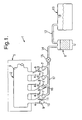
- a canister purge system 1 for a throttleless internal combustion engine system 2 includes a plurality of purge ports 3. Each of the purge ports 3 is adapted for connection to an intake port 4 of an internal combustion engine 5. An evaporative emissions canister 6 is in fluid communication with each purge port 3. Each purge port 3 includes a valve 7 that is responsive to pressure changes in the intake port 4, and permits vapor 8 to flow from the evaporative emissions canister 6 into the intake port 4 when a vacuum condition is present in the intake port 4. Valves 7 prevent flow from the intake port 4 to the evaporative emissions canister 6 when a vacuum is not present in the intake port 4.
- the throttleless internal combustion engine 5 illustrated schematically in Fig. 1 may be an engine of any one of various known engines that lack a throttle valve that would otherwise provide a vacuum in an intake manifold 9. Because throttleless internal combustion engines are known in the art, engine 5 will not be further described in detail herein.
- intake manifold 9 includes a plurality of intake ports 4, each of which is connected to a combustion chamber 10 having one or more intake valves 11, each of which is also illustrated schematically in Fig. 1.
- Each of the purge ports 3 are preferably connected to the intake ports immediately adjacent the intake valves 11. In the illustrated example, the purge port is located about 5.0-8.0 cm (about 2.5 inches) from the valve seat. However, the precise location of purge ports 3 will depend upon the configuration of the intake ports 4, combustion chamber 10, valves 11, and related components.
- a vapor pipe or tube 12 connects a vehicle gas tank 13 to the evaporative emissions canister 6 to convey vapors 18 from the tank.
- the vapors are absorbed by the active ingredient, such as activated charcoal, in the evaporative emissions container 6.
- a purge pipe or tube 14 is also connected to the evaporative emissions container 6, and leads to each of the purge ports 3.
- a flow control valve 15 is located in the purge tube 14 between the evaporative emissions canister 6 and the purge ports 3. Flow control valve 15 may be adjusted to control the total volume of flow from the canister 6 to the purge ports 3.
- valves 7 are preferably reed valves of a known construction having flexible flaps 16 made of a durable polymer material that resists degradation when exposed to the vapors.
- Valves 7 are somewhat similar in construction to reed valves utilized in conventional canister purge systems, except that the flexibility of flaps 16 and overall size of valve 7 is chosen to provide to desired one way flow upon vacuum under the operating conditions present in throttleless intake systems.
- the valves 7 are preferably positioned as close to the intake valve as possible, and permit vapor flow towards the intake port 4 when a vacuum is present in port 4, but prevent backflow from the intake port 4 through the purge ports 3.
- Fig. 2 is a cross-sectional view of a first embodiment of the canister purge system showing the location of the valves 7.
- Internal combustion engine 5 includes a cylinder head 20 having a fuel injection nozzle 22, and a spark plug 21. Gaskets 23 and 24 seal the intake manifold 9, and exhaust manifold 25, respectively, at the interface with the cylinder head 20. Valves 11 seal against valve seats 26 to selectively control flow into and out of combustion chamber 10.
- the center line 27 of purge port 3 intersects the intake port 4 at a distance "A" of about 5-6 cm from the valve seat 26. Also, in the illustrated example, the center line 27 of purge port 3 intersects center line 28 of intake port 4 at an angle "B" of about 60°.
- angle "B" could be substantially smaller for some applications, such as, for example, 45°, or 30°.
- the tubular housings 29 of valves 7 are press-fit, threaded, or otherwise fixed in opening 31 of intake manifold 9. Placement of the purge port 3 directly adjacent the intake valve 11 ensures that sufficient vacuum is generated to operate the valve 7.
- FIG. 3 Another embodiment of the canister purge system is illustrated in Fig. 3.
- the system of Fig. 3 is substantially similar to that of Fig. 2, except that valve 7 includes an elongated tubular portion 32 that extends through the opening 31 in intake manifold 9. Edge 34 of tip 33 of tube 32 extends at a non-orthogonal angle relative to the center line 27 of purge port 3, such that opening 35 of tube 32 is generally positioned downstream of the endmost sidewall 36 of tube 32.
- Purge port 3 illustrated in Fig. 3 is preferably located at a distance "A" of about 5-6 cm from the valve seat 26.
- the center line 27 of purge port 3 forms an angle "B" relative to the center line 28 of intake port 4 of about 60°, although this angle could vary as discussed above with respect to the embodiment illustrated in Fig. 2.
- the intermittent sub-atmospheric pressure fluctuations present in the intake ports 4 induce flow 8 through the purge ports 3 and reed valves 7.
- the intermittent fluctuations above atmospheric pressure cause the reed valves 7 to close, such that no flow is permitted out into the purge manifold 17.
- the pressure in purge manifold 17 drops to a relatively constant level slightly below atmospheric pressure, and this lower pressure condition purges the canister 6 in a manner that is substantially similar to a conventional system, even though the average pressure in the intake manifold 9 is nominally atmospheric.
- the flow control valve 15 permits the flow of purge vapor to be reduced below the maximum value, or even stopped if operating conditions so require.
- Flow control valve 15 may be operatively connected to an electronic engine control unit ("ECU") to provide automatic adjustment during operation based upon operating conditions.
- ECU electronic engine control unit
- the canister purge system of the present invention permits purging of an evaporative emissions canister in throttleless internal combustion engines, without requiring a vacuum pump or blower or other restriction in the intake tract that would otherwise be required to generate a vacuum condition.
- a "strangler" or other restriction could be placed in the intake manifold 9 to generate vacuum, such a restriction would likely at partially nullify the fuel economy benefits of an unthrottled engine.
- the canister purge system 1 is illustrated in connection with a four cylinder engine, the system could be utilized with an internal combustion engine having any number of cylinders by providing the proper number of valves 7 and purge ports 3, and operatively connecting the purge ports 3 to the canister 6.
- the canister purge system 1 of the present invention is inexpensive, and does not require pumps or other such devices that would otherwise drain power from the engine.
Landscapes
- Engineering & Computer Science (AREA)
- Chemical & Material Sciences (AREA)
- Combustion & Propulsion (AREA)
- Mechanical Engineering (AREA)
- General Engineering & Computer Science (AREA)
- Supplying Secondary Fuel Or The Like To Fuel, Air Or Fuel-Air Mixtures (AREA)
Applications Claiming Priority (2)
| Application Number | Priority Date | Filing Date | Title |
|---|---|---|---|
| US09/754,620 US6460517B1 (en) | 2001-01-04 | 2001-01-04 | Canister purge system |
| US754620 | 2001-01-04 |
Publications (2)
| Publication Number | Publication Date |
|---|---|
| EP1221547A2 true EP1221547A2 (de) | 2002-07-10 |
| EP1221547A3 EP1221547A3 (de) | 2003-12-03 |
Family
ID=25035598
Family Applications (1)
| Application Number | Title | Priority Date | Filing Date |
|---|---|---|---|
| EP01204860A Withdrawn EP1221547A3 (de) | 2001-01-04 | 2001-12-12 | Tankentlüftungssystem |
Country Status (2)
| Country | Link |
|---|---|
| US (1) | US6460517B1 (de) |
| EP (1) | EP1221547A3 (de) |
Cited By (4)
| Publication number | Priority date | Publication date | Assignee | Title |
|---|---|---|---|---|
| EP1798388A2 (de) * | 2005-12-14 | 2007-06-20 | Hengst GmbH & Co. KG | Einrichtungen zur Entlüftung des Kurbelgehäuses einer Brennkraftmaschine |
| WO2017102153A1 (de) * | 2015-12-14 | 2017-06-22 | Robert Bosch Gmbh | Tankentlüftungssystem, antrieb und fahrzeug |
| US9863373B2 (en) | 2014-01-30 | 2018-01-09 | Continental Automotive Systems, Inc. | Passive bypass valve for an active purge pump system module |
| WO2018192755A1 (de) * | 2017-04-20 | 2018-10-25 | Robert Bosch Gmbh | Tankentlüftungsvorrichtung |
Families Citing this family (18)
| Publication number | Priority date | Publication date | Assignee | Title |
|---|---|---|---|---|
| US6814771B2 (en) * | 2001-11-30 | 2004-11-09 | Delphi Technologies, Inc. | Evaporative emissions control device with internal seals |
| US6786468B2 (en) * | 2002-10-07 | 2004-09-07 | Delphi Technologies, Inc. | Unibody valve and techniques for making same for a purge control device |
| US20050044935A1 (en) * | 2003-08-26 | 2005-03-03 | Barrera Leonel A. | Integrated pressure sensor and carbon canister purge valve for vehicle engine |
| US20080308075A1 (en) * | 2007-06-13 | 2008-12-18 | Allen Christopher D | Automotive fuel system for substantially reducing hydrocarbon emissions into the atmosphere, and method |
| US20080308074A1 (en) * | 2007-06-13 | 2008-12-18 | Allen Christopher D | Evaporative emissions canister with external membrane |
| US20080308072A1 (en) * | 2007-06-13 | 2008-12-18 | Raja Banerjee | Hydrocarbon separation from air using membrane separators in recirculation tube |
| US20080308073A1 (en) * | 2007-06-13 | 2008-12-18 | Allen Christopher D | Evaporative emissions canister having an integral membrane |
| JP5078700B2 (ja) * | 2008-03-28 | 2012-11-21 | 本田技研工業株式会社 | 多気筒エンジンの吸気装置 |
| US8899158B2 (en) | 2012-07-31 | 2014-12-02 | Electro-Motive Diesel, Inc. | Consist having self-powered tender car |
| US9073556B2 (en) | 2012-07-31 | 2015-07-07 | Electro-Motive Diesel, Inc. | Fuel distribution system for multi-locomotive consist |
| US8925465B2 (en) | 2012-07-31 | 2015-01-06 | Electro-Motive Diesel, Inc. | Consist having self-propelled tender car |
| US8960100B2 (en) | 2012-07-31 | 2015-02-24 | Electro-Motive Diesel, Inc. | Energy recovery system for a mobile machine |
| US8919259B2 (en) | 2012-07-31 | 2014-12-30 | Electro-Motive Diesel, Inc. | Fuel system for consist having daughter locomotive |
| US8955444B2 (en) | 2012-07-31 | 2015-02-17 | Electro-Motive Diesel, Inc. | Energy recovery system for a mobile machine |
| US9193362B2 (en) | 2012-07-31 | 2015-11-24 | Electro-Motive Diesel, Inc. | Consist power system having auxiliary load management |
| US20150114370A1 (en) * | 2013-10-24 | 2015-04-30 | Ford Global Technologies, Llc | Fuel separation via fuel vapor management systems |
| US10767600B2 (en) | 2016-12-22 | 2020-09-08 | Polaris Industries Inc. | Evaporative emissions control for a vehicle |
| US11512670B2 (en) | 2019-07-03 | 2022-11-29 | Polaris Industries Inc. | Evaporative emissions control for a vehicle |
Citations (8)
| Publication number | Priority date | Publication date | Assignee | Title |
|---|---|---|---|---|
| JPS5121014A (en) * | 1974-08-14 | 1976-02-19 | Yamaha Motor Co Ltd | Takitonainenkikanno kyukisochi |
| JPS56118544A (en) * | 1980-02-26 | 1981-09-17 | Suzuki Motor Co Ltd | Purging device for vapored fuel recovery equipment |
| JPS58107866A (ja) * | 1982-11-13 | 1983-06-27 | Fuji Heavy Ind Ltd | 内燃機関の燃料蒸気処理装置 |
| US5655505A (en) * | 1994-04-22 | 1997-08-12 | Electro-Mechanical R & D Corp. | Apparatus and method for improving fuel efficiency of gasoline engines |
| US5803053A (en) * | 1996-03-23 | 1998-09-08 | Robert Bosch Gmbh | Method and arrangement for supplying fuel vapor to an internal combustion engine |
| EP0972931A2 (de) * | 1998-07-15 | 2000-01-19 | Toyota Jidosha Kabushiki Kaisha | Verfahren und Vorrichtung zum Behandeln von Brennstoffdampf für einen Magermotor |
| DE19922302A1 (de) * | 1999-05-14 | 2000-11-16 | Fev Motorentech Gmbh | Kolbenbrennkraftmaschine mit Mitteln zur Unterdruckerzeugung, insbesondere zum Entlüften des Kraftstofftanks |
| JP2001263178A (ja) * | 2000-03-22 | 2001-09-26 | Nippon Soken Inc | 筒内直接噴射式内燃機関のキャニスタパージ装置 |
Family Cites Families (10)
| Publication number | Priority date | Publication date | Assignee | Title |
|---|---|---|---|---|
| US4308842A (en) * | 1978-10-02 | 1982-01-05 | Honda Giken Kogyo Kabushiki Kaisha | Evaporative emission control system for an internal combustion engine |
| US4203401A (en) | 1979-01-29 | 1980-05-20 | General Motors Corporation | Evaporative emissions canister |
| JPS61257322A (ja) * | 1985-05-07 | 1986-11-14 | Nissan Motor Co Ltd | 燃料タンク用蒸発損失防止装置 |
| JPH0741882Y2 (ja) * | 1989-04-26 | 1995-09-27 | トヨタ自動車株式会社 | 蒸発燃料処理装置 |
| JP2666557B2 (ja) * | 1990-10-15 | 1997-10-22 | トヨタ自動車株式会社 | エバポパージシステムの故障診断装置 |
| US5190015A (en) * | 1991-02-05 | 1993-03-02 | Toyota Jidosha Kabushiki Kaisha | Evaporated fuel discharge suppressing apparatus for an internal combustion engine |
| US5103877A (en) | 1991-04-15 | 1992-04-14 | General Motors Corporation | Vapor-liquid separator for evaporative emissions control system |
| JP2970280B2 (ja) * | 1993-02-05 | 1999-11-02 | トヨタ自動車株式会社 | 発電機駆動用エンジンの制御装置 |
| US5762692A (en) | 1996-10-04 | 1998-06-09 | Ford Motor Company | Evaporative emissions control system for automotive vehicle |
| US6136075A (en) | 1999-05-03 | 2000-10-24 | Westvaco Corporation | Automotive evaporative emissions canister adsorptive restraint system |
-
2001
- 2001-01-04 US US09/754,620 patent/US6460517B1/en not_active Expired - Fee Related
- 2001-12-12 EP EP01204860A patent/EP1221547A3/de not_active Withdrawn
Patent Citations (8)
| Publication number | Priority date | Publication date | Assignee | Title |
|---|---|---|---|---|
| JPS5121014A (en) * | 1974-08-14 | 1976-02-19 | Yamaha Motor Co Ltd | Takitonainenkikanno kyukisochi |
| JPS56118544A (en) * | 1980-02-26 | 1981-09-17 | Suzuki Motor Co Ltd | Purging device for vapored fuel recovery equipment |
| JPS58107866A (ja) * | 1982-11-13 | 1983-06-27 | Fuji Heavy Ind Ltd | 内燃機関の燃料蒸気処理装置 |
| US5655505A (en) * | 1994-04-22 | 1997-08-12 | Electro-Mechanical R & D Corp. | Apparatus and method for improving fuel efficiency of gasoline engines |
| US5803053A (en) * | 1996-03-23 | 1998-09-08 | Robert Bosch Gmbh | Method and arrangement for supplying fuel vapor to an internal combustion engine |
| EP0972931A2 (de) * | 1998-07-15 | 2000-01-19 | Toyota Jidosha Kabushiki Kaisha | Verfahren und Vorrichtung zum Behandeln von Brennstoffdampf für einen Magermotor |
| DE19922302A1 (de) * | 1999-05-14 | 2000-11-16 | Fev Motorentech Gmbh | Kolbenbrennkraftmaschine mit Mitteln zur Unterdruckerzeugung, insbesondere zum Entlüften des Kraftstofftanks |
| JP2001263178A (ja) * | 2000-03-22 | 2001-09-26 | Nippon Soken Inc | 筒内直接噴射式内燃機関のキャニスタパージ装置 |
Non-Patent Citations (3)
| Title |
|---|
| PATENT ABSTRACTS OF JAPAN vol. 005, no. 199 (M-102), 17 December 1981 (1981-12-17) -& JP 56 118544 A (SUZUKI MOTOR CO LTD), 17 September 1981 (1981-09-17) * |
| PATENT ABSTRACTS OF JAPAN vol. 007, no. 211 (M-243), 17 September 1983 (1983-09-17) -& JP 58 107866 A (FUJI HEAVY IND LTD), 27 June 1983 (1983-06-27) * |
| PATENT ABSTRACTS OF JAPAN vol. 2000, no. 26, 1 July 2002 (2002-07-01) -& JP 2001 263178 A (NIPPON SOKEN INC), 26 September 2001 (2001-09-26) * |
Cited By (5)
| Publication number | Priority date | Publication date | Assignee | Title |
|---|---|---|---|---|
| EP1798388A2 (de) * | 2005-12-14 | 2007-06-20 | Hengst GmbH & Co. KG | Einrichtungen zur Entlüftung des Kurbelgehäuses einer Brennkraftmaschine |
| EP1798388A3 (de) * | 2005-12-14 | 2009-08-05 | Hengst GmbH & Co. KG | Einrichtungen zur Entlüftung des Kurbelgehäuses einer Brennkraftmaschine |
| US9863373B2 (en) | 2014-01-30 | 2018-01-09 | Continental Automotive Systems, Inc. | Passive bypass valve for an active purge pump system module |
| WO2017102153A1 (de) * | 2015-12-14 | 2017-06-22 | Robert Bosch Gmbh | Tankentlüftungssystem, antrieb und fahrzeug |
| WO2018192755A1 (de) * | 2017-04-20 | 2018-10-25 | Robert Bosch Gmbh | Tankentlüftungsvorrichtung |
Also Published As
| Publication number | Publication date |
|---|---|
| EP1221547A3 (de) | 2003-12-03 |
| US6460517B1 (en) | 2002-10-08 |
| US20020083931A1 (en) | 2002-07-04 |
Similar Documents
| Publication | Publication Date | Title |
|---|---|---|
| US6460517B1 (en) | Canister purge system | |
| US9651003B2 (en) | System and method for improving canister purging | |
| US9611816B2 (en) | System and method for improving canister purging | |
| US6880534B2 (en) | Evaporative fuel processing system | |
| US7007658B1 (en) | Vacuum shutdown system | |
| CN103362696B (zh) | 用于增压发动机的燃料蒸气抽送的模块化设计 | |
| US5967120A (en) | Returnless fuel delivery system | |
| US6805106B2 (en) | Fuel-injection system | |
| US5870997A (en) | Evaporative fuel controller for internal combustion engine | |
| US5427076A (en) | Evaporative fuel-processing system for internal combustion engines for vehicles | |
| US5335638A (en) | Evaporated fuel controller | |
| EP1054151A3 (de) | Eine Diagnostikvorrichtung für ein Verdampfungsemissionssteuersystem | |
| US4112898A (en) | Internal combustion engine with charcoal canister | |
| US6679228B1 (en) | Low evaporative emissions integrated air fuel module | |
| JP2020112121A (ja) | 蒸発燃料処理装置 | |
| EP1252430B1 (de) | Integriertes luft-brennstoff-modul mit niedrigen brennstoff-gas-emissionen | |
| JP4393810B2 (ja) | 蒸発燃料処理装置 | |
| JPH0299755A (ja) | 燃料タンクの内圧制御装置 | |
| US11585299B2 (en) | System and methods for a fuel tank pressure control pump | |
| JP3074840B2 (ja) | 蒸発燃料処理装置 | |
| CN116917155B (zh) | 用于燃料箱压力控制泵的系统和方法 | |
| JP7482505B2 (ja) | エンジンのガス燃料供給装置 | |
| JPH06108943A (ja) | 燃料噴射装置 | |
| KR0169896B1 (ko) | 액체연료 리턴구조를 갖는 증발가스 제어 시스템 | |
| KR100205996B1 (ko) | 자동차용 연료 공급 장치 |
Legal Events
| Date | Code | Title | Description |
|---|---|---|---|
| PUAI | Public reference made under article 153(3) epc to a published international application that has entered the european phase |
Free format text: ORIGINAL CODE: 0009012 |
|
| AK | Designated contracting states |
Kind code of ref document: A2 Designated state(s): AT BE CH CY DE DK ES FI FR GB GR IE IT LI LU MC NL PT SE TR |
|
| AX | Request for extension of the european patent |
Free format text: AL;LT;LV;MK;RO;SI |
|
| PUAL | Search report despatched |
Free format text: ORIGINAL CODE: 0009013 |
|
| AK | Designated contracting states |
Kind code of ref document: A3 Designated state(s): AT BE CH CY DE DK ES FI FR GB GR IE IT LI LU MC NL PT SE TR |
|
| AX | Request for extension of the european patent |
Extension state: AL LT LV MK RO SI |
|
| AKX | Designation fees paid | ||
| REG | Reference to a national code |
Ref country code: DE Ref legal event code: 8566 |
|
| STAA | Information on the status of an ep patent application or granted ep patent |
Free format text: STATUS: THE APPLICATION IS DEEMED TO BE WITHDRAWN |
|
| 18D | Application deemed to be withdrawn |
Effective date: 20040701 |