US11512670B2 - Evaporative emissions control for a vehicle - Google Patents
Evaporative emissions control for a vehicle Download PDFInfo
- Publication number
- US11512670B2 US11512670B2 US16/502,573 US201916502573A US11512670B2 US 11512670 B2 US11512670 B2 US 11512670B2 US 201916502573 A US201916502573 A US 201916502573A US 11512670 B2 US11512670 B2 US 11512670B2
- Authority
- US
- United States
- Prior art keywords
- fuel
- storage container
- evaporation canister
- frame
- vehicle
- Prior art date
- Legal status (The legal status is an assumption and is not a legal conclusion. Google has not performed a legal analysis and makes no representation as to the accuracy of the status listed.)
- Active, expires
Links
Images


Classifications
-
- F—MECHANICAL ENGINEERING; LIGHTING; HEATING; WEAPONS; BLASTING
- F02—COMBUSTION ENGINES; HOT-GAS OR COMBUSTION-PRODUCT ENGINE PLANTS
- F02M—SUPPLYING COMBUSTION ENGINES IN GENERAL WITH COMBUSTIBLE MIXTURES OR CONSTITUENTS THEREOF
- F02M25/00—Engine-pertinent apparatus for adding non-fuel substances or small quantities of secondary fuel to combustion-air, main fuel or fuel-air mixture
- F02M25/08—Engine-pertinent apparatus for adding non-fuel substances or small quantities of secondary fuel to combustion-air, main fuel or fuel-air mixture adding fuel vapours drawn from engine fuel reservoir
- F02M25/089—Layout of the fuel vapour installation
-
- B—PERFORMING OPERATIONS; TRANSPORTING
- B60—VEHICLES IN GENERAL
- B60K—ARRANGEMENT OR MOUNTING OF PROPULSION UNITS OR OF TRANSMISSIONS IN VEHICLES; ARRANGEMENT OR MOUNTING OF PLURAL DIVERSE PRIME-MOVERS IN VEHICLES; AUXILIARY DRIVES FOR VEHICLES; INSTRUMENTATION OR DASHBOARDS FOR VEHICLES; ARRANGEMENTS IN CONNECTION WITH COOLING, AIR INTAKE, GAS EXHAUST OR FUEL SUPPLY OF PROPULSION UNITS IN VEHICLES
- B60K15/00—Arrangement in connection with fuel supply of combustion engines or other fuel consuming energy converters, e.g. fuel cells; Mounting or construction of fuel tanks
- B60K15/03—Fuel tanks
- B60K15/035—Fuel tanks characterised by venting means
- B60K15/03504—Fuel tanks characterised by venting means adapted to avoid loss of fuel or fuel vapour, e.g. with vapour recovery systems
-
- B—PERFORMING OPERATIONS; TRANSPORTING
- B60—VEHICLES IN GENERAL
- B60K—ARRANGEMENT OR MOUNTING OF PROPULSION UNITS OR OF TRANSMISSIONS IN VEHICLES; ARRANGEMENT OR MOUNTING OF PLURAL DIVERSE PRIME-MOVERS IN VEHICLES; AUXILIARY DRIVES FOR VEHICLES; INSTRUMENTATION OR DASHBOARDS FOR VEHICLES; ARRANGEMENTS IN CONNECTION WITH COOLING, AIR INTAKE, GAS EXHAUST OR FUEL SUPPLY OF PROPULSION UNITS IN VEHICLES
- B60K15/00—Arrangement in connection with fuel supply of combustion engines or other fuel consuming energy converters, e.g. fuel cells; Mounting or construction of fuel tanks
- B60K15/03—Fuel tanks
- B60K15/063—Arrangement of tanks
-
- B—PERFORMING OPERATIONS; TRANSPORTING
- B60—VEHICLES IN GENERAL
- B60R—VEHICLES, VEHICLE FITTINGS, OR VEHICLE PARTS, NOT OTHERWISE PROVIDED FOR
- B60R9/00—Supplementary fittings on vehicle exterior for carrying loads, e.g. luggage, sports gear or the like
- B60R9/06—Supplementary fittings on vehicle exterior for carrying loads, e.g. luggage, sports gear or the like at vehicle front or rear
-
- B—PERFORMING OPERATIONS; TRANSPORTING
- B60—VEHICLES IN GENERAL
- B60K—ARRANGEMENT OR MOUNTING OF PROPULSION UNITS OR OF TRANSMISSIONS IN VEHICLES; ARRANGEMENT OR MOUNTING OF PLURAL DIVERSE PRIME-MOVERS IN VEHICLES; AUXILIARY DRIVES FOR VEHICLES; INSTRUMENTATION OR DASHBOARDS FOR VEHICLES; ARRANGEMENTS IN CONNECTION WITH COOLING, AIR INTAKE, GAS EXHAUST OR FUEL SUPPLY OF PROPULSION UNITS IN VEHICLES
- B60K15/00—Arrangement in connection with fuel supply of combustion engines or other fuel consuming energy converters, e.g. fuel cells; Mounting or construction of fuel tanks
- B60K15/03—Fuel tanks
- B60K2015/03072—Arrangements for reducing evaporation
-
- B—PERFORMING OPERATIONS; TRANSPORTING
- B60—VEHICLES IN GENERAL
- B60K—ARRANGEMENT OR MOUNTING OF PROPULSION UNITS OR OF TRANSMISSIONS IN VEHICLES; ARRANGEMENT OR MOUNTING OF PLURAL DIVERSE PRIME-MOVERS IN VEHICLES; AUXILIARY DRIVES FOR VEHICLES; INSTRUMENTATION OR DASHBOARDS FOR VEHICLES; ARRANGEMENTS IN CONNECTION WITH COOLING, AIR INTAKE, GAS EXHAUST OR FUEL SUPPLY OF PROPULSION UNITS IN VEHICLES
- B60K15/00—Arrangement in connection with fuel supply of combustion engines or other fuel consuming energy converters, e.g. fuel cells; Mounting or construction of fuel tanks
- B60K15/03—Fuel tanks
- B60K15/035—Fuel tanks characterised by venting means
- B60K15/03504—Fuel tanks characterised by venting means adapted to avoid loss of fuel or fuel vapour, e.g. with vapour recovery systems
- B60K2015/03514—Fuel tanks characterised by venting means adapted to avoid loss of fuel or fuel vapour, e.g. with vapour recovery systems with vapor recovery means
-
- B—PERFORMING OPERATIONS; TRANSPORTING
- B60—VEHICLES IN GENERAL
- B60K—ARRANGEMENT OR MOUNTING OF PROPULSION UNITS OR OF TRANSMISSIONS IN VEHICLES; ARRANGEMENT OR MOUNTING OF PLURAL DIVERSE PRIME-MOVERS IN VEHICLES; AUXILIARY DRIVES FOR VEHICLES; INSTRUMENTATION OR DASHBOARDS FOR VEHICLES; ARRANGEMENTS IN CONNECTION WITH COOLING, AIR INTAKE, GAS EXHAUST OR FUEL SUPPLY OF PROPULSION UNITS IN VEHICLES
- B60K15/00—Arrangement in connection with fuel supply of combustion engines or other fuel consuming energy converters, e.g. fuel cells; Mounting or construction of fuel tanks
- B60K15/03—Fuel tanks
- B60K15/035—Fuel tanks characterised by venting means
- B60K2015/03523—Arrangements of the venting tube
- B60K2015/03528—Mounting of venting tubes
-
- B—PERFORMING OPERATIONS; TRANSPORTING
- B60—VEHICLES IN GENERAL
- B60K—ARRANGEMENT OR MOUNTING OF PROPULSION UNITS OR OF TRANSMISSIONS IN VEHICLES; ARRANGEMENT OR MOUNTING OF PLURAL DIVERSE PRIME-MOVERS IN VEHICLES; AUXILIARY DRIVES FOR VEHICLES; INSTRUMENTATION OR DASHBOARDS FOR VEHICLES; ARRANGEMENTS IN CONNECTION WITH COOLING, AIR INTAKE, GAS EXHAUST OR FUEL SUPPLY OF PROPULSION UNITS IN VEHICLES
- B60K15/00—Arrangement in connection with fuel supply of combustion engines or other fuel consuming energy converters, e.g. fuel cells; Mounting or construction of fuel tanks
- B60K15/03—Fuel tanks
- B60K15/063—Arrangement of tanks
- B60K2015/0637—Arrangement of tanks the fuel tank is arranged in the front of the vehicle
-
- B—PERFORMING OPERATIONS; TRANSPORTING
- B60—VEHICLES IN GENERAL
- B60Y—INDEXING SCHEME RELATING TO ASPECTS CROSS-CUTTING VEHICLE TECHNOLOGY
- B60Y2200/00—Type of vehicle
- B60Y2200/10—Road Vehicles
- B60Y2200/12—Motorcycles, Trikes; Quads; Scooters
- B60Y2200/124—Buggies, Quads
Definitions
- the present disclosure generally relates to a fuel system of a vehicle, and more particularly, to a fuel system comprising components configured to reduce evaporative emissions.
- ATVs all-terrain vehicles
- UVs utility vehicles
- the packaging of the fuel system may be difficult in combination with other systems of the vehicle. More particularly, the inclusion of the components configured to reduce evaporative emissions may be difficult to package with the suspension system, cargo areas, powertrain, etc. As a result, there is a need for improved packaging of the vehicle components to provide space for an evaporative emissions system.
- an all-terrain vehicle comprises a frame, a plurality of ground engaging members supporting the frame, a straddle seat coupled to the frame for supporting at least one rider, a powertrain assembly operably coupled to the ground engaging members, the powertrain assembly comprising an engine, a storage container coupled to the frame at a position rearward of the straddle seat, an exterior surface of the storage container including an recess, and a fuel system fluidly coupled to the engine, the fuel system including a fuel tank, a fuel vapor line fluidly coupling the fuel tank to the engine, and an evaporation canister positioned along the fuel vapor line, wherein the evaporation canister is positioned within the recess in the exterior surface of the storage container.
- a vehicle in another embodiment, comprises a frame, a body supported by the frame, the body having a front body panel and a rear body panel, a plurality of ground engaging members supporting the frame, a seat coupled to the frame for supporting at least one rider, a powertrain assembly operably coupled to the ground engaging members, the powertrain assembly comprising an engine, an indented member positioned rearward of the seat, and a fuel system fluidly coupled to the engine, the fuel system including a fuel tank, a fuel vapor line fluidly coupling the fuel tank to the engine, and an evaporation canister positioned along the fuel vapor line, wherein at least a portion of the evaporation canister is positioned between an upper-facing surface of the indented member and a bottom surface of the rear body panel.
- FIG. 1 shows a left front perspective view of an embodiment of a vehicle of the present disclosure
- FIG. 2 shows a rear view of the vehicle of FIG. 1 ;
- FIG. 3 shows a left side view of the vehicle of FIG. 1 ;
- FIG. 4 shows a left side view of an engine, a fuel system, a portion of a frame, a seat, and a storage container of the vehicle of FIG. 1 ;
- FIG. 5 shows a top plan view of the fuel system, the seat, the engine, the portion of the frame, and the storage container of the vehicle in FIG. 4 ;
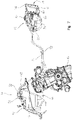
- FIG. 6 shows a left front perspective view of the fuel system, the engine, and the storage container of FIG. 4 ;
- FIG. 7 shows a left side view of the fuel system, the engine, and the storage container of FIG. 6 ;
- FIG. 8 shows a left front perspective view of a top portion of the storage container and an evaporation canister of the fuel system of FIG. 4 ;
- FIG. 9 shows a top plan view of the top portion of the storage container of FIG. 8 with the evaporation canister removed;
- FIG. 10 shows a front plan view of the top portion of the storage container of FIG. 8 with the evaporation canister removed;
- FIG. 11 shows a perspective cross sectional view of a rear portion of the vehicle of FIG. 1 taken along line 11 - 11 ;
- FIG. 12 shows a left front perspective view of the fuel system and the engine with a bracket for securing an evaporation canister of the fuel system to the vehicle;
- FIG. 13 shows a left side view of the fuel system, the engine, and the bracket of FIG. 12 ;
- FIG. 14 shows a left front perspective view of the bracket and the evaporation canister of the fuel system of FIG. 12 ;
- FIG. 15 shows a top plan view of the bracket of FIG. 12 with the evaporation canister removed.
- FIG. 16 shows a front plan view of the bracket of FIG. 12 with the evaporation canister removed.
- an all-terrain vehicle (“ATV”) 10 is configured to be supported on a ground surface with front ground-engaging members, illustratively front wheels 12 , and rear ground-engaging members, illustratively rear wheels 14 .
- Front and rear wheels 12 , 14 are operably coupled to a brake assembly (not shown).
- front and rear wheels 12 , 14 are operably coupled to a powertrain assembly that generally includes an engine 16 ( FIGS. 4, 6, and 7 ) which is operably coupled to an exhaust assembly 18 ( FIG. 2 ).
- front wheels 12 support a front end 20 of ATV 10 which includes at least a front rack 22 , a front body panel 24 , and a front suspension assembly 26 .
- Rear wheels 14 support a rear end 28 of ATV 10 , which includes at least a rear rack 30 , a rear body panel 32 , the exhaust assembly 18 , and a rear suspension assembly 34 .
- front and rear wheels 12 , 14 of ATV 10 further support a frame assembly 36 .
- frame assembly 36 includes a lower frame assembly 38 as well as an upper frame assembly 40 ( FIG. 4 ).
- Upper frame assembly 40 includes at least one longitudinal frame member 41 that supports a seat 42 for at least an operator.
- seat 42 is a straddle seat configured to support one or two riders.
- Seat 42 is supported by upper frame assembly 40 between front end 20 and rear end 28 .
- ATV 10 further includes a fuel system 44 fluidly coupled to engine 16 and generally supported by frame assembly 36 .
- Fuel system 44 generally includes a fuel tank 46 fluidly coupled to engine 16 by a fuel delivery line 48 .
- Fuel tank 46 includes a fill opening 50 , a vapor exit port 52 , and a fuel pump 54 , and is generally positioned forward of seat 42 ( FIGS. 4 and 5 ).
- Fill opening 50 of fuel tank 46 is configured to receive liquid fuel from a fuel delivery apparatus, and generally includes a cap 56 for containing both liquid fuel and fuel vapor within fuel tank 46 .
- fill opening 50 is generally accessible from a top side of fuel tank 46 of ATV 10 .
- Vapor exit port 52 of fuel tank 46 is configured to allow venting of fuel vapors collecting within fuel tank 46 , and prevent liquid fuel from escaping fuel tank 46 , specifically in the case where ATV 10 is not in an upright position. Accordingly, vapor exit port 52 prevents liquid fuel from entering a fuel vapor line 58 which is configured to receive fuel vapor from fuel tank 46 through vapor exit port 52 .
- fuel pump 54 of fuel tank 46 is configured to deliver liquid fuel from fuel tank 46 to engine 16 through fuel delivery line 48 based on the operating conditions of ATV 10 , for example based on information received from throttle controls of ATV 10 .
- fuel vapor may be present and, therefore, could travel to engine 16 and ultimately exhaust assembly 18 ; however, the emission of fuel vapor from ATV 10 may be regulated by emissions regulations. As such, it is necessary to contain the fuel vapor within fuel system 44 according to these emissions regulations. Therefore, fuel system 44 of ATV 10 further includes an evaporative emissions control assembly 60 ( FIG. 6 ) to control emission of the fuel vapor from ATV 10 .
- evaporative emissions control assembly 60 includes fuel vapor line 58 fluidly coupling fuel tank 46 to engine 16 , an evaporation or an active carbon canister 62 positioned along fuel vapor line 58 and configured to receive and/or store fuel vapor received from fuel tank 46 , a fresh air intake 64 ( FIG.
- evaporation canister 62 coupled to evaporation canister 62 and configured to provide fresh ambient air for mixing with the fuel vapor within evaporation canister 62 , an air filter assembly 66 fluidly coupled to fresh air intake 64 to filter the fresh ambient air, and a purge valve 68 positioned along fuel vapor line 58 and configured to control the amount of fuel vapor delivered to engine 16 from fuel tank 46 and/or evaporation canister 62 .
- fuel vapor line 58 includes a fuel vapor load line 70 extending between fuel tank 46 and evaporation canister 62 and a fuel vapor purge line 72 extending between evaporation canister 62 and engine 16 , where purge valve 68 is positioned along fuel vapor purge line 72 of fuel vapor line 58 in order to control the amount of fuel vapor delivered to engine 16 .
- the fresh air provided to canister 62 through fresh air intake 64 flows along a flow path through canister 62 to engine 16 pulling out the fuel vapor from canister 62 and providing the mixture to engine 16 .
- Evaporative emissions control assembly 60 is configured such that fuel vapor from fuel tank 46 , which is positioned forward of seat 42 , is vented through vapor exit port 52 and travels through fuel vapor load line 70 of fuel vapor line 58 to evaporation canister 62 , which is rearward of seat 42 .
- fuel system 44 extends between front end 20 and rear end 28 and is generally positioned above or along upper framer assembly 40 . This allows for the recovery of fuel vapor within fuel tank 46 such that the vapor may be sent back and used by engine 16 instead of allowing the fuel vapor to escape and evaporate into the air.
- Evaporation canister 62 adsorbs and stores the fuel vapors from tank 46 until purge valve 68 is opened allowing fuel vapors and air to travel through fuel vapor purge line 72 of fuel vapor line 58 and purge valve 68 and into engine 16 .
- Evaporation canister 62 is also coupled to fresh air intake 64 through air intake line 74 such that ambient air is pulled into evaporation canister 62 through air filter assembly 66 , which is positioned along air intake line 74 , to mix with the fuel vapors within evaporation canister 62 and create the flow path through the canister when purge valve 68 is opened.
- fuel vapor load line 70 may include a check valve or pressure-vent valve (not shown) that pressurizes fuel tank 46 and controls the amount and timing of fuel vapor transferring from fuel tank 46 to evaporation canister 62 .
- fuel vapor load line 70 is coupled to evaporation canister 62 at load port 71
- fuel vapor purge line 72 is coupled to evaporation canister 62 at purge port 73
- air intake line 74 is coupled to evaporation canister 62 at air intake port 75 such that load port 71 is positioned below purge port 73 on a first end or side 77 of evaporation canister 62 and air intake port 75 is on a second end or side 79 of evaporation canister 62 .
- load port 71 is positioned adjacent to the bottom edge of canister 62 and/or canister 62 may be tilted such that liquid fuel can be prevented from carrying up canister 62 .
- evaporation canister 62 is generally positioned in close proximity to exhaust assembly 18 with a heat shield 19 positioned between exhaust assembly 18 and evaporation canister 62 ( FIG. 11 ). Due to the proximity of exhaust assembly 18 , purging of evaporation canister 62 is improved due to the fact that the heat produced by exhaust assembly 18 helps keep the fuel vapor in vapor form rather than allowing the vapor to cool and condense into liquid form. If liquid fuel reaches evaporation canister 62 , some of the carbon within canister 62 can be permanently filled, thereby reducing the working capacity of canister 62 .
- evaporation canister 62 is positioned at a height substantially similar to that of vapor exit port 52 such that gravity does not affect the fuel vapor traveling from fuel tank 46 to evaporation canister 62 and helps keep the fuel vapor in vapor form rather than condensing to liquid form. If canister is much farther below fuel tank vent, gravity would pull any condensed fuel vapor into the canister which should be avoided as was noted. As such, both evaporation canister 62 and vapor exit port 52 are positioned within an upper half of ATV 10 above longitudinal frame member 41 , a bottommost extent of seat 42 , and an uppermost extent of the engine.
- the difference between the height of evaporation canister 62 and the height of vapor exit port 52 may be approximately 6 inches or less.
- the length of fuel vapor load line 70 which extends from fuel tank 46 past seat 42 to evaporation canister 62 , also allows for any condensed fuel within line 70 to eventually evaporate again before traveling to evaporation canister 62 , or at least requires condensed fuel to take longer to get to evaporation canister 62 such that the life of evaporation canister 62 may be extended.
- ATV 10 further includes a storage container 76 supported by a rear end of frame assembly 36 and positioned rearward of seat 42 and fuel tank 46 .
- Storage container 76 includes a top lid portion 78 and a bottom storage portion 80 , where top lid portion 78 and bottom storage portion 80 may be separate components configured to couple together or a single, unitary component.
- An upper-facing surface 84 of top lid portion 78 generally includes a recess 82 configured to receive evaporation canister 62 such that evaporation canister 62 is positioned between upper-facing surface 84 of storage container 76 and rear body panel 32 .
- At least a portion of evaporation canister 62 is positioned above an uppermost extent of storage container 76 .
- Upper surface 84 also includes a plurality of channels 86 configured to receive fuel vapor line 58 and/or air intake line 74 .
- Recess 82 is positioned in the middle of top portion 78 between a forward edge 88 , a rearward edge 90 , and two side edges 92 , 94 such that evaporation canister 62 is not visible from plain view. In other words, evaporation canister 62 is not visible when positioned within recess 82 of storage container 76 , and storage container 76 and rear body panel 32 are coupled to frame assembly 36 .
- recess 82 and/or channels 86 may include one or more retention member (i.e., ribs 96 or legs) ( FIG. 9 ) configured to retain evaporation canister 62 , fuel vapor line 58 and/or air intake line 74 .
- the plurality of channels in upper surface 84 include two channels 86 a configured to receive fuel vapor load line 70 of fuel vapor line 58 and three channels 86 b configured to receive air intake line 74 .
- storage container 76 further includes an access panel or door 31 coupled to top lid portion 78 and/or bottom storage portion 80 and facing the rear of ATV 10 such that storage container 76 is accessible from the rear of ATV 10 .
- Access panel 31 may be coupled via a living hinge, a conventional hinge, a removable coupler, or any other coupling mechanism. Accordingly, ATV 10 does not lose functional storage while allowing for the addition of evaporative emissions control assembly 60 and evaporation canister 62 .
- evaporation canister 62 in upper-facing surface 84 of top lid portion 78 of storage container 76 keeps evaporation canister 62 out of sight and generally inaccessible while also allowing evaporation canister 62 to be positioned in such a way that gravity does not affect the fuel vapor traveling from fuel tank 46 to evaporation canister 62 .
- air intake line 74 and/or fuel vapor line 58 may include a heat shield or be made of a material with sufficient heat resistant properties at least within an outer layer to protect air intake line 74 and/or fuel vapor line 58 from the heat produced by exhaust assembly 18 . Because air intake line 74 passes between storage container 76 and exhaust assembly 18 and fuel vapor line 58 extends near exhaust assembly 18 , the heat shield and/or heat resistant materials protect and maintain the components of evaporative emissions control assembly 60 .
- air intake line 74 and/or fuel vapor line 58 may be formed of a multilayer rubber where an interior layer is formed of a material having sufficient chemical resistant properties for coming in contact with fuel.
- top lid portion 78 of storage container 76 may further include a drain spout 98 .
- Drain spout 98 may be formed in upper surface 84 of top portion 78 , and is configured to allow water and/or debris that on top lid portion 78 or within recess 82 to drain out of top lid portion 78 .
- Drain spout 98 is a channel extending from recess 82 to a forwardmost extent of top portion 78 that includes an inlet 100 within or along a front edge 81 of recess 82 and an outlet 102 along front edge 88 of top lid portion 78 .
- drain spout 98 , inlet 100 and outlet 102 may be U-shaped, and fuel vapor line 58 and/or air intake line 74 may intersect and extend over and/or through drain spout 98 .
- drain spout 98 is also angled from inlet 100 within recess 82 to outlet 102 such that inlet 100 is positioned higher than outlet 102 .
- top lid portion 78 further includes a securing assembly 104 for securing evaporation canister 62 within recess 82 .
- securing assembly 104 includes a strap 106 and a hook 107 .
- Strap 106 includes a first end 108 configured to be held in place by a loop or securing member 110 coupled to upper surface 84 of top portion 76 , and a second end 112 configured to couple with hook 107 extending upward from upper surface 84 .
- Strap 106 may be formed of various materials, for example strap 106 may be made of a multilayer rubber having sufficient chemical and heat resistance properties to prevent strap 106 from melting or degrading due to the heat of exhaust assembly 18 .
- strap 106 extends between extension members 109 such that the width of strap 106 is the same width as the space between extension members 109 . Having strap 106 be the same width as the space between extension member 109 allows for a reduction in vibration and side-to-side motion of canister 62 .
- a bracket 200 may be formed with a shape or recess 82 ′ similar to recess 82 that includes tabs or extensions 202 for coupling bracket 200 to a lower surface 33 ( FIG. 11 ) of rear body panel 32 .
- bracket 200 includes a single extension on both sides of bracket 200 configured to couple bracket 200 to rear body panel 32
- bracket 200 includes a plurality of tabs 202 on both sides of bracket 200 configured to couple bracket 200 to rear body panel 32
- bracket 200 includes a single extension 202 a on one side and multiple extensions 202 b on the other side of bracket 200 configured to couple bracket 200 to rear body panel 32 .
- rear body panel 32 may include one or more downward extensions or dog house mount features for coupling extensions 202 of bracket 200 to rear body panel 32 .
- Bracket 200 allows canister 62 to be coupled between an upper surface of bracket 200 and lower surface 33 of rear body panel 32 .
- bracket 200 generally includes a body 203 and a coupling mechanism 204 for securing canister 62 within body 203 of bracket 200 .
- Body 203 generally includes extensions 202 and an opening 206 in the bottom of body 203 configured to fit extensions 109 of canister 62 .
- opening 206 includes a first end 208 and a second end 210 , where first end 208 is wider than second end 210 similar to the spacing of extensions 109 such that extensions 109 of canister 62 fit snuggly through opening 206 , and canister 62 cannot be installed incorrectly. Opening 206 is also configured to allow debris or fluid to escape bracket 200 to avoid debris/fluid build up within bracket 200 .
- body 203 may also include ribs/indentions 212 to match or fit with ribs/indentions in canister 62 .
- coupling mechanism 204 of bracket 200 may be a living hinge including a hinge end 214 and free end 216 , where free end 216 includes an opening 218 for receiving a coupler (i.e., self-tapper, snap input or clip, etc.) (not shown) for coupling free end 216 of living hinge 204 to opening 220 of body 203 of bracket 200 .
- Opening 220 of bracket 200 generally includes additional material to allow free end 216 of living hinge 204 to be coupled to body 203 with the coupler.
Abstract
Description
Claims (23)
Priority Applications (2)
| Application Number | Priority Date | Filing Date | Title |
|---|---|---|---|
| US16/502,573 US11512670B2 (en) | 2019-07-03 | 2019-07-03 | Evaporative emissions control for a vehicle |
| US17/984,794 US20230072911A1 (en) | 2019-07-03 | 2022-11-10 | Evaporative emissions control for a vehicle |
Applications Claiming Priority (1)
| Application Number | Priority Date | Filing Date | Title |
|---|---|---|---|
| US16/502,573 US11512670B2 (en) | 2019-07-03 | 2019-07-03 | Evaporative emissions control for a vehicle |
Related Child Applications (1)
| Application Number | Title | Priority Date | Filing Date |
|---|---|---|---|
| US17/984,794 Division US20230072911A1 (en) | 2019-07-03 | 2022-11-10 | Evaporative emissions control for a vehicle |
Publications (2)
| Publication Number | Publication Date |
|---|---|
| US20210003101A1 US20210003101A1 (en) | 2021-01-07 |
| US11512670B2 true US11512670B2 (en) | 2022-11-29 |
Family
ID=74066015
Family Applications (2)
| Application Number | Title | Priority Date | Filing Date |
|---|---|---|---|
| US16/502,573 Active 2040-10-21 US11512670B2 (en) | 2019-07-03 | 2019-07-03 | Evaporative emissions control for a vehicle |
| US17/984,794 Pending US20230072911A1 (en) | 2019-07-03 | 2022-11-10 | Evaporative emissions control for a vehicle |
Family Applications After (1)
| Application Number | Title | Priority Date | Filing Date |
|---|---|---|---|
| US17/984,794 Pending US20230072911A1 (en) | 2019-07-03 | 2022-11-10 | Evaporative emissions control for a vehicle |
Country Status (1)
| Country | Link |
|---|---|
| US (2) | US11512670B2 (en) |
Families Citing this family (4)
| Publication number | Priority date | Publication date | Assignee | Title |
|---|---|---|---|---|
| JP2022184238A (en) * | 2021-05-31 | 2022-12-13 | ヤマハ発動機株式会社 | Saddle-riding type vehicle |
| JP2022184239A (en) | 2021-05-31 | 2022-12-13 | ヤマハ発動機株式会社 | Saddle-riding type vehicle |
| JP2022184240A (en) | 2021-05-31 | 2022-12-13 | ヤマハ発動機株式会社 | Saddle riding type vehicle |
| JP2022184241A (en) * | 2021-05-31 | 2022-12-13 | ヤマハ発動機株式会社 | Saddle-riding type vehicle |
Citations (142)
| Publication number | Priority date | Publication date | Assignee | Title |
|---|---|---|---|---|
| US4381753A (en) | 1979-11-12 | 1983-05-03 | Honda Giken Kogyo Kabushiki Kaisha | Evaporative emission control device of an internal combustion engine for vehicle use |
| US4727955A (en) | 1985-12-28 | 1988-03-01 | Nissan Motor Company, Ltd. | Carbon canister drained vapor diffusing device |
| US4853009A (en) | 1988-08-31 | 1989-08-01 | General Motors Corporation | Multi orientation fuel vapor storage canister assembly |
| US4951637A (en) | 1989-06-29 | 1990-08-28 | Siemens-Bendix Automotive Electronics Limited | Purge flow regulator |
| US5058693A (en) | 1990-05-07 | 1991-10-22 | Industrial Strainer Co. | Remote filter assembly for vapor recovery system |
| US5477836A (en) | 1994-02-02 | 1995-12-26 | Toyota Jidosha Kabushiki Kaisha | Fuel vapor emission control system for an engine |
| US5647333A (en) | 1995-02-22 | 1997-07-15 | Suzuki Motor Corporation | Evaporative fuel control system for an internal combustion engine |
| US5702125A (en) | 1994-08-17 | 1997-12-30 | Honda Giken Kogyo Kabushiki Kaisha | Arrangement of disposition of canister in vehicle |
| US5806500A (en) | 1997-02-03 | 1998-09-15 | Ford Motor Company | Fuel vapor recovery system |
| US5817925A (en) | 1997-03-26 | 1998-10-06 | Siemens Electric Limited | Evaporative emission leak detection system |
| US5988145A (en) | 1997-03-04 | 1999-11-23 | Honda Giken Kogyo Kabushiki Kaisha | Drain pipe of canister |
| US6105708A (en) | 1997-08-08 | 2000-08-22 | Suzuki Motor Corporation | Piping device in atmospheric side of canister for vehicle |
| JP2000345929A (en) | 1999-06-01 | 2000-12-12 | Nissan Motor Co Ltd | Fuel tank device |
| US6308987B1 (en) | 1998-12-09 | 2001-10-30 | Suzuki Motor Corporation | Canister attachment construction of a vehicle |
| US20010047723A1 (en) | 2000-06-06 | 2001-12-06 | Honda Giken Kogyo Kabushiki Kaisha | Canister mounting structure |
| JP2001342921A (en) | 2000-05-31 | 2001-12-14 | Keihin Corp | Fuel feed device for internal combustion engine |
| JP2002013445A (en) | 2000-06-30 | 2002-01-18 | Honda Motor Co Ltd | Evaporation fuel treating device |
| US6363920B1 (en) | 2000-05-25 | 2002-04-02 | Eaton Corporation | Proportional solenoid for purging fuel vapors |
| JP2002266709A (en) | 2001-03-06 | 2002-09-18 | Honda Motor Co Ltd | Device for treating evaporated fuel |
| US6460517B1 (en) | 2001-01-04 | 2002-10-08 | Delphi Technologies, Inc. | Canister purge system |
| JP3336912B2 (en) | 1997-06-25 | 2002-10-21 | トヨタ自動車株式会社 | Evaporative fuel purge system for engine |
| JP3343569B2 (en) | 1993-06-01 | 2002-11-11 | スズキ株式会社 | Evaporation system for motorcycle |
| JP2003237390A (en) | 2002-02-13 | 2003-08-27 | Honda Motor Co Ltd | Arrangement structure for vehicular canister |
| US20040075269A1 (en) | 2002-10-22 | 2004-04-22 | Honda Giken Kogyo Kabushiki Kaisha | Canister mounting structure |
| TH61921A (en) | 2003-09-18 | 2004-05-04 | นายธเนศ เปเรร่า | Structure for installing a fuel trap box |
| US20040200356A1 (en) | 2003-04-09 | 2004-10-14 | Kuperus Peter P. | Fuel tank assembly |
| JP2004293296A (en) | 2003-02-07 | 2004-10-21 | Mitsubishi Electric Corp | Fuel vapor leak detecting device and fuel supplying device applied to the same |
| JP3666645B2 (en) | 2000-02-09 | 2005-06-29 | 日産自動車株式会社 | Fuel vapor recovery device |
| US20050211496A1 (en) | 2004-02-12 | 2005-09-29 | Mazda Motor Corporation | Fuel tank disposition structure of vehicle |
| US20050241480A1 (en) | 2004-04-28 | 2005-11-03 | Lebowitz Jeffrey L | Filter material absorb hydrocarbon |
| US20060043131A1 (en) * | 2004-08-31 | 2006-03-02 | Graham Steven L | Under-seat storage container |
| US7008470B2 (en) | 2000-12-25 | 2006-03-07 | Aisan Kogyo Kabushiki Kaisha | Canister |
| JP2006070785A (en) | 2004-09-01 | 2006-03-16 | Keihin Corp | Throttle body |
| US20060065253A1 (en) | 2004-09-29 | 2006-03-30 | Reddy Sam R | Method and system of purging evaporative emission control canister using heated purge air |
| JP2007146793A (en) | 2005-11-30 | 2007-06-14 | Mahle Filter Systems Japan Corp | Canister |
| US7237644B2 (en) | 2002-11-19 | 2007-07-03 | Honda Motor Co., Ltd. | Vehicle canister arranging structure |
| JP2007196967A (en) | 2006-01-30 | 2007-08-09 | Toyota Motor Corp | Hybrid vehicle and hybrid vehicle charger |
| US20070266997A1 (en) | 2005-09-23 | 2007-11-22 | Clontz Clarence R Jr | Evaporative emission control using selective heating in an adsorbent canister |
| US20080041226A1 (en) | 2005-09-23 | 2008-02-21 | Hiltzik Laurence H | Selective heating in adsorbent systems |
| US20080149075A1 (en) | 2006-12-21 | 2008-06-26 | Nissan Motor Co., Ltd. | Canister device |
| JP2008248795A (en) | 2007-03-30 | 2008-10-16 | Honda Motor Co Ltd | Vehicular canister attachment structure |
| US7438058B2 (en) | 2006-03-02 | 2008-10-21 | Honda Motor Co., Ltd. | Drain pipe in canister system |
| JP2009002267A (en) | 2007-06-22 | 2009-01-08 | Honda Motor Co Ltd | Mounting structure of canister for vehicle |
| US20090013973A1 (en) | 2007-07-12 | 2009-01-15 | Mahle Filter Systems Japan Corporation | Fuel vapor storage canister, fuel vapor adsorbent for canister, and method of producing fuel vapor adsorbent |
| EP2063098A1 (en) | 2005-11-18 | 2009-05-27 | Basf Catalysts Llc | Hydrocarbon adsorption method and device for controlling evaporative emissions from the fuel storage system of motor vehicles |
| EP2071172A1 (en) | 2007-12-13 | 2009-06-17 | Delphi Technologies, Inc. | Canister with overmolded filter |
| JP2009137583A (en) | 2009-01-27 | 2009-06-25 | Honda Motor Co Ltd | Mounting structure of canister |
| US20090195035A1 (en) * | 2008-02-04 | 2009-08-06 | Polaris Industries Inc. | ATV having arrangement for a passenger |
| WO2009098806A1 (en) | 2008-02-06 | 2009-08-13 | Aisan Kogyo Kabushiki Kaisha | Canister |
| JP2009215901A (en) | 2008-03-07 | 2009-09-24 | Honda Motor Co Ltd | Mounting structure for canister |
| JP4355312B2 (en) | 2005-12-13 | 2009-10-28 | 本田技研工業株式会社 | Arrangement structure of canister in vehicle |
| EP2143584A1 (en) | 2008-07-07 | 2010-01-13 | Honda Motor Co., Ltd. | Vehicular Canister Mounting Structure |
| WO2010003277A1 (en) | 2008-07-11 | 2010-01-14 | 金发科技股份有限公司 | A semi-aromatic polyamide and the process with low amount of waste water discharge for preparing the same |
| WO2010032065A1 (en) | 2008-09-22 | 2010-03-25 | Mast Carbon Automotive Ltd. | Fuel vapour storage |
| US20100078241A1 (en) | 2008-09-29 | 2010-04-01 | Honda Motor Co., Ltd. | Canister mounting structure for motorcycle and motorcycle |
| JP2010155506A (en) | 2008-12-26 | 2010-07-15 | Honda Motor Co Ltd | Saddle-riding type vehicle |
| US20100243358A1 (en) * | 2009-03-31 | 2010-09-30 | Honda Motor Co., Ltd. | Canister mounting structure for a saddle-type vehicle, and vehicle incorporating same |
| US20100243355A1 (en) | 2009-03-30 | 2010-09-30 | Honda Motor Co., Ltd. | Arrangement structure for canister of saddle type vehicle |
| US7841624B2 (en) | 2007-04-26 | 2010-11-30 | Honda Motor Co., Ltd. | Vehicle body structure having fuel tank and canister |
| EP2264305A1 (en) | 2008-03-07 | 2010-12-22 | Honda Motor Co., Ltd. | Canister mounting structure |
| US20110073399A1 (en) | 2009-09-30 | 2011-03-31 | Honda Motor Co., Ltd. | Arrangement structure for evaporated fuel treatment device of saddle-type vehicle, and vehicle incorporating same |
| US20110297127A1 (en) | 2009-02-16 | 2011-12-08 | Toyota Jidosha Kabushiki Kaisha | Device for treating evaporated fuel |
| US8113312B2 (en) | 2009-07-31 | 2012-02-14 | Honda Motor Co., Ltd. | Evaporative emissions canister arrangement for a motorcycle, and motorcycle incorporating same |
| US8118128B2 (en) | 2008-09-16 | 2012-02-21 | Honda Motor Co., Ltd. | Canister-holding structure for supporting a cylindrical canister in a vehicle |
| US8141672B2 (en) | 2008-08-29 | 2012-03-27 | Honda Motor Co., Ltd. | Canister layout structure in motorcycle |
| JP2012132402A (en) | 2010-12-24 | 2012-07-12 | Mahle Filter Systems Japan Corp | Canister |
| US8251048B2 (en) | 2009-03-03 | 2012-08-28 | Honda Motor Co., Ltd. | Evaporated fuel controlling apparatus for all terrain vehicle |
| US8276944B2 (en) | 2009-03-26 | 2012-10-02 | Honda Motor Co., Ltd. | Evaporated fuel treatment apparatus in motorcycle |
| US8276702B2 (en) | 2009-03-26 | 2012-10-02 | Honda Motor Co., Ltd. | Motorcycle |
| US8342282B2 (en) * | 2008-06-20 | 2013-01-01 | Honda Motor Co., Ltd. | Motorcycle |
| US8342358B2 (en) | 2007-02-13 | 2013-01-01 | Honda Motor Co., Ltd. | Fuel tank device |
| JP5154506B2 (en) | 2009-05-18 | 2013-02-27 | 愛三工業株式会社 | Evaporative fuel processing equipment |
| US8418794B2 (en) | 2008-03-07 | 2013-04-16 | Yamaha Hatsudoki Kabushiki Kaisha | Straddle-type vehicle |
| JP2013067270A (en) | 2011-09-22 | 2013-04-18 | Honda Motor Co Ltd | Canister arrangement structure of straddle-type vehicle |
| JP2013067272A (en) | 2011-09-22 | 2013-04-18 | Honda Motor Co Ltd | Canister arrangement structure of straddle-type vehicle |
| JP2013067277A (en) | 2011-09-22 | 2013-04-18 | Honda Motor Co Ltd | Canister arrangement structure of straddle-type vehicle |
| JP2013067296A (en) | 2011-09-22 | 2013-04-18 | Honda Motor Co Ltd | Canister arrangement structure of straddle-type vehicle |
| EP2607677A1 (en) * | 2011-12-20 | 2013-06-26 | Suzuki Motor Corporation | Canister arrangement structure of motorcycle |
| WO2013094549A1 (en) | 2011-12-21 | 2013-06-27 | 本田技研工業株式会社 | Straddled vehicle |
| WO2013094631A1 (en) | 2011-12-21 | 2013-06-27 | 本田技研工業株式会社 | Straddled vehicle |
| US8490733B2 (en) | 2010-02-09 | 2013-07-23 | Suzuki Motor Corporation | Motorcycle |
| JP2013189200A (en) | 2013-05-13 | 2013-09-26 | Honda Motor Co Ltd | Motorcycle |
| US20130247881A1 (en) | 2012-03-22 | 2013-09-26 | Honda Motor Co., Ltd. | Canister arrangement structure for saddle-ride type vehicle |
| US8560167B2 (en) | 2011-02-18 | 2013-10-15 | Ford Global Technologies, Llc | System and method for performing evaporative leak diagnostics in a vehicle |
| US8573183B2 (en) | 2010-07-14 | 2013-11-05 | Honda Motor Co., Ltd. | System and method for fuel tank tube routing and valve placement to prevent fuel leaks into evaporative emissions system |
| US8646668B2 (en) * | 2009-08-07 | 2014-02-11 | Honda Motor Company, Ltd. | Storage container for a vehicle |
| US20140060955A1 (en) | 2012-09-05 | 2014-03-06 | Honda Motor Co., Ltd. | Canister arrangement structure of straddle type vehicle |
| JP5481254B2 (en) | 2010-03-31 | 2014-04-23 | 本田技研工業株式会社 | vehicle |
| US8726888B2 (en) | 2009-03-30 | 2014-05-20 | Honda Motor Co., Ltd | Atmosphere-opening structure for canister of vehicle |
| US8752661B2 (en) | 2011-01-31 | 2014-06-17 | Honda Motor Co., Ltd. | Saddle seat type vehicle |
| WO2014112959A1 (en) | 2013-01-18 | 2014-07-24 | Honda Motor Co., Ltd | Canister mounting structure for a motorcycle |
| EP2769902A1 (en) | 2013-02-25 | 2014-08-27 | Honda Motor Co., Ltd. | Accessory socket layout structure of saddle-ride type vehicle |
| WO2014158102A1 (en) | 2013-03-29 | 2014-10-02 | Honda Motor Co., Ltd. | Canister mounting structure for a motorcycle |
| WO2014158103A1 (en) | 2013-03-29 | 2014-10-02 | Honda Motor Co., Ltd. | Canister mounting structure for a motorcycle |
| US8851523B2 (en) | 2010-01-15 | 2014-10-07 | Honda Motor Co., Ltd. | Vehicle frame having rear sub-pipe removably attached to rear pipe and main frame |
| US8864877B2 (en) | 2012-02-10 | 2014-10-21 | Kuraray Chemical Co., Ltd. | Method for reducing evaporated fuel emission, canister and adsorbent therefor |
| US8899367B2 (en) | 2011-02-09 | 2014-12-02 | Honda Motor Co., Ltd. | Saddle-ride type vehicle |
| US8905005B2 (en) | 2011-03-31 | 2014-12-09 | Honda Motor Co., Ltd. | Evaporative fuel treatment apparatus for vehicle |
| US8931459B2 (en) | 2009-12-23 | 2015-01-13 | Kohler Co. | System and method for controlling evaporative emissions |
| US8992673B2 (en) | 2011-12-26 | 2015-03-31 | Aisan Kogyo Kabushiki Kaisha | Evaporated fuel treatment apparatus |
| WO2015048492A1 (en) | 2013-09-27 | 2015-04-02 | Basf Corporation | Pressure release device for adsorbed gas systems |
| JP5721599B2 (en) | 2011-09-28 | 2015-05-20 | 本田技研工業株式会社 | Canister layout for saddle riding type vehicles |
| CN104743015A (en) | 2013-12-27 | 2015-07-01 | 本田技研工业株式会社 | Straddle-type vehicle canister arrangement structure |
| US20150184621A1 (en) | 2013-12-26 | 2015-07-02 | Mahle Filter Systems Japan Corporation | Canister |
| US9133797B2 (en) | 2013-01-23 | 2015-09-15 | Honda Motor Co., Ltd. | Evaporated fuel treatment device for vehicle |
| US9199684B2 (en) * | 2013-12-06 | 2015-12-01 | Honda Motor Co., Ltd. | Straddle type vehicle |
| WO2015199106A1 (en) | 2014-06-26 | 2015-12-30 | スズキ株式会社 | Fuel vapor gas recovery device for two-wheeled motor vehicle |
| WO2016021246A1 (en) | 2014-08-08 | 2016-02-11 | ヤマハ発動機株式会社 | Engine unit and saddle-type vehicle |
| WO2016021245A1 (en) | 2014-08-08 | 2016-02-11 | ヤマハ発動機株式会社 | Engine unit and saddled vehicle |
| WO2016021247A1 (en) | 2014-08-08 | 2016-02-11 | ヤマハ発動機株式会社 | Engine unit and saddled vehicle |
| JP5908012B2 (en) | 2014-03-07 | 2016-04-26 | 本田技研工業株式会社 | Canister layout structure for saddle-ride type vehicles |
| US20160229476A1 (en) | 2013-09-30 | 2016-08-11 | Honda Motor Co., Ltd. | Saddled vehicle |
| JP5970491B2 (en) | 2014-02-20 | 2016-08-17 | 本田技研工業株式会社 | Canister layout structure for saddle-ride type vehicles |
| JP6002707B2 (en) | 2014-03-17 | 2016-10-05 | 本田技研工業株式会社 | Canister layout structure for saddle-ride type vehicles |
| WO2016156893A1 (en) | 2015-03-31 | 2016-10-06 | Honda Motor Company Limited | Canister mounting structure for a motorcycle |
| US20160313171A1 (en) | 2015-04-27 | 2016-10-27 | Ford Global Technologies, Llc | Methods and systems for fuel level indicators in a saddle fuel tank |
| JP6019053B2 (en) | 2014-03-17 | 2016-11-02 | 本田技研工業株式会社 | Canister layout structure for saddle-ride type vehicles |
| JP6019569B2 (en) | 2011-11-29 | 2016-11-02 | スズキ株式会社 | Scooter type motorcycle |
| WO2017074985A1 (en) | 2015-10-26 | 2017-05-04 | Eaton Corporation | Fuel vapor recovery system |
| WO2017077317A1 (en) | 2015-11-06 | 2017-05-11 | Tho Truong Huynh | Apparatus for reducing hydrocarbon emissions from vehicles |
| DE102016122407A1 (en) | 2015-12-01 | 2017-06-01 | GM Global Technology Operations LLC | CONTROL SYSTEMS AND METHOD FOR BLEEDING PUMPS |
| JP2017105286A (en) * | 2015-12-08 | 2017-06-15 | スズキ株式会社 | Saddle-riding type vehicle |
| EP3184408A1 (en) * | 2015-12-22 | 2017-06-28 | Kawasaki Jukogyo Kabushiki Kaisha | Motorcycle |
| US20170190247A1 (en) | 2016-01-05 | 2017-07-06 | Kubota Corporation | Work vehicle having engine mounted thereto |
| US20170226966A1 (en) | 2016-02-09 | 2017-08-10 | Mitsubishi Jidosha Kogyo Kabushiki Kaisha | Fuel vapor recovering structure |
| KR20170111962A (en) | 2016-03-30 | 2017-10-12 | 주식회사 현대케피코 | Canister purge control apparatus and method thereof |
| DE102016106920A1 (en) | 2016-04-14 | 2017-10-19 | Dr. Ing. H.C. F. Porsche Aktiengesellschaft | Filter device for a motor vehicle |
| WO2017181084A1 (en) | 2016-04-15 | 2017-10-19 | Eaton Corporation | Vapor impermeable solenoid for fuel vapor environment |
| US9809110B2 (en) | 2014-12-30 | 2017-11-07 | Yamaha Hatsudoki Kabushiki Kaisha | Saddle-riding type vehicle |
| DE102016208787A1 (en) | 2016-05-20 | 2017-11-23 | Kautex Textron Gmbh & Co. Kg | Fuel vapor filter for a tank ventilation device of a motor vehicle with improved loading properties |
| US20170342919A1 (en) | 2016-05-25 | 2017-11-30 | Joseph Dekar | Evaporative emissions control system including a purge pump and hydrocarbon sensor |
| US20170342946A1 (en) | 2016-05-25 | 2017-11-30 | Roger C. Sager | Techniques for monitoring purge flow and detecting vapor canister leaks in an evaporative emissions system |
| WO2018013781A1 (en) | 2016-07-15 | 2018-01-18 | Eaton Corporation | Electronic evaporative emissions management system |
| US20180030932A1 (en) | 2016-08-01 | 2018-02-01 | Ford Global Technologies, Llc | Evaporative emissions system check valve monitor for gtdi engines |
| US20180030933A1 (en) | 2016-07-26 | 2018-02-01 | Hyundai Motor Company | Canister valve device for vehicle |
| US20180080416A1 (en) | 2016-09-19 | 2018-03-22 | Hyundai Motor Company | Apparatus and method for purging fuel vapor |
| US20180142634A1 (en) | 2016-11-23 | 2018-05-24 | Roger C. Sager | Techniques for creating purge vapor using waste heat recovery |
| JP2018103873A (en) * | 2016-12-27 | 2018-07-05 | 本田技研工業株式会社 | Canister disposing structure of saddle riding vehicle |
| JP2019105204A (en) * | 2017-12-12 | 2019-06-27 | スズキ株式会社 | Vehicle lower part structure |
| US10399435B2 (en) * | 2017-12-11 | 2019-09-03 | Bombardier Recreational Products Inc. | Side-by-side off-road vehicle having a fuel vapor containment system |
| US20200276900A1 (en) * | 2017-11-30 | 2020-09-03 | Honda Motor Co., Ltd. | Tank made of resin |
| US20200339206A1 (en) * | 2017-11-30 | 2020-10-29 | Honda Motor Co., Ltd. | Tank made of resin |
Family Cites Families (5)
| Publication number | Priority date | Publication date | Assignee | Title |
|---|---|---|---|---|
| US20090101119A1 (en) * | 2007-03-12 | 2009-04-23 | A. Kayser Automotive Systems, Gmbh, A German Corporation | Carbon canister cap with integrated device |
| JP6111902B2 (en) * | 2013-07-01 | 2017-04-12 | スズキ株式会社 | Mounting structure for vehicle canister |
| JP2015068327A (en) * | 2013-10-01 | 2015-04-13 | スズキ株式会社 | Canister attachment structure |
| JP6337300B2 (en) * | 2014-07-07 | 2018-06-06 | 三菱自動車工業株式会社 | Canister |
| JP6776305B2 (en) * | 2018-08-31 | 2020-10-28 | 本田技研工業株式会社 | Evaporative fuel control device for saddle-mounted vehicles |
-
2019
- 2019-07-03 US US16/502,573 patent/US11512670B2/en active Active
-
2022
- 2022-11-10 US US17/984,794 patent/US20230072911A1/en active Pending
Patent Citations (181)
| Publication number | Priority date | Publication date | Assignee | Title |
|---|---|---|---|---|
| US4381753A (en) | 1979-11-12 | 1983-05-03 | Honda Giken Kogyo Kabushiki Kaisha | Evaporative emission control device of an internal combustion engine for vehicle use |
| US4727955A (en) | 1985-12-28 | 1988-03-01 | Nissan Motor Company, Ltd. | Carbon canister drained vapor diffusing device |
| US4853009A (en) | 1988-08-31 | 1989-08-01 | General Motors Corporation | Multi orientation fuel vapor storage canister assembly |
| US4951637A (en) | 1989-06-29 | 1990-08-28 | Siemens-Bendix Automotive Electronics Limited | Purge flow regulator |
| US5058693A (en) | 1990-05-07 | 1991-10-22 | Industrial Strainer Co. | Remote filter assembly for vapor recovery system |
| JP3343569B2 (en) | 1993-06-01 | 2002-11-11 | スズキ株式会社 | Evaporation system for motorcycle |
| US5477836A (en) | 1994-02-02 | 1995-12-26 | Toyota Jidosha Kabushiki Kaisha | Fuel vapor emission control system for an engine |
| US5702125A (en) | 1994-08-17 | 1997-12-30 | Honda Giken Kogyo Kabushiki Kaisha | Arrangement of disposition of canister in vehicle |
| US5647333A (en) | 1995-02-22 | 1997-07-15 | Suzuki Motor Corporation | Evaporative fuel control system for an internal combustion engine |
| US5806500A (en) | 1997-02-03 | 1998-09-15 | Ford Motor Company | Fuel vapor recovery system |
| US5988145A (en) | 1997-03-04 | 1999-11-23 | Honda Giken Kogyo Kabushiki Kaisha | Drain pipe of canister |
| US5817925A (en) | 1997-03-26 | 1998-10-06 | Siemens Electric Limited | Evaporative emission leak detection system |
| JP3336912B2 (en) | 1997-06-25 | 2002-10-21 | トヨタ自動車株式会社 | Evaporative fuel purge system for engine |
| US6105708A (en) | 1997-08-08 | 2000-08-22 | Suzuki Motor Corporation | Piping device in atmospheric side of canister for vehicle |
| US6308987B1 (en) | 1998-12-09 | 2001-10-30 | Suzuki Motor Corporation | Canister attachment construction of a vehicle |
| JP2000345929A (en) | 1999-06-01 | 2000-12-12 | Nissan Motor Co Ltd | Fuel tank device |
| JP3666645B2 (en) | 2000-02-09 | 2005-06-29 | 日産自動車株式会社 | Fuel vapor recovery device |
| US6363920B1 (en) | 2000-05-25 | 2002-04-02 | Eaton Corporation | Proportional solenoid for purging fuel vapors |
| JP2001342921A (en) | 2000-05-31 | 2001-12-14 | Keihin Corp | Fuel feed device for internal combustion engine |
| US20010047723A1 (en) | 2000-06-06 | 2001-12-06 | Honda Giken Kogyo Kabushiki Kaisha | Canister mounting structure |
| JP2002013445A (en) | 2000-06-30 | 2002-01-18 | Honda Motor Co Ltd | Evaporation fuel treating device |
| US7998257B2 (en) | 2000-12-25 | 2011-08-16 | Aisan Kogyo Kabushiki Kaisha | Canister |
| US7507278B2 (en) | 2000-12-25 | 2009-03-24 | Aisan Kogyo Kabushiki Kaisha | Canister |
| US7008470B2 (en) | 2000-12-25 | 2006-03-07 | Aisan Kogyo Kabushiki Kaisha | Canister |
| US6460517B1 (en) | 2001-01-04 | 2002-10-08 | Delphi Technologies, Inc. | Canister purge system |
| JP2002266709A (en) | 2001-03-06 | 2002-09-18 | Honda Motor Co Ltd | Device for treating evaporated fuel |
| JP2003237390A (en) | 2002-02-13 | 2003-08-27 | Honda Motor Co Ltd | Arrangement structure for vehicular canister |
| US6893047B2 (en) | 2002-10-22 | 2005-05-17 | Honda Giken Kogyo Kabushiki Kaisha | Canister mounting structure |
| US20040075269A1 (en) | 2002-10-22 | 2004-04-22 | Honda Giken Kogyo Kabushiki Kaisha | Canister mounting structure |
| US7237644B2 (en) | 2002-11-19 | 2007-07-03 | Honda Motor Co., Ltd. | Vehicle canister arranging structure |
| JP2004293296A (en) | 2003-02-07 | 2004-10-21 | Mitsubishi Electric Corp | Fuel vapor leak detecting device and fuel supplying device applied to the same |
| US20040200356A1 (en) | 2003-04-09 | 2004-10-14 | Kuperus Peter P. | Fuel tank assembly |
| TH61921A (en) | 2003-09-18 | 2004-05-04 | นายธเนศ เปเรร่า | Structure for installing a fuel trap box |
| US20050211496A1 (en) | 2004-02-12 | 2005-09-29 | Mazda Motor Corporation | Fuel tank disposition structure of vehicle |
| US20050241480A1 (en) | 2004-04-28 | 2005-11-03 | Lebowitz Jeffrey L | Filter material absorb hydrocarbon |
| US20060043131A1 (en) * | 2004-08-31 | 2006-03-02 | Graham Steven L | Under-seat storage container |
| JP2006070785A (en) | 2004-09-01 | 2006-03-16 | Keihin Corp | Throttle body |
| US20060065253A1 (en) | 2004-09-29 | 2006-03-30 | Reddy Sam R | Method and system of purging evaporative emission control canister using heated purge air |
| US20070266997A1 (en) | 2005-09-23 | 2007-11-22 | Clontz Clarence R Jr | Evaporative emission control using selective heating in an adsorbent canister |
| US20080041226A1 (en) | 2005-09-23 | 2008-02-21 | Hiltzik Laurence H | Selective heating in adsorbent systems |
| US7753034B2 (en) | 2005-11-18 | 2010-07-13 | Basf Corporation, | Hydrocarbon adsorption method and device for controlling evaporative emissions from the fuel storage system of motor vehicles |
| EP2063098A1 (en) | 2005-11-18 | 2009-05-27 | Basf Catalysts Llc | Hydrocarbon adsorption method and device for controlling evaporative emissions from the fuel storage system of motor vehicles |
| JP2007146793A (en) | 2005-11-30 | 2007-06-14 | Mahle Filter Systems Japan Corp | Canister |
| US7322343B2 (en) | 2005-11-30 | 2008-01-29 | Mahle Filter Systems Japan Corporation | Fuel vapor storage canister |
| JP4355312B2 (en) | 2005-12-13 | 2009-10-28 | 本田技研工業株式会社 | Arrangement structure of canister in vehicle |
| JP2007196967A (en) | 2006-01-30 | 2007-08-09 | Toyota Motor Corp | Hybrid vehicle and hybrid vehicle charger |
| US7438058B2 (en) | 2006-03-02 | 2008-10-21 | Honda Motor Co., Ltd. | Drain pipe in canister system |
| WO2008027938A1 (en) | 2006-09-01 | 2008-03-06 | Meadwestvaco Corporation | Selective heating in adsorbent systems |
| WO2008027935A1 (en) | 2006-09-01 | 2008-03-06 | Meadwestvaco Corporation | Evaporative emission control using selective heating in an adsorbent canister |
| US20080149075A1 (en) | 2006-12-21 | 2008-06-26 | Nissan Motor Co., Ltd. | Canister device |
| US8342358B2 (en) | 2007-02-13 | 2013-01-01 | Honda Motor Co., Ltd. | Fuel tank device |
| JP2008248795A (en) | 2007-03-30 | 2008-10-16 | Honda Motor Co Ltd | Vehicular canister attachment structure |
| US7810842B2 (en) | 2007-03-30 | 2010-10-12 | Honda Motor Co., Ltd. | Vehicular canister attachment structure |
| US7841624B2 (en) | 2007-04-26 | 2010-11-30 | Honda Motor Co., Ltd. | Vehicle body structure having fuel tank and canister |
| JP2009002267A (en) | 2007-06-22 | 2009-01-08 | Honda Motor Co Ltd | Mounting structure of canister for vehicle |
| US20090013973A1 (en) | 2007-07-12 | 2009-01-15 | Mahle Filter Systems Japan Corporation | Fuel vapor storage canister, fuel vapor adsorbent for canister, and method of producing fuel vapor adsorbent |
| US8443786B2 (en) | 2007-07-12 | 2013-05-21 | Mahle Filter Systems Japan Corporation | Fuel vapor storage canister, fuel vapor adsorbent for canister, and method of producing fuel vapor adsorbent |
| EP2071172A1 (en) | 2007-12-13 | 2009-06-17 | Delphi Technologies, Inc. | Canister with overmolded filter |
| US20090195035A1 (en) * | 2008-02-04 | 2009-08-06 | Polaris Industries Inc. | ATV having arrangement for a passenger |
| WO2009098806A1 (en) | 2008-02-06 | 2009-08-13 | Aisan Kogyo Kabushiki Kaisha | Canister |
| US8343263B2 (en) | 2008-03-07 | 2013-01-01 | Honda Motor Co., Ltd. | Vapor storage canister arrangement |
| JP2009215901A (en) | 2008-03-07 | 2009-09-24 | Honda Motor Co Ltd | Mounting structure for canister |
| US8418794B2 (en) | 2008-03-07 | 2013-04-16 | Yamaha Hatsudoki Kabushiki Kaisha | Straddle-type vehicle |
| EP2264305A1 (en) | 2008-03-07 | 2010-12-22 | Honda Motor Co., Ltd. | Canister mounting structure |
| US8342282B2 (en) * | 2008-06-20 | 2013-01-01 | Honda Motor Co., Ltd. | Motorcycle |
| EP2143584A1 (en) | 2008-07-07 | 2010-01-13 | Honda Motor Co., Ltd. | Vehicular Canister Mounting Structure |
| US8087486B2 (en) | 2008-07-07 | 2012-01-03 | Honda Motor Co., Ltd. | Vehicular canister mounting structure |
| WO2010003277A1 (en) | 2008-07-11 | 2010-01-14 | 金发科技股份有限公司 | A semi-aromatic polyamide and the process with low amount of waste water discharge for preparing the same |
| US8141672B2 (en) | 2008-08-29 | 2012-03-27 | Honda Motor Co., Ltd. | Canister layout structure in motorcycle |
| US8118128B2 (en) | 2008-09-16 | 2012-02-21 | Honda Motor Co., Ltd. | Canister-holding structure for supporting a cylindrical canister in a vehicle |
| WO2010032065A1 (en) | 2008-09-22 | 2010-03-25 | Mast Carbon Automotive Ltd. | Fuel vapour storage |
| US20110168025A1 (en) | 2008-09-22 | 2011-07-14 | Mast Carbon Automotive Ltd. | Fuel vapour storage |
| EP2326824A1 (en) | 2008-09-22 | 2011-06-01 | Mast Carbon Automotive Ltd. | Fuel vapour storage |
| JP5461564B2 (en) | 2008-09-22 | 2014-04-02 | マスト カーボン オートモーティヴ リミテッド | Fuel vapor storage device |
| KR101291025B1 (en) | 2008-09-22 | 2013-07-30 | 마스트 카본 오토모티브 리미티드 | Absorbent canister and vehicle fuel tank having the same |
| CA2736158A1 (en) | 2008-09-22 | 2010-03-25 | Mast Carbon Automotive Ltd. | Fuel vapour storage |
| US8448734B2 (en) | 2008-09-29 | 2013-05-28 | Honda Motor Co., Ltd. | Canister mounting structure for motorcycle and motorcycle |
| US20100078241A1 (en) | 2008-09-29 | 2010-04-01 | Honda Motor Co., Ltd. | Canister mounting structure for motorcycle and motorcycle |
| US8448737B2 (en) | 2008-12-26 | 2013-05-28 | Honda Motor Co. Ltd. | Saddle-ride type vehicle |
| JP2010155506A (en) | 2008-12-26 | 2010-07-15 | Honda Motor Co Ltd | Saddle-riding type vehicle |
| JP2009137583A (en) | 2009-01-27 | 2009-06-25 | Honda Motor Co Ltd | Mounting structure of canister |
| US20110297127A1 (en) | 2009-02-16 | 2011-12-08 | Toyota Jidosha Kabushiki Kaisha | Device for treating evaporated fuel |
| US8251048B2 (en) | 2009-03-03 | 2012-08-28 | Honda Motor Co., Ltd. | Evaporated fuel controlling apparatus for all terrain vehicle |
| US8276702B2 (en) | 2009-03-26 | 2012-10-02 | Honda Motor Co., Ltd. | Motorcycle |
| US8276944B2 (en) | 2009-03-26 | 2012-10-02 | Honda Motor Co., Ltd. | Evaporated fuel treatment apparatus in motorcycle |
| US20100243355A1 (en) | 2009-03-30 | 2010-09-30 | Honda Motor Co., Ltd. | Arrangement structure for canister of saddle type vehicle |
| US8726888B2 (en) | 2009-03-30 | 2014-05-20 | Honda Motor Co., Ltd | Atmosphere-opening structure for canister of vehicle |
| US8215677B2 (en) | 2009-03-30 | 2012-07-10 | Honda Motor Co., Ltd. | Arrangement structure for canister of saddle type vehicle |
| US8256557B2 (en) | 2009-03-31 | 2012-09-04 | Honda Motor Co., Ltd. | Canister mounting structure for a saddle-type vehicle, and vehicle incorporating same |
| US20100243358A1 (en) * | 2009-03-31 | 2010-09-30 | Honda Motor Co., Ltd. | Canister mounting structure for a saddle-type vehicle, and vehicle incorporating same |
| JP5154506B2 (en) | 2009-05-18 | 2013-02-27 | 愛三工業株式会社 | Evaporative fuel processing equipment |
| US8448629B2 (en) | 2009-05-18 | 2013-05-28 | Aisan Kogyo Kabushiki Kaisha | Fuel vapor processing apparatus |
| US8113312B2 (en) | 2009-07-31 | 2012-02-14 | Honda Motor Co., Ltd. | Evaporative emissions canister arrangement for a motorcycle, and motorcycle incorporating same |
| US8646668B2 (en) * | 2009-08-07 | 2014-02-11 | Honda Motor Company, Ltd. | Storage container for a vehicle |
| US20110073399A1 (en) | 2009-09-30 | 2011-03-31 | Honda Motor Co., Ltd. | Arrangement structure for evaporated fuel treatment device of saddle-type vehicle, and vehicle incorporating same |
| US8931459B2 (en) | 2009-12-23 | 2015-01-13 | Kohler Co. | System and method for controlling evaporative emissions |
| US8851523B2 (en) | 2010-01-15 | 2014-10-07 | Honda Motor Co., Ltd. | Vehicle frame having rear sub-pipe removably attached to rear pipe and main frame |
| US8490733B2 (en) | 2010-02-09 | 2013-07-23 | Suzuki Motor Corporation | Motorcycle |
| US9022008B2 (en) | 2010-03-31 | 2015-05-05 | Honda Motor Co., Ltd. | Evaporative emissions system with canister having improved venting structure, and vehicle including same |
| JP5481254B2 (en) | 2010-03-31 | 2014-04-23 | 本田技研工業株式会社 | vehicle |
| US8573183B2 (en) | 2010-07-14 | 2013-11-05 | Honda Motor Co., Ltd. | System and method for fuel tank tube routing and valve placement to prevent fuel leaks into evaporative emissions system |
| JP2012132402A (en) | 2010-12-24 | 2012-07-12 | Mahle Filter Systems Japan Corp | Canister |
| US8752661B2 (en) | 2011-01-31 | 2014-06-17 | Honda Motor Co., Ltd. | Saddle seat type vehicle |
| US8899367B2 (en) | 2011-02-09 | 2014-12-02 | Honda Motor Co., Ltd. | Saddle-ride type vehicle |
| US8725347B2 (en) | 2011-02-18 | 2014-05-13 | Ford Global Technologies, Llc | System and method for performing evaporative leak diagnostics in a vehicle |
| US8560167B2 (en) | 2011-02-18 | 2013-10-15 | Ford Global Technologies, Llc | System and method for performing evaporative leak diagnostics in a vehicle |
| US8905005B2 (en) | 2011-03-31 | 2014-12-09 | Honda Motor Co., Ltd. | Evaporative fuel treatment apparatus for vehicle |
| JP2013067277A (en) | 2011-09-22 | 2013-04-18 | Honda Motor Co Ltd | Canister arrangement structure of straddle-type vehicle |
| JP2013067296A (en) | 2011-09-22 | 2013-04-18 | Honda Motor Co Ltd | Canister arrangement structure of straddle-type vehicle |
| JP2013067270A (en) | 2011-09-22 | 2013-04-18 | Honda Motor Co Ltd | Canister arrangement structure of straddle-type vehicle |
| JP2013067272A (en) | 2011-09-22 | 2013-04-18 | Honda Motor Co Ltd | Canister arrangement structure of straddle-type vehicle |
| JP5721599B2 (en) | 2011-09-28 | 2015-05-20 | 本田技研工業株式会社 | Canister layout for saddle riding type vehicles |
| JP6019569B2 (en) | 2011-11-29 | 2016-11-02 | スズキ株式会社 | Scooter type motorcycle |
| EP2607677A1 (en) * | 2011-12-20 | 2013-06-26 | Suzuki Motor Corporation | Canister arrangement structure of motorcycle |
| WO2013094631A1 (en) | 2011-12-21 | 2013-06-27 | 本田技研工業株式会社 | Straddled vehicle |
| WO2013094549A1 (en) | 2011-12-21 | 2013-06-27 | 本田技研工業株式会社 | Straddled vehicle |
| US8992673B2 (en) | 2011-12-26 | 2015-03-31 | Aisan Kogyo Kabushiki Kaisha | Evaporated fuel treatment apparatus |
| US8864877B2 (en) | 2012-02-10 | 2014-10-21 | Kuraray Chemical Co., Ltd. | Method for reducing evaporated fuel emission, canister and adsorbent therefor |
| US20130247881A1 (en) | 2012-03-22 | 2013-09-26 | Honda Motor Co., Ltd. | Canister arrangement structure for saddle-ride type vehicle |
| US20140060955A1 (en) | 2012-09-05 | 2014-03-06 | Honda Motor Co., Ltd. | Canister arrangement structure of straddle type vehicle |
| WO2014112959A1 (en) | 2013-01-18 | 2014-07-24 | Honda Motor Co., Ltd | Canister mounting structure for a motorcycle |
| US9133797B2 (en) | 2013-01-23 | 2015-09-15 | Honda Motor Co., Ltd. | Evaporated fuel treatment device for vehicle |
| EP2769902A1 (en) | 2013-02-25 | 2014-08-27 | Honda Motor Co., Ltd. | Accessory socket layout structure of saddle-ride type vehicle |
| WO2014158102A1 (en) | 2013-03-29 | 2014-10-02 | Honda Motor Co., Ltd. | Canister mounting structure for a motorcycle |
| WO2014158103A1 (en) | 2013-03-29 | 2014-10-02 | Honda Motor Co., Ltd. | Canister mounting structure for a motorcycle |
| JP2013189200A (en) | 2013-05-13 | 2013-09-26 | Honda Motor Co Ltd | Motorcycle |
| WO2015048492A1 (en) | 2013-09-27 | 2015-04-02 | Basf Corporation | Pressure release device for adsorbed gas systems |
| US20160229476A1 (en) | 2013-09-30 | 2016-08-11 | Honda Motor Co., Ltd. | Saddled vehicle |
| US9199684B2 (en) * | 2013-12-06 | 2015-12-01 | Honda Motor Co., Ltd. | Straddle type vehicle |
| US20150184621A1 (en) | 2013-12-26 | 2015-07-02 | Mahle Filter Systems Japan Corporation | Canister |
| CN104743015A (en) | 2013-12-27 | 2015-07-01 | 本田技研工业株式会社 | Straddle-type vehicle canister arrangement structure |
| JP5970491B2 (en) | 2014-02-20 | 2016-08-17 | 本田技研工業株式会社 | Canister layout structure for saddle-ride type vehicles |
| JP5908012B2 (en) | 2014-03-07 | 2016-04-26 | 本田技研工業株式会社 | Canister layout structure for saddle-ride type vehicles |
| JP6002707B2 (en) | 2014-03-17 | 2016-10-05 | 本田技研工業株式会社 | Canister layout structure for saddle-ride type vehicles |
| JP6019053B2 (en) | 2014-03-17 | 2016-11-02 | 本田技研工業株式会社 | Canister layout structure for saddle-ride type vehicles |
| WO2015199106A1 (en) | 2014-06-26 | 2015-12-30 | スズキ株式会社 | Fuel vapor gas recovery device for two-wheeled motor vehicle |
| WO2016021247A1 (en) | 2014-08-08 | 2016-02-11 | ヤマハ発動機株式会社 | Engine unit and saddled vehicle |
| WO2016021246A1 (en) | 2014-08-08 | 2016-02-11 | ヤマハ発動機株式会社 | Engine unit and saddle-type vehicle |
| WO2016021245A1 (en) | 2014-08-08 | 2016-02-11 | ヤマハ発動機株式会社 | Engine unit and saddled vehicle |
| US9809110B2 (en) | 2014-12-30 | 2017-11-07 | Yamaha Hatsudoki Kabushiki Kaisha | Saddle-riding type vehicle |
| WO2016156893A1 (en) | 2015-03-31 | 2016-10-06 | Honda Motor Company Limited | Canister mounting structure for a motorcycle |
| US20160313171A1 (en) | 2015-04-27 | 2016-10-27 | Ford Global Technologies, Llc | Methods and systems for fuel level indicators in a saddle fuel tank |
| WO2017074985A1 (en) | 2015-10-26 | 2017-05-04 | Eaton Corporation | Fuel vapor recovery system |
| WO2017077317A1 (en) | 2015-11-06 | 2017-05-11 | Tho Truong Huynh | Apparatus for reducing hydrocarbon emissions from vehicles |
| US20170152798A1 (en) | 2015-12-01 | 2017-06-01 | GM Global Technology Operations LLC | Purge Pump Control Systems And Methods |
| DE102016122407A1 (en) | 2015-12-01 | 2017-06-01 | GM Global Technology Operations LLC | CONTROL SYSTEMS AND METHOD FOR BLEEDING PUMPS |
| CN106812617A (en) | 2015-12-01 | 2017-06-09 | 通用汽车环球科技运作有限责任公司 | Purification pump control system and method |
| JP2017105286A (en) * | 2015-12-08 | 2017-06-15 | スズキ株式会社 | Saddle-riding type vehicle |
| EP3184408A1 (en) * | 2015-12-22 | 2017-06-28 | Kawasaki Jukogyo Kabushiki Kaisha | Motorcycle |
| US20170190247A1 (en) | 2016-01-05 | 2017-07-06 | Kubota Corporation | Work vehicle having engine mounted thereto |
| EP3189997A1 (en) | 2016-01-05 | 2017-07-12 | Kubota Corporation | Work vehicle having engine mounted thereto |
| US9815364B2 (en) | 2016-01-05 | 2017-11-14 | Kubota Corporation | Work vehicle having engine mounted thereto |
| US20170226966A1 (en) | 2016-02-09 | 2017-08-10 | Mitsubishi Jidosha Kogyo Kabushiki Kaisha | Fuel vapor recovering structure |
| JP2017141719A (en) | 2016-02-09 | 2017-08-17 | 三菱自動車工業株式会社 | Canister of vehicle and arrangement structure of atmospheric air communication pipe |
| KR20170111962A (en) | 2016-03-30 | 2017-10-12 | 주식회사 현대케피코 | Canister purge control apparatus and method thereof |
| KR101853484B1 (en) | 2016-03-30 | 2018-04-30 | 주식회사 현대케피코 | Canister purge control apparatus and method thereof |
| US20170296962A1 (en) | 2016-04-14 | 2017-10-19 | Dr. Ing. H.C. F. Porsche Aktiengesellschaft | Filter device for a motor vehicle |
| JP2017189770A (en) | 2016-04-14 | 2017-10-19 | ドクター エンジニール ハー ツェー エフ ポルシェ アクチエンゲゼルシャフトDr. Ing. h.c. F. Porsche Aktiengesellschaft | Filter device for motor vehicle |
| DE102016106920A1 (en) | 2016-04-14 | 2017-10-19 | Dr. Ing. H.C. F. Porsche Aktiengesellschaft | Filter device for a motor vehicle |
| WO2017181084A1 (en) | 2016-04-15 | 2017-10-19 | Eaton Corporation | Vapor impermeable solenoid for fuel vapor environment |
| DE102016208787A1 (en) | 2016-05-20 | 2017-11-23 | Kautex Textron Gmbh & Co. Kg | Fuel vapor filter for a tank ventilation device of a motor vehicle with improved loading properties |
| WO2017198466A1 (en) | 2016-05-20 | 2017-11-23 | Kautex Textron Gmbh & Co. Kg | Fuel vapor filter for a tank ventilating device of a motor vehicle with improved charging properties |
| US20170342919A1 (en) | 2016-05-25 | 2017-11-30 | Joseph Dekar | Evaporative emissions control system including a purge pump and hydrocarbon sensor |
| US20170342946A1 (en) | 2016-05-25 | 2017-11-30 | Roger C. Sager | Techniques for monitoring purge flow and detecting vapor canister leaks in an evaporative emissions system |
| US9879623B2 (en) | 2016-05-25 | 2018-01-30 | Fca Us Llc | Evaporative emissions control system including a purge pump and hydrocarbon sensor |
| US9970391B2 (en) | 2016-05-25 | 2018-05-15 | Fca Us Llc | Techniques for monitoring purge flow and detecting vapor canister leaks in an evaporative emissions system |
| WO2018013781A1 (en) | 2016-07-15 | 2018-01-18 | Eaton Corporation | Electronic evaporative emissions management system |
| US20180030933A1 (en) | 2016-07-26 | 2018-02-01 | Hyundai Motor Company | Canister valve device for vehicle |
| US10227954B2 (en) | 2016-07-26 | 2019-03-12 | Hyundai Motor Company | Canister valve device for vehicle |
| US20180030932A1 (en) | 2016-08-01 | 2018-02-01 | Ford Global Technologies, Llc | Evaporative emissions system check valve monitor for gtdi engines |
| US9957924B2 (en) | 2016-08-01 | 2018-05-01 | Ford Global Technologies, Llc | Evaporative emissions system check valve monitor for GTDI engines |
| KR20180031189A (en) | 2016-09-19 | 2018-03-28 | 현대자동차주식회사 | Apparatus and method for purging fuel vapor |
| CN107842446A (en) | 2016-09-19 | 2018-03-27 | 现代自动车株式会社 | Apparatus and method for fuel purifying steam |
| US20180080416A1 (en) | 2016-09-19 | 2018-03-22 | Hyundai Motor Company | Apparatus and method for purging fuel vapor |
| DE102016224973A1 (en) | 2016-09-19 | 2018-03-22 | Hyundai Motor Company | Apparatus and method for purging fuel vapor |
| US20180142634A1 (en) | 2016-11-23 | 2018-05-24 | Roger C. Sager | Techniques for creating purge vapor using waste heat recovery |
| JP2018103873A (en) * | 2016-12-27 | 2018-07-05 | 本田技研工業株式会社 | Canister disposing structure of saddle riding vehicle |
| US20200276900A1 (en) * | 2017-11-30 | 2020-09-03 | Honda Motor Co., Ltd. | Tank made of resin |
| US20200339206A1 (en) * | 2017-11-30 | 2020-10-29 | Honda Motor Co., Ltd. | Tank made of resin |
| US10399435B2 (en) * | 2017-12-11 | 2019-09-03 | Bombardier Recreational Products Inc. | Side-by-side off-road vehicle having a fuel vapor containment system |
| JP2019105204A (en) * | 2017-12-12 | 2019-06-27 | スズキ株式会社 | Vehicle lower part structure |
Also Published As
| Publication number | Publication date |
|---|---|
| US20210003101A1 (en) | 2021-01-07 |
| US20230072911A1 (en) | 2023-03-09 |
Similar Documents
| Publication | Publication Date | Title |
|---|---|---|
| US11512670B2 (en) | Evaporative emissions control for a vehicle | |
| US20230175462A1 (en) | Evaporative emissions control for a vehicle | |
| US8281769B2 (en) | System and method for venting fuel vapors in an internal combustion engine | |
| US8973693B2 (en) | Side by side all terrain vehicle | |
| JP3517217B2 (en) | Breather system for riding type four-wheel rough terrain vehicle | |
| US5687697A (en) | Vehicle fuel vapor treating apparatus | |
| US20070017918A1 (en) | Fuel tank venting arrangement | |
| US5024687A (en) | Dry air purge system for vapor canister | |
| US6609537B1 (en) | Device for ventilating and venting a fuel tank | |
| EP2075451A1 (en) | Canister structure and method of regenerating a canister for a fuel vapor retaining system | |
| US7617851B2 (en) | Refueling vapor recovery system | |
| US11780526B2 (en) | Saddle-riding type vehicle | |
| US9248735B2 (en) | Liquid fuel trap device | |
| JP2003286918A (en) | Fuel tank having venting system | |
| US8322363B2 (en) | Fuel tank system | |
| JP3788706B2 (en) | Vehicle fuel tank system | |
| JP5949475B2 (en) | Vehicle fuel storage device | |
| JP2001263176A (en) | Drain structure for canister | |
| JP2009137454A (en) | Fuel tank device of work vehicle | |
| JP2008221914A (en) | Fuel tank for vehicle | |
| JP4052552B2 (en) | Lorry fuel tank structure | |
| CN114060179B (en) | Evaporative emission control system for vehicle | |
| US20160369755A1 (en) | Fuel shutoff structure | |
| JPH04238733A (en) | Fuel tank device for vehicle | |
| JP2001334832A (en) | Breather device for fuel tank |
Legal Events
| Date | Code | Title | Description |
|---|---|---|---|
| FEPP | Fee payment procedure |
Free format text: ENTITY STATUS SET TO UNDISCOUNTED (ORIGINAL EVENT CODE: BIG.); ENTITY STATUS OF PATENT OWNER: LARGE ENTITY |
|
| AS | Assignment |
Owner name: POLARIS INDUSTRIES INC., MINNESOTA Free format text: ASSIGNMENT OF ASSIGNORS INTEREST;ASSIGNORS:EDWARDS, LINDSAY S.B.;KELSO, JOEL B.;SIGNING DATES FROM 20191107 TO 20191108;REEL/FRAME:051852/0491 |
|
| STPP | Information on status: patent application and granting procedure in general |
Free format text: NON FINAL ACTION MAILED |
|
| STPP | Information on status: patent application and granting procedure in general |
Free format text: RESPONSE TO NON-FINAL OFFICE ACTION ENTERED AND FORWARDED TO EXAMINER |
|
| STPP | Information on status: patent application and granting procedure in general |
Free format text: FINAL REJECTION MAILED |
|
| STPP | Information on status: patent application and granting procedure in general |
Free format text: RESPONSE AFTER FINAL ACTION FORWARDED TO EXAMINER |
|
| STPP | Information on status: patent application and granting procedure in general |
Free format text: NOTICE OF ALLOWANCE MAILED -- APPLICATION RECEIVED IN OFFICE OF PUBLICATIONS |
|
| STPP | Information on status: patent application and granting procedure in general |
Free format text: PUBLICATIONS -- ISSUE FEE PAYMENT VERIFIED |
|
| STCF | Information on status: patent grant |
Free format text: PATENTED CASE |