EP1221376A2 - Elément de fermeture perforable et réservoir d'encre muni d'un tel élement de fermeture perforable - Google Patents
Elément de fermeture perforable et réservoir d'encre muni d'un tel élement de fermeture perforable Download PDFInfo
- Publication number
- EP1221376A2 EP1221376A2 EP01129673A EP01129673A EP1221376A2 EP 1221376 A2 EP1221376 A2 EP 1221376A2 EP 01129673 A EP01129673 A EP 01129673A EP 01129673 A EP01129673 A EP 01129673A EP 1221376 A2 EP1221376 A2 EP 1221376A2
- Authority
- EP
- European Patent Office
- Prior art keywords
- closure element
- sealing
- ink container
- container according
- piercing
- Prior art date
- Legal status (The legal status is an assumption and is not a legal conclusion. Google has not performed a legal analysis and makes no representation as to the accuracy of the status listed.)
- Granted
Links
- 238000007789 sealing Methods 0.000 claims abstract description 158
- 239000007788 liquid Substances 0.000 claims abstract description 24
- 238000007641 inkjet printing Methods 0.000 claims abstract description 12
- 239000011324 bead Substances 0.000 claims description 34
- 239000000463 material Substances 0.000 claims description 20
- 239000012528 membrane Substances 0.000 claims description 4
- 239000013013 elastic material Substances 0.000 claims description 2
- 238000004519 manufacturing process Methods 0.000 abstract description 10
- 239000010408 film Substances 0.000 description 9
- 230000006870 function Effects 0.000 description 8
- 229920001971 elastomer Polymers 0.000 description 6
- 230000000694 effects Effects 0.000 description 4
- 238000003780 insertion Methods 0.000 description 4
- 230000037431 insertion Effects 0.000 description 4
- 229920002725 thermoplastic elastomer Polymers 0.000 description 3
- 230000002411 adverse Effects 0.000 description 2
- 230000015572 biosynthetic process Effects 0.000 description 2
- 238000000605 extraction Methods 0.000 description 2
- 239000011888 foil Substances 0.000 description 2
- 230000001788 irregular Effects 0.000 description 2
- 238000000034 method Methods 0.000 description 2
- 230000036316 preload Effects 0.000 description 2
- 238000005452 bending Methods 0.000 description 1
- 239000000806 elastomer Substances 0.000 description 1
- 238000001704 evaporation Methods 0.000 description 1
- 230000008020 evaporation Effects 0.000 description 1
- 239000012530 fluid Substances 0.000 description 1
- 238000009434 installation Methods 0.000 description 1
- 230000008450 motivation Effects 0.000 description 1
- 230000000149 penetrating effect Effects 0.000 description 1
- 230000035515 penetration Effects 0.000 description 1
- 230000002093 peripheral effect Effects 0.000 description 1
- 239000004033 plastic Substances 0.000 description 1
- 238000000926 separation method Methods 0.000 description 1
- 239000010409 thin film Substances 0.000 description 1
Images


Classifications
-
- B—PERFORMING OPERATIONS; TRANSPORTING
- B41—PRINTING; LINING MACHINES; TYPEWRITERS; STAMPS
- B41J—TYPEWRITERS; SELECTIVE PRINTING MECHANISMS, i.e. MECHANISMS PRINTING OTHERWISE THAN FROM A FORME; CORRECTION OF TYPOGRAPHICAL ERRORS
- B41J2/00—Typewriters or selective printing mechanisms characterised by the printing or marking process for which they are designed
- B41J2/005—Typewriters or selective printing mechanisms characterised by the printing or marking process for which they are designed characterised by bringing liquid or particles selectively into contact with a printing material
- B41J2/01—Ink jet
- B41J2/17—Ink jet characterised by ink handling
- B41J2/175—Ink supply systems ; Circuit parts therefor
- B41J2/17503—Ink cartridges
- B41J2/17513—Inner structure
Definitions
- the present invention relates to a pierceable closure element for one Liquid outlet, in particular an ink outlet opening an ink container for inkjet printing devices, which has a piercing area which is from a Hollow needle can be pierced for liquid removal, wherein the hollow needle from the pierced sealing element from the outside is sealingly enclosable.
- An ink tank for detachable Installation in an ink jet printing device with a Ink outlet opening from such is pierceable closure element is closed also subject of the invention.
- a pierceable Closure element is that this before the first Use, d. H. the first perforation through the hollow needle is tightly closed so that the contained in the container Liquid neither uncontrolled from the liquid outlet can still evaporate. This is particularly the case with the Ink cartridges of particular importance, since these after the Manufacturing and filling with ink usually only come into use after some time. Even with longer ones However, storage must ensure that neither Ink filling also reduces evaporation Ink consistency is adversely changed.
- a way of realizing a pierceable Closure element consists in the attachment of a liquid and vapor tight sealing foil from the outside on the Outlet. So that it is easy to pierce, d. H. when piercing the mostly relatively blunt hollow needle Releases outlet, there is such a sealing film thin, relatively little elastic plastic material. Thereby the piercing area bursts open completely when piercing and releases the outlet cross section.
- sealing film does not have a sealing function, so that in the sealing element may be provided with additional sealing rings which seal against the outer circumference of the hollow needle, so that there is no uncontrolled along the hollow needle Liquid can leak.
- Such arrangements as they do are described for example in EP 1 000 753 A1 because of the separate sealing elements relatively expensive.
- a less expensive version of a pierceable Seal is a so-called septum.
- This has a relative thick piercing area made of rubber or thermoplastic Elastomer. This piercing area bursts when the Hollow needle not uncontrolled over its entire surface, like a sealing film, but is essentially only in Cross-sectional area of the hollow needle severed.
- the elasticity of the rubber or elastomer material is the Interface of the puncture channel formed thereby against the Outer circumference of the hollow needle pressed, so that a certain Sealing is achieved without additional sealing elements.
- the motivation of the invention is to create a pierceable seal assembly and an ink tank with such a sealing arrangement available ask which one regarding the problems mentioned has improved functionality.
- a improved sealing to the hollow needle compared to the septum can be achieved, with the manufacturing and assembly costs should be as low as possible, in particular less than in a multi-part arrangement with seals and separate Sealing film.
- the invention an ink tank with a pierceable Closure element and a pierceable closure element of the type mentioned in the introduction, in which the Piercing area from an annular circumferential Sealing profile is surrounded, which when pierced Piercing area at least partially around a circumferential line is toroidal, one radially inside circumferential sealing surface is formed.
- a novel closure element for Provided which is clear in one component has distinguishable functional areas.
- a special feature compared to the prior art is that the two functions, namely the locking function through a pierceable area that can only be separated if necessary and on the other hand the sealing function in relation to the hollow needle stabbed condition, by a functionally related Arrangement of the central piercing area with one especially operated or only when piercing trained sealing profile is realized.
- the closure element according to the invention thus combines the Advantages of a simple septum, namely manufacturing and Assembly with little effort, with the advantages of a pierceable sealing foil in front of a separate one Sealing arrangement, namely the provision of defined radial sealing surfaces for sealing the hollow needle.
- This improved functionality primarily results from that when piercing the piercing area deformations occurring or the associated forces be implemented in a controlled manner in an active activity or Formation of the sealing profile.
- an optimized Sealing arrangement formed formed.
- the sealing profile according to the invention is preferred as Sealing bead formed. This is shaped by a ring circumferential, groove-shaped recess. This sealing bead is preferred in terms of Piercing direction opened axially inwards. From the outside, so This creates the sealing bead from the insertion side a protruding sealing bead.
- the sealing bead is arranged so that the Piercing area with the inner edge of the sealing bead which is connected at its outer edge with a Fastener is connected.
- This fastener can be designed as a pipe section which in a Exhaust opening can be determined.
- the Sealing bead after severing the piercing area when inserting the hollow needle at its inner edge through the occurring friction forces from the attached remnants of the Piercing area at the same time bent radially outwards and pulled in the direction of penetration. This will make the bulge Bottom area of the bead twisted in a toroidal shape.
- the sealing bead with a U-shaped Cross-section takes shape on its inner circumference an O-ring. By swiveling and pulling the separated parts of the piercing area is narrowed, so that a particularly inner opening cross section of this O-ring-like Seal also good radial seal of the inserted hollow needle.
- a particularly advantageous embodiment of the invention sees as an alternative to that described above Sealing bead before that the sealing profile as Sealing ring is formed.
- the first insertion of the hollow needle is Through opening of this sealing ring from the Piercing area closed.
- This piercing area is executed as a membrane-like, thin film, which with the Inner edge of the sealing ring is connected and less Material thickness has than the profile cross section of the Sealing ring.
- the function and the resulting The advantages of the sealing ring are essentially the same Sealing bead.
- the - first sealed with the piercing area - inner diameter of the sealing ring chosen to be slightly lower than that Outside diameter of the hollow needle. This will on the one hand ensured that the frictional forces between the The hollow needle and sealing ring are large enough when piercing, around the sealing ring around a circumferential line twist.
- it is made of elastic rubber Material existing sealing ring in pierced condition under radial preload on the hollow needle, which one good sealing effect comes to good.
- the sealing ring can be a round, preferably circular Cross section. With the circular cross-sectional profile the result is a toroidal shape, which is a classic O-ring corresponds to the well-sealing in a manner known per se a circumferential, linear sealing surface on the Hollow needle can rest. In individual cases it can continue be advantageous that the sealing ring is one of the circular deviating, rounded shape, for example an involute form. This allows, for example, defined Relationship of forces between the hollow needle and the Sealing ring when piercing and after the toroidal Rewinding can be achieved in the sealing state.
- the sealing ring can have an all-round, thin one Web be connected to a fastener.
- the Fastening element is, for example, like the Sealing bead a tubular section in the Passage cross section of the closure element according to the invention is molded in one piece.
- the outer circumferential web is significantly thinner than the profile cross section of the sealing ring. This allows it to easily move around when the hollow needle is inserted a circumferential line lying in the area of this thin web are pivoted to execute the invention toroidal twist.
- This piercing level is achieved by the Piercing area defined.
- a mirror symmetry to this Area is given, for example, if that Sealing profile as an O-ring with a circular profile cross-section is formed, the attachment to the Fastener is made on the outer circumference and the piercing area all around with the inside edge of the Sealing ring is connected.
- the symmetrical version has manufacturing advantages. In addition, the assembly thereby simplified.
- the piercing area can be a thin membrane with a lower material thickness than that of the sealing profile or the sealing bead may be formed.
- the Piercing area essentially the same material thickness as in the area of the sealing bead, but then with molded breaking points with reduced material thickness be provided. These are for example as line or recesses arranged in a cross shape.
- connection area between the Piercing area and the sealing profile a reduced Material thickness.
- the closure element is preferably made of elastic material manufactured as natural or artificially manufactured Rubber materials or thermoplastic elastomers.
- the piercing area, the sealing element, are preferred and the fastener integrally with each other educated. This will not just make it simple and inexpensive manufacture, but also an assembly with enables little effort.
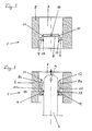
- Fig. 1 shows a central longitudinal section through a Closure element according to the invention, which as a whole with the reference numeral 1 is provided. This is from below in the Through opening of a tubular liquid outlet 2 used, which preferably the ink outlet one in forms additional ink cartridge, not shown.
- a tubular liquid outlet 2 used, which preferably the ink outlet one in forms additional ink cartridge, not shown.
- This representation and the detailed view in Figure 2, in which the section that is rotated by 90 ° around the longitudinal axis shows that pierceable closure element 1 in unused, d. H. yet not for punctured fluid withdrawal.
- FIG. 3 is a hollow needle Liquid withdrawal referred, preferably the one Ink-jet printing system installed. This is at its top in the drawing relatively blunt and with lateral Provide removal openings 4. With the arrow is in Fig. 1 and Fig. 3 shows the piercing direction when the Ink cartridge with its liquid outlet 2 in it Inkjet printing system is used.
- the closure element 1 is in one piece with all components made of thermoplastic elastomer or Made of rubber material. It essentially comprises one tubular section-shaped fastener 5, which in the Representation from below in the passage of the Liquid outlet 2 can be used sealingly and there by means of circumferential locking projections 6 in corresponding grooves is positively fixed in the liquid outlet 2.
- the receiving space in the closure element 1, in which the Hollow needle 3 is pierceable, this is the through Fastening element 5 continuous liquid extraction channel 7, is in the intact state according to FIG. 1 or FIG. 2 closed an arrangement according to the invention.
- This includes a central, circular disk-shaped piercing area 8, the one with the inner edge of a circumferential one Sealing bead 9 is connected, which is the inventive Sealing profile forms.
- the diameter of the Piercing area 8 approximately the same size or slightly larger designed as the diameter of the hollow needle 3. Thereby reaches the tip of the hollow needle 3 during the piercing process first in contact with the bottom of the piercing area 8, with radial play to the sealing bead 9.
- connection area 11 where the piercing area 8 to the is formed on the inner edge of the sealing bead 9 is the bevel reduces the material thickness, so there a kind of circumferential film hinge between the material of the Piercing area 8 and the sealing bead 9 is formed.
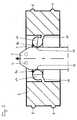
- FIG. 3 shows the same view as Fig. 2.
- the hollow needle 3 is shown in the Views in the direction of the arrow from the bottom up first to against the underside of the piercing area 8.
- the Continuation of this piercing movement leads to the fact that the Piercing area 8 at the depression 10 and the Entry of the hollow needle 3 in the through opening 7 releases.
- the separate sections of the Piercing area 8, which is indicated in FIG. 3 by the reference symbol 8a are provided by the penetrating hollow needle 3 pushed radially outwards in a swivel motion, what in Fig.
- FIG. 3 shows here clearly that those provided with the reference number 12 Crack edges of the areas 8a of the piercing area 8, which have previously been in the area of the recess 10, not for Seal the hollow needle 3 contribute.
- the seal on the Rather, the outer circumference of the hollow needle 3 is according to the invention thereby achieved that the sealing bead 9 at Piercing process by bending the partial areas 8a of the Piercing area 8 wraps around a circumferential line in a toroidal shape will, d. H. is twisted around a circumferential line.
- the function of the sealing bead 9 is a synopsis 2 and 3 clearly recognizable.
- 2 are located the areas serving as sealing surfaces 13 on the Outside of the sealing bead first outside the Piercing area 8.
- the passage cross-section also narrows inside the sealing bead 9, so that by the circumferential Sealing surface 13 which, in contrast to the tear edges 12 has a defined, smooth sealing surface, an optimized Sealing the hollow needle 3 in the closure element 1 is achieved.
- FIG. 3 shows that the Sealing bead 9 in the inserted state of the hollow needle 3 in Area of the piercing opening approximately the shape of an O-ring who assumes a particularly good seal for the Hollow needle 3 forms.
- the previously known pierceable closure elements which in the arrangement with a pierceable sealing film from the start separate O-rings are formed by the special design according to the invention an O-ring-like Sealing element only when the hollow needle 3 is inserted out.
- the advantage of the pierceable invention Closure element 1 is that it is in one piece and thus particularly inexpensive to manufacture and easy to assemble is. The seal is clear compared to one also easy to manufacture septum improved.
- FIG. 4 and 5 show a closure element 1 according to the invention in a second embodiment, being the same Functional elements use the same reference numerals as in the previous illustrations.
- 4 shows analogous to Fig. 2 again the unused, d. H. intact State, while Fig. 5, analogous to Fig. 3, the operating state shows with a pierced hollow needle 3.
Landscapes
- Ink Jet (AREA)
- Closures For Containers (AREA)
- Pens And Brushes (AREA)
Applications Claiming Priority (2)
| Application Number | Priority Date | Filing Date | Title |
|---|---|---|---|
| DE10100171 | 2001-01-04 | ||
| DE10100171A DE10100171B4 (de) | 2001-01-04 | 2001-01-04 | Durchstechbares Verschlusselement und Tintenbehälter mit durchstechbarem Verschlusselement |
Publications (3)
| Publication Number | Publication Date |
|---|---|
| EP1221376A2 true EP1221376A2 (fr) | 2002-07-10 |
| EP1221376A3 EP1221376A3 (fr) | 2003-01-29 |
| EP1221376B1 EP1221376B1 (fr) | 2006-08-30 |
Family
ID=7669747
Family Applications (1)
| Application Number | Title | Priority Date | Filing Date |
|---|---|---|---|
| EP01129673A Expired - Lifetime EP1221376B1 (fr) | 2001-01-04 | 2001-12-13 | Elément de fermeture perforable et réservoir d'encre muni d'un tel élement de fermeture perforable |
Country Status (5)
| Country | Link |
|---|---|
| US (1) | US6692118B2 (fr) |
| EP (1) | EP1221376B1 (fr) |
| AT (1) | ATE337917T1 (fr) |
| DE (2) | DE10100171B4 (fr) |
| ES (1) | ES2272399T3 (fr) |
Cited By (1)
| Publication number | Priority date | Publication date | Assignee | Title |
|---|---|---|---|---|
| WO2013015788A1 (fr) * | 2011-07-26 | 2013-01-31 | Hewlett-Packard Development Company, L.P. | Dispositif d'alimentation en fluide, diaphragme utilisable avec un dispositif d'alimentation en fluide et leur procédé |
Families Citing this family (34)
| Publication number | Priority date | Publication date | Assignee | Title |
|---|---|---|---|---|
| US7192127B2 (en) * | 2003-04-25 | 2007-03-20 | Canon Kabushiki Kaisha | Ink cartridge |
| DE102004003439B4 (de) * | 2004-01-22 | 2022-02-03 | Sata Gmbh & Co. Kg | Farbbechersystem für eine Farbspritzpistole |
| US7533976B2 (en) * | 2005-04-27 | 2009-05-19 | Hewlett-Packard Development Company, L.P. | Sealing component defining first, second, and third seals |
| US20070247499A1 (en) * | 2006-04-19 | 2007-10-25 | Anderson Jr James D | Multi-function thermoplastic elastomer layer for replaceable ink tank |
| DE502007000825D1 (de) | 2006-12-05 | 2009-07-16 | Sata Gmbh & Co Kg | Belüftung für den Fließbecher einer Farbspritzpistole |
| US8066358B2 (en) * | 2007-01-30 | 2011-11-29 | Hewlett-Packard Development Company, L.P. | Over-molded fluid interconnect |
| DE102007062681A1 (de) * | 2007-12-24 | 2009-06-25 | Man Turbo Ag | Dichtsegment sowie Dichtsegmentenanordnung |
| ES2537617T3 (es) | 2008-03-12 | 2015-06-10 | Jeffrey D. Fox | Cartucho desechable para pistola de pulverización |
| JP5203094B2 (ja) * | 2008-04-03 | 2013-06-05 | 矢崎総業株式会社 | コネクタ用パッキン構造 |
| EP2344337B1 (fr) * | 2008-10-15 | 2013-09-25 | Hewlett-Packard Development Company, L.P. | Cartouche d éjection de fluide |
| DE202008014389U1 (de) | 2008-10-29 | 2010-04-08 | Sata Gmbh & Co. Kg | Fließbecher für eine Farbspritzpistole |
| JP5435962B2 (ja) * | 2009-01-07 | 2014-03-05 | キヤノン株式会社 | 液体噴射記録ヘッド、及び液体噴射記録ヘッドの製造方法 |
| JP5493904B2 (ja) * | 2009-03-12 | 2014-05-14 | 株式会社リコー | 液体収容容器及び画像形成装置 |
| DE102009032399A1 (de) | 2009-07-08 | 2011-01-13 | Sata Gmbh & Co. Kg | Farbspritzpistole |
| DE202010007355U1 (de) | 2010-05-28 | 2011-10-20 | Sata Gmbh & Co. Kg | Düsenkopf für eine Spritzvorrichtung |
| US9333519B2 (en) | 2010-12-02 | 2016-05-10 | Sata Gmbh & Co. Kg | Spray gun and accessories |
| RU2601337C2 (ru) | 2011-06-30 | 2016-11-10 | САТА ГмбХ унд Ко. КГ | Пистолет-краскораспылитель с возможностью легкой очистки, принадлежности для пистолета-краскораспылителя и способ их монтажа и демонтажа |
| CA155474S (en) | 2013-09-27 | 2015-08-27 | Sata Gmbh & Co Kg | Spray gun |
| DE202013105779U1 (de) | 2013-12-18 | 2015-03-19 | Sata Gmbh & Co. Kg | Luftdüsenabschluss für eine Lackierpistole |
| US9332826B2 (en) | 2014-07-09 | 2016-05-10 | Ricky Spillman, JR. | Cleaning device |
| CN110560285B (zh) | 2014-07-31 | 2021-05-18 | 萨塔有限两合公司 | 喷枪及其制造方法 |
| CA159961S (en) | 2014-07-31 | 2015-07-17 | Sata Gmbh & Co Kg | Spray gun |
| USD758537S1 (en) | 2014-07-31 | 2016-06-07 | Sata Gmbh & Co. Kg | Paint spray gun rear portion |
| USD768820S1 (en) | 2014-09-03 | 2016-10-11 | Sata Gmbh & Co. Kg | Paint spray gun with pattern |
| DE102015006484A1 (de) | 2015-05-22 | 2016-11-24 | Sata Gmbh & Co. Kg | Düsenanordnung für eine Spritzpistole, insbesondere Farbspritzpistole und Spritzpistole, insbesondere Farbspritzpistole |
| DE102015016474A1 (de) | 2015-12-21 | 2017-06-22 | Sata Gmbh & Co. Kg | Luftkappe und Düsenanordnung für eine Spritzpistole und Spritzpistole |
| CN205995666U (zh) | 2016-08-19 | 2017-03-08 | 萨塔有限两合公司 | 喷枪及其扳机 |
| CN205966208U (zh) | 2016-08-19 | 2017-02-22 | 萨塔有限两合公司 | 风帽组件以及喷枪 |
| JP6803288B2 (ja) * | 2017-03-31 | 2020-12-23 | 理想科学工業株式会社 | インクジェット記録装置 |
| CN111936313A (zh) | 2018-05-15 | 2020-11-13 | 惠普发展公司,有限责任合伙企业 | 用于流体容器的出口机构 |
| DE102018118737A1 (de) | 2018-08-01 | 2020-02-06 | Sata Gmbh & Co. Kg | Düse für eine Spritzpistole, Düsensatz für eine Spritzpistole, Spritzpistolen und Verfahren zur Herstellung einer Düse für eine Spritzpistole |
| US11826771B2 (en) | 2018-08-01 | 2023-11-28 | Sata Gmbh & Co. Kg | Set of nozzles for a spray gun, spray gun system, method for embodying a nozzle module, method for selecting a nozzle module from a set of nozzles for a paint job, selection system and computer program product |
| DE102018118738A1 (de) | 2018-08-01 | 2020-02-06 | Sata Gmbh & Co. Kg | Grundkörper für eine Spritzpistole, Spritzpistolen, Spritzpistolen-Set, Verfahren zur Herstellung eines Grundkörpers für eine Spritzpistole und Verfahren zum Umrüsten einer Spritzpistole |
| EP3679970A1 (fr) * | 2019-01-11 | 2020-07-15 | Roche Diabetes Care GmbH | Berceau pour une unité de pompe à perfusion |
Citations (4)
| Publication number | Priority date | Publication date | Assignee | Title |
|---|---|---|---|---|
| DE19534577A1 (de) * | 1994-09-16 | 1996-03-28 | Seiko Epson Corp | Tintenstrahldrucker, Tintenpatrone für Tintenstrahldrucker sowie System und Verfahren zur Tintenzufuhr |
| EP0745480A2 (fr) * | 1995-05-16 | 1996-12-04 | Dynamic Cassette International Limited | Cartouche d'encre pour imprimante à jet d'encre |
| US5907341A (en) * | 1993-05-11 | 1999-05-25 | Seiko Epson Corporation | Ink cartridge for printer |
| EP1000753A1 (fr) * | 1998-11-11 | 2000-05-17 | Seiko Epson Corporation | Appareil d'impression à jet d'encre et cartouche d'encre |
Family Cites Families (5)
| Publication number | Priority date | Publication date | Assignee | Title |
|---|---|---|---|---|
| US4516967A (en) * | 1981-12-21 | 1985-05-14 | Kopfer Rudolph J | Wet-dry compartmental syringe |
| DE19534578C2 (de) * | 1994-09-16 | 2000-01-20 | Seiko Epson Corp | Tintenpatrone |
| US6238042B1 (en) * | 1994-09-16 | 2001-05-29 | Seiko Epson Corporation | Ink cartridge for ink jet printer and method of charging ink into said cartridge |
| DE19849567B4 (de) * | 1998-10-27 | 2004-02-12 | Tally Computerdrucker Gmbh | Tintendrucker mit einer Wechselkartusche für Tintenflüssigkeit |
| DE19962662B4 (de) * | 1999-12-23 | 2005-12-01 | 3T Supplies Ag | Tintenkassette und Verfahren zum Herstellen einer Tintenkassette |
-
2001
- 2001-01-04 DE DE10100171A patent/DE10100171B4/de not_active Expired - Fee Related
- 2001-12-13 AT AT01129673T patent/ATE337917T1/de not_active IP Right Cessation
- 2001-12-13 ES ES01129673T patent/ES2272399T3/es not_active Expired - Lifetime
- 2001-12-13 EP EP01129673A patent/EP1221376B1/fr not_active Expired - Lifetime
- 2001-12-13 DE DE50110871T patent/DE50110871D1/de not_active Expired - Lifetime
- 2001-12-31 US US10/032,158 patent/US6692118B2/en not_active Expired - Fee Related
Patent Citations (4)
| Publication number | Priority date | Publication date | Assignee | Title |
|---|---|---|---|---|
| US5907341A (en) * | 1993-05-11 | 1999-05-25 | Seiko Epson Corporation | Ink cartridge for printer |
| DE19534577A1 (de) * | 1994-09-16 | 1996-03-28 | Seiko Epson Corp | Tintenstrahldrucker, Tintenpatrone für Tintenstrahldrucker sowie System und Verfahren zur Tintenzufuhr |
| EP0745480A2 (fr) * | 1995-05-16 | 1996-12-04 | Dynamic Cassette International Limited | Cartouche d'encre pour imprimante à jet d'encre |
| EP1000753A1 (fr) * | 1998-11-11 | 2000-05-17 | Seiko Epson Corporation | Appareil d'impression à jet d'encre et cartouche d'encre |
Cited By (3)
| Publication number | Priority date | Publication date | Assignee | Title |
|---|---|---|---|---|
| WO2013015788A1 (fr) * | 2011-07-26 | 2013-01-31 | Hewlett-Packard Development Company, L.P. | Dispositif d'alimentation en fluide, diaphragme utilisable avec un dispositif d'alimentation en fluide et leur procédé |
| US9738078B2 (en) | 2011-07-26 | 2017-08-22 | Hewlett-Packard Development Company, L.P. | Fluid supply device, septum device usable with fluid supply device and method thereof |
| US10099480B2 (en) | 2011-07-26 | 2018-10-16 | Hewlett-Packard Development Company, L.P. | Fluid supply device, septum device usable with fluid supply device and method thereof |
Also Published As
| Publication number | Publication date |
|---|---|
| EP1221376B1 (fr) | 2006-08-30 |
| ATE337917T1 (de) | 2006-09-15 |
| US20020084596A1 (en) | 2002-07-04 |
| US6692118B2 (en) | 2004-02-17 |
| DE50110871D1 (de) | 2006-10-12 |
| EP1221376A3 (fr) | 2003-01-29 |
| DE10100171A1 (de) | 2002-07-25 |
| DE10100171B4 (de) | 2005-02-24 |
| ES2272399T3 (es) | 2007-05-01 |
Similar Documents
| Publication | Publication Date | Title |
|---|---|---|
| EP1221376B1 (fr) | Elément de fermeture perforable et réservoir d'encre muni d'un tel élement de fermeture perforable | |
| EP1140259B1 (fr) | Ampoule multichambre servant a distribuer un melange constitue de plusieurs substances | |
| DE68927896T2 (de) | Vorgeschlitzte Injektionsstelle und Spritz zulaufende Kanüle | |
| DE3809127C1 (fr) | ||
| DE69822495T2 (de) | Nadellose injektionsstelle | |
| EP2667838B1 (fr) | Dispositif de liaison destiné à relier un premier réservoir à un deuxième réservoir | |
| EP1032446B2 (fr) | Configuration d'aiguille | |
| DE69920365T2 (de) | Selbsthaltende Nadelanordnung und darin anzuwendendes Ventilelement | |
| EP1844710B1 (fr) | Lancette pour perforer la peau | |
| DE69104143T2 (de) | Infusionsvorrichtung für Flüssigkeiten. | |
| EP0912209B1 (fr) | Tete de seringue d'injection a fermeture anti-reutilisation | |
| DE3006291A1 (de) | Intravaskulaer-kathetervorrichtung | |
| EP1454650A1 (fr) | Dispositif de transfer, notamment pour des fluides médicaux | |
| DE3732515A1 (de) | Vorrichtung zum einspritzen und/oder entnehmen von fluessigkeiten | |
| DE1566053A1 (de) | Ventileinrichtung,insbesondere an Blutentnahmegeraeten | |
| DE2258372B2 (de) | Füllbare Spritze | |
| EP2520360A1 (fr) | Mélangeur destiné à mélanger au moins deux composants pouvant s'écouler ainsi que dispositif de sortie | |
| DE102015201285B3 (de) | Vorrichtung zum Überführen einer Flüssigkeit zwischen einem Lagerbehälter und mindestens einem weiteren Gebrauchsbehälter sowie Set aus Überführungsvorrichtung und Lagerbehälter | |
| EP0419490B1 (fr) | Dispositif de fermeture pour recipients cylindriques se pretant notamment au vide | |
| WO2018127267A1 (fr) | Contenant | |
| EP1900652A1 (fr) | Conteneur | |
| DE19858715B4 (de) | Entnahmevorrichtung zur festen Anordnung auf dem geschlossen ausgebildeten Behälterhals eines Medikamenten-, insbesondere Infusionsbehälters | |
| EP3034062A1 (fr) | Système de connecteur ayant au moins deux ports de prélèvement | |
| DE102004044288A1 (de) | Vorrichtung zur Verbindung eines rohrförmigen Teils, insbesondere einer Kanüle, mit dem Inneren einer Flasche oder dergleichen | |
| DE102015201288B4 (de) | Hohlnadel-Baugruppe |
Legal Events
| Date | Code | Title | Description |
|---|---|---|---|
| PUAI | Public reference made under article 153(3) epc to a published international application that has entered the european phase |
Free format text: ORIGINAL CODE: 0009012 |
|
| AK | Designated contracting states |
Kind code of ref document: A2 Designated state(s): AT BE CH CY DE DK ES FI FR GB GR IE IT LI LU MC NL PT SE TR |
|
| AX | Request for extension of the european patent |
Free format text: AL;LT;LV;MK;RO;SI |
|
| PUAL | Search report despatched |
Free format text: ORIGINAL CODE: 0009013 |
|
| AK | Designated contracting states |
Designated state(s): AT BE CH CY DE DK ES FI FR GB GR IE IT LI LU MC NL PT SE TR |
|
| AX | Request for extension of the european patent |
Extension state: AL LT LV MK RO SI |
|
| 17P | Request for examination filed |
Effective date: 20030602 |
|
| AKX | Designation fees paid |
Designated state(s): AT BE CH CY DE DK ES FI FR GB GR IE IT LI LU MC NL PT SE TR |
|
| 17Q | First examination report despatched |
Effective date: 20040407 |
|
| GRAP | Despatch of communication of intention to grant a patent |
Free format text: ORIGINAL CODE: EPIDOSNIGR1 |
|
| RAP1 | Party data changed (applicant data changed or rights of an application transferred) |
Owner name: ARTECH GMBHDESIGN + PRODUCTION IN PLASTIC |
|
| GRAS | Grant fee paid |
Free format text: ORIGINAL CODE: EPIDOSNIGR3 |
|
| GRAA | (expected) grant |
Free format text: ORIGINAL CODE: 0009210 |
|
| AK | Designated contracting states |
Kind code of ref document: B1 Designated state(s): AT BE CH CY DE DK ES FI FR GB GR IE IT LI LU MC NL PT SE TR |
|
| PG25 | Lapsed in a contracting state [announced via postgrant information from national office to epo] |
Ref country code: FI Free format text: LAPSE BECAUSE OF FAILURE TO SUBMIT A TRANSLATION OF THE DESCRIPTION OR TO PAY THE FEE WITHIN THE PRESCRIBED TIME-LIMIT Effective date: 20060830 Ref country code: IE Free format text: LAPSE BECAUSE OF FAILURE TO SUBMIT A TRANSLATION OF THE DESCRIPTION OR TO PAY THE FEE WITHIN THE PRESCRIBED TIME-LIMIT Effective date: 20060830 Ref country code: NL Free format text: LAPSE BECAUSE OF FAILURE TO SUBMIT A TRANSLATION OF THE DESCRIPTION OR TO PAY THE FEE WITHIN THE PRESCRIBED TIME-LIMIT Effective date: 20060830 |
|
| REG | Reference to a national code |
Ref country code: GB Ref legal event code: FG4D Free format text: NOT ENGLISH |
|
| REG | Reference to a national code |
Ref country code: CH Ref legal event code: EP |
|
| REG | Reference to a national code |
Ref country code: IE Ref legal event code: FG4D Free format text: LANGUAGE OF EP DOCUMENT: GERMAN |
|
| REF | Corresponds to: |
Ref document number: 50110871 Country of ref document: DE Date of ref document: 20061012 Kind code of ref document: P |
|
| PG25 | Lapsed in a contracting state [announced via postgrant information from national office to epo] |
Ref country code: DK Free format text: LAPSE BECAUSE OF FAILURE TO SUBMIT A TRANSLATION OF THE DESCRIPTION OR TO PAY THE FEE WITHIN THE PRESCRIBED TIME-LIMIT Effective date: 20061130 Ref country code: SE Free format text: LAPSE BECAUSE OF FAILURE TO SUBMIT A TRANSLATION OF THE DESCRIPTION OR TO PAY THE FEE WITHIN THE PRESCRIBED TIME-LIMIT Effective date: 20061130 |
|
| PG25 | Lapsed in a contracting state [announced via postgrant information from national office to epo] |
Ref country code: BE Free format text: LAPSE BECAUSE OF NON-PAYMENT OF DUE FEES Effective date: 20061231 Ref country code: CH Free format text: LAPSE BECAUSE OF NON-PAYMENT OF DUE FEES Effective date: 20061231 Ref country code: LI Free format text: LAPSE BECAUSE OF NON-PAYMENT OF DUE FEES Effective date: 20061231 Ref country code: MC Free format text: LAPSE BECAUSE OF NON-PAYMENT OF DUE FEES Effective date: 20061231 |
|
| PG25 | Lapsed in a contracting state [announced via postgrant information from national office to epo] |
Ref country code: PT Free format text: LAPSE BECAUSE OF FAILURE TO SUBMIT A TRANSLATION OF THE DESCRIPTION OR TO PAY THE FEE WITHIN THE PRESCRIBED TIME-LIMIT Effective date: 20070212 |
|
| NLV1 | Nl: lapsed or annulled due to failure to fulfill the requirements of art. 29p and 29m of the patents act | ||
| ET | Fr: translation filed | ||
| REG | Reference to a national code |
Ref country code: IE Ref legal event code: FD4D |
|
| REG | Reference to a national code |
Ref country code: ES Ref legal event code: FG2A Ref document number: 2272399 Country of ref document: ES Kind code of ref document: T3 |
|
| PLBE | No opposition filed within time limit |
Free format text: ORIGINAL CODE: 0009261 |
|
| STAA | Information on the status of an ep patent application or granted ep patent |
Free format text: STATUS: NO OPPOSITION FILED WITHIN TIME LIMIT |
|
| 26N | No opposition filed |
Effective date: 20070531 |
|
| REG | Reference to a national code |
Ref country code: CH Ref legal event code: PL |
|
| BERE | Be: lapsed |
Owner name: ARTECH G.M.B.H. DESIGN + PRODUCTION IN PLASTIC Effective date: 20061231 |
|
| PG25 | Lapsed in a contracting state [announced via postgrant information from national office to epo] |
Ref country code: AT Free format text: LAPSE BECAUSE OF NON-PAYMENT OF DUE FEES Effective date: 20061213 |
|
| PG25 | Lapsed in a contracting state [announced via postgrant information from national office to epo] |
Ref country code: GR Free format text: LAPSE BECAUSE OF FAILURE TO SUBMIT A TRANSLATION OF THE DESCRIPTION OR TO PAY THE FEE WITHIN THE PRESCRIBED TIME-LIMIT Effective date: 20061201 |
|
| PG25 | Lapsed in a contracting state [announced via postgrant information from national office to epo] |
Ref country code: LU Free format text: LAPSE BECAUSE OF NON-PAYMENT OF DUE FEES Effective date: 20061213 Ref country code: TR Free format text: LAPSE BECAUSE OF FAILURE TO SUBMIT A TRANSLATION OF THE DESCRIPTION OR TO PAY THE FEE WITHIN THE PRESCRIBED TIME-LIMIT Effective date: 20060830 |
|
| PG25 | Lapsed in a contracting state [announced via postgrant information from national office to epo] |
Ref country code: CY Free format text: LAPSE BECAUSE OF FAILURE TO SUBMIT A TRANSLATION OF THE DESCRIPTION OR TO PAY THE FEE WITHIN THE PRESCRIBED TIME-LIMIT Effective date: 20060830 |
|
| REG | Reference to a national code |
Ref country code: FR Ref legal event code: PLFP Year of fee payment: 15 |
|
| REG | Reference to a national code |
Ref country code: FR Ref legal event code: PLFP Year of fee payment: 16 |
|
| PGFP | Annual fee paid to national office [announced via postgrant information from national office to epo] |
Ref country code: GB Payment date: 20161222 Year of fee payment: 16 |
|
| PGFP | Annual fee paid to national office [announced via postgrant information from national office to epo] |
Ref country code: ES Payment date: 20161221 Year of fee payment: 16 Ref country code: IT Payment date: 20161220 Year of fee payment: 16 Ref country code: FR Payment date: 20161221 Year of fee payment: 16 |
|
| PGFP | Annual fee paid to national office [announced via postgrant information from national office to epo] |
Ref country code: DE Payment date: 20161220 Year of fee payment: 16 |
|
| REG | Reference to a national code |
Ref country code: DE Ref legal event code: R119 Ref document number: 50110871 Country of ref document: DE |
|
| GBPC | Gb: european patent ceased through non-payment of renewal fee |
Effective date: 20171213 |
|
| REG | Reference to a national code |
Ref country code: FR Ref legal event code: ST Effective date: 20180831 |
|
| PG25 | Lapsed in a contracting state [announced via postgrant information from national office to epo] |
Ref country code: IT Free format text: LAPSE BECAUSE OF NON-PAYMENT OF DUE FEES Effective date: 20171213 Ref country code: DE Free format text: LAPSE BECAUSE OF NON-PAYMENT OF DUE FEES Effective date: 20180703 Ref country code: FR Free format text: LAPSE BECAUSE OF NON-PAYMENT OF DUE FEES Effective date: 20180102 |
|
| PG25 | Lapsed in a contracting state [announced via postgrant information from national office to epo] |
Ref country code: GB Free format text: LAPSE BECAUSE OF NON-PAYMENT OF DUE FEES Effective date: 20171213 |
|
| REG | Reference to a national code |
Ref country code: ES Ref legal event code: FD2A Effective date: 20190703 |
|
| PG25 | Lapsed in a contracting state [announced via postgrant information from national office to epo] |
Ref country code: ES Free format text: LAPSE BECAUSE OF NON-PAYMENT OF DUE FEES Effective date: 20171214 |