EP1221362A2 - Einstellbares Schneidwerkzeug zum Umformen eines Werkstücks - Google Patents
Einstellbares Schneidwerkzeug zum Umformen eines Werkstücks Download PDFInfo
- Publication number
- EP1221362A2 EP1221362A2 EP02000110A EP02000110A EP1221362A2 EP 1221362 A2 EP1221362 A2 EP 1221362A2 EP 02000110 A EP02000110 A EP 02000110A EP 02000110 A EP02000110 A EP 02000110A EP 1221362 A2 EP1221362 A2 EP 1221362A2
- Authority
- EP
- European Patent Office
- Prior art keywords
- spacer elements
- drive shaft
- cutter
- workpiece
- cutter members
- Prior art date
- Legal status (The legal status is an assumption and is not a legal conclusion. Google has not performed a legal analysis and makes no representation as to the accuracy of the status listed.)
- Withdrawn
Links
Images


Classifications
-
- B—PERFORMING OPERATIONS; TRANSPORTING
- B27—WORKING OR PRESERVING WOOD OR SIMILAR MATERIAL; NAILING OR STAPLING MACHINES IN GENERAL
- B27G—ACCESSORY MACHINES OR APPARATUS FOR WORKING WOOD OR SIMILAR MATERIALS; TOOLS FOR WORKING WOOD OR SIMILAR MATERIALS; SAFETY DEVICES FOR WOOD WORKING MACHINES OR TOOLS
- B27G13/00—Cutter blocks; Other rotary cutting tools
- B27G13/005—Tools composed of two or more rotating discs
- B27G13/007—Tools composed of two or more rotating discs which are adjustable relatively to each other
-
- B—PERFORMING OPERATIONS; TRANSPORTING
- B27—WORKING OR PRESERVING WOOD OR SIMILAR MATERIAL; NAILING OR STAPLING MACHINES IN GENERAL
- B27G—ACCESSORY MACHINES OR APPARATUS FOR WORKING WOOD OR SIMILAR MATERIALS; TOOLS FOR WORKING WOOD OR SIMILAR MATERIALS; SAFETY DEVICES FOR WOOD WORKING MACHINES OR TOOLS
- B27G13/00—Cutter blocks; Other rotary cutting tools
- B27G13/12—Cutter blocks; Other rotary cutting tools for profile cutting
- B27G13/14—Cutter blocks; Other rotary cutting tools for profile cutting for cutting grooves or tenons
-
- Y—GENERAL TAGGING OF NEW TECHNOLOGICAL DEVELOPMENTS; GENERAL TAGGING OF CROSS-SECTIONAL TECHNOLOGIES SPANNING OVER SEVERAL SECTIONS OF THE IPC; TECHNICAL SUBJECTS COVERED BY FORMER USPC CROSS-REFERENCE ART COLLECTIONS [XRACs] AND DIGESTS
- Y10—TECHNICAL SUBJECTS COVERED BY FORMER USPC
- Y10T—TECHNICAL SUBJECTS COVERED BY FORMER US CLASSIFICATION
- Y10T409/00—Gear cutting, milling, or planing
- Y10T409/30—Milling
- Y10T409/30952—Milling with cutter holder
Definitions
- the present invention related generally to router bits for forming a workpiece, and more particularly to bits of this type that are designed to form tongues and grooves in the workpiece.
- a rotating bit which includes two cutter elements fixed onto a drive shaft, and the rotating bit is moved laterally into contact with the edge of the workpiece to be formed.
- the bit includes two cutter members fixed thereon at a spacing corresponding to the thickness of the tongue to be formed so that the edge of the workpiece is cut away by the cutter elements above and below the portion that becomes the tongue.
- the bit includes a single cutter member having a thickness corresponding to the desired thickness of the groove.
- each of the cutter elements is fixed to the drive shaft, and therefore each bit can only cut a tongue or groove having one specific thickness. Therefore, in applications where it is necessary to form workpieces with grooves and tongues having varying thicknesses, it is necessary to have in stock a large inventory of bits, each being capable of cutting one groove or tongue thickness within the range of desired thicknesses. Obviously, this can significantly increase the expense of the workshop in acquiring and maintaining the required number of bits that may be necessary for the particular operations of the workshop.
- each of the cutter members has a fixed axial thickness, and when the thickness of the tongue or groove to be formed is determined, the operator selects the two particular cutter members that will provide the desired thickness, and then mounts these two cutter members on the drive shaft.
- This arrangement is an improvement over the above-described practice of maintaining a large number of different bits in stock, but it also has a similar disadvantage in that it requires the workshop to maintain in inventory a large number of cutter elements of varying sizes that can be mounted on the drive shaft to form a tongue or groove of a desired thickness.
- this arrangement has a further disadvantage in that the size of the replaceable cutter members makes it difficult for any two of them to be mounted on the drive shaft with the required axial tolerance needed to form a tongue or groove of a specific axial thickness.
- the present invention provides an adjustable bit for cutting tongues or grooves in a wooden workpiece which includes an axially extending drive shaft, a first cutter member mounted on the drive shaft and movable along the axial length thereof, and a second cutter member mounted on the shaft and movable along the axial length thereof.
- a plurality of spacer elements are selectively mountable on the shaft intermediate the first and second cutter members to vary the axial spacing therebetween.
- a cap member is removably mounted on the drive shaft to permit at least one of the cutter members to be mounted on and removed from the shaft, and to permit one or more of the spacer elements to be mounted on and removed from the shaft, and the cap member has a fixed position thereon for holding in place the first and second cutter members and the spacer elements therebetween, whereby the adjustable bit can be used to cut grooves or tongues of varying thicknesses in the workpiece.
- the spacer elements have different axial thicknesses, and there may be nine of the spacer elements mountable on the drive shaft, with some of the spacer elements having the same axial thickness and some of the spacer elements have axial thicknesses which are different from other spacer elements. More particularly, it is preferred that four of the spacer elements have an axial thickness of 1 mm; two of the spacer elements have an axial thickness of .2 mm; and three of the spacer elements have an axial thickness of .5 mm, .15 mm and .1 mm, respectively.
- the cutter members, the spacer elements and the cap member be stacked on the drive shaft with the first cutter members being in the lowermost position, with at least some of the spacer elements on top of the first cutter member, with the second cutter members being on top of the spacer elements, and with the cap member fixed in place on the shaft above the second cutter member.
- the spacer elements may be arranged so that some of them are located between the first and second cutter members to provide the desired spacing therebetween, and any remaining spacer elements can be conveniently carried above the second cutter member and between the second cutter member and the cap member.
- the first and second cutter members are formed to cut a tongue in the workpiece.
- the spacer elements preferably include a ball bearing pilot member disposed between the first and second cutter members to provide a guide surface for the workpiece as it is being cut by the adjustable bit, and the spacer elements also include a plurality of shims, at least some of which are mounted on the drive shaft between the ball bearing pilot member and at least one of the first and second cutter members.
- the first and second members are formed to cut a groove in the workpiece, and in this embodiment the first and second cutter members are provided with cutting blades that are capable of overlapping one another in the axial direction whereby grooves of different depths can be cut using the same cutter members and the aforesaid spacer elements.
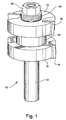
- Figs. 1 and 2 illustrate an adjustable bit 10 according to one embodiment of the present invention.
- the bit 10 includes a general cylindrical drive shaft 12 formed with a shoulder 14.
- the upper end of the drive shaft 12 extends upwardly through a first cutter member 16 that has a cutting blade 18 fixed at its outer periphery in a conventional manner.
- the drive shaft 12 also extends through a second cutter member 20 having a peripheral cutting blade 22, and, intermediate the first and second cutter members 16 and 20, a spacer member in the form of a ball bearing pilot member 24 is mounted for rotation relative to the drive shaft 10.
- a plurality of spacer elements in the form of shims 26 are disposed above the second cutter member 20, and a cap member 28, which is preferably a threaded nut, is threaded onto the top end of the drive shaft 10 and fixed in place thereon to securely hold in place the first and second cutter member 16, 20, the ball bearing pilot member 24, and the shims 26.
- the ball bearing pilot member 24 acts as a spacer element to separate the first and second cutter members 16, 20 by an axial dimension corresponding to the axial thickness of the ball bearing pilot member 24. Accordingly, with the several elements held in place as described above, it will be seen in Fig. 2 that the bit 10 can be used to cut a tongue 28 in a wooden work piece 30, and the tongue 28 has a particular, desired thickness or depth, depending on the axial thickness of the ball bearing pilot member 24 and the size and location of the blades 18, 22 on the first and second cutter member 16, 20.
- the extending end face of the tongue 28 abuts the other periphery of the ball bearing pilot member 24 so that the ball bearing pilot member 24 establishes a consistent extending dimension for the tongue 28 after it is cut, and since the pilot member 24 is rotatably mounted on the drive shaft 12, there is little or no frictional resistance between the end face of the tongue 28 and the exterior surface of the pilot member 24.
- the work piece thirty is formed with a tongue 28 as illustrated in Fig. 2A that has a precise thickness, and a precise extending length.
- the same components as those described above can be readily rearranged to vary the thickness of the tongue 28 cut by the bit 10. More specifically, if the nut 32 is removed from the threaded upper end of the drive shaft 12, the shims 26, the second cutter member 20, and the ball bearing pilot member 24 can be easily removed from the drive shaft 12 by sliding them upwardly. Depending on the desire depth of the new tongue 28 to be cut, all of these components can then be rearranged in a variety of different configuration to provide the desired depth for the tongue 28.
- FIG. 3 An example of one such configuration is illustrated in Fig. 3.
- the first cutter member 16 is positioned on the shoulder 14 of the drive shaft 12, and a desired number of shims 26 are slid onto the drive shaft 12, then the ball bearing pilot member 14 is placed on top of the first group of shims 26, and then a second group of shims 26 is placed on top of the ball bearing pilot member 24.
- the second cutter member 20 is then slidably mounted on the drive shaft 12 with any remaining shims 26 disposed on top of the second cutter member 20, and the cap member 32 is threaded onto the drive shaft 12 to hold all of the components securely in place.
- the depth or thickness of the tongue 28 is increased in Fig. 3 by a dimension corresponding to the collective axial thickness of the shims 26 that are positioned above and below the ball bearing pilot member 24.
- the tongue cut by the configuration by the bit illustrated in Fig. 3 is shown in Fig. 3A.
- any shims 26 that are not being used as spacer elements for the first and second cutter members 16, 20 are conveniently stored between the upper surface of the second cutter member 20 and the nut 32.
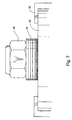
- the number of shims 26 provided with a particular bit 10, and the axial thicknesses of the shims 26, can be varied over a wide range, depending on the particular application of the bit 10.
- a group of nine shims 26 provide a particularly desirable range of tongue-cutting variations.
- four of the shims 26 have an axial thickness of 1 mm
- two of the shims have an axial thickness of .2 mm
- the remaining three shims 26 have axial thicknesses of .5 mm, .15 mm, and .1 mm, respectively.
- This representative collection of shims 26 is illustrated in Fig. 7 with all of the shims 26 in their stored position between the upper surface and the second cutter member 20 and the nut 32.
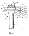
- the adjustable bit 10 of the present invention may also be used to cut grooves 34 in the work piece 28 using a configuration of elements as best illustrated in Figs. 4, 5 and 6.
- the first and second cutters 16, 20 have cutter blades 18, 22 mounted at the periphery thereof as described above.
- the adjustable bit 10 can be used to cut a groove 34 in the work piece 28 which has a thickness or depth that is less than the combined axial thicknesses of the cutting blades 18, 22.
- the groove 34 cut with this configuration is illustrated in Fig. 5A, and it will also be noted that in this configuration the ball bearing pilot member 24 and all of the shims 26 are slidably mounted on the drive shaft 12 above the second cutter member 20, and they are held in place by the nut 32.
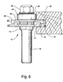
- the nut 32 is removed along with the ball bearing pilot member 24 and the shims 26, and these components are then placed on the drive shaft 12 with a new arrangement in which a desired number of the shims 26 are disposed between the first and second cutter member 16, 20 as best illustrated in Fig. 6.
- the cutter blades 18, 22 are still partially overlapped or immediately adjacent one another in the axial direction so that the enlarged groove 34 can be readily cut by the adjustable bit 10.
- the enlarged groove 34 cut by the adjustable bit illustrated in Fig. 6 is shown in Fig. 6A.
- the present invention provides an adjustable bit 10 that can be used for cutting a tongue 28 or a groove 34 in a work piece 30, and requires only a simple tool for removing the nut 32 to permit the adjustable bit 10 to be adjusted to a wide variety of cutting depths, all without requiring any inventory of different sized cutting members. Moreover, all of the necessary components for varying the cut are readily carried on the drive shaft 12, either in a position to act as a spacer element or conveniently stored at the top of the adjustable bit 10.
Landscapes
- Life Sciences & Earth Sciences (AREA)
- Engineering & Computer Science (AREA)
- Mechanical Engineering (AREA)
- Wood Science & Technology (AREA)
- Forests & Forestry (AREA)
- Milling, Drilling, And Turning Of Wood (AREA)
- Details Of Cutting Devices (AREA)
- Dovetailed Work, And Nailing Machines And Stapling Machines For Wood (AREA)
Applications Claiming Priority (2)
| Application Number | Priority Date | Filing Date | Title |
|---|---|---|---|
| US09/756,571 US6367524B1 (en) | 2001-01-08 | 2001-01-08 | Adjustable bit for forming a workpiece |
| US756571 | 2001-01-08 |
Publications (2)
| Publication Number | Publication Date |
|---|---|
| EP1221362A2 true EP1221362A2 (de) | 2002-07-10 |
| EP1221362A3 EP1221362A3 (de) | 2004-06-02 |
Family
ID=25044072
Family Applications (1)
| Application Number | Title | Priority Date | Filing Date |
|---|---|---|---|
| EP02000110A Withdrawn EP1221362A3 (de) | 2001-01-08 | 2002-01-03 | Einstellbares Schneidwerkzeug zum Umformen eines Werkstücks |
Country Status (3)
| Country | Link |
|---|---|
| US (1) | US6367524B1 (de) |
| EP (1) | EP1221362A3 (de) |
| CA (1) | CA2366684C (de) |
Cited By (2)
| Publication number | Priority date | Publication date | Assignee | Title |
|---|---|---|---|---|
| CN104057501A (zh) * | 2014-07-02 | 2014-09-24 | 浙江浪潮精密机械有限公司 | 一种加工橱柜门框的套装铣刀及其制造方法 |
| US11692578B2 (en) | 2018-09-26 | 2023-07-04 | Illinois Tool Works Inc. | Post-to-beam fastener |
Families Citing this family (25)
| Publication number | Priority date | Publication date | Assignee | Title |
|---|---|---|---|---|
| US6887017B2 (en) * | 2001-10-18 | 2005-05-03 | Donald Edward Klesser | Self-guided trim tool and method |
| US6568442B1 (en) * | 2001-11-28 | 2003-05-27 | Joseph Anthony Meugniot | Router bit for floorboard |
| US20030143039A1 (en) * | 2002-01-25 | 2003-07-31 | Dembicks Tyler J. | Router bit system |
| IL149909A0 (en) * | 2002-05-29 | 2002-12-01 | Dimar Ltd | A slotter having cutters with adjustable width |
| US6675849B1 (en) | 2003-02-19 | 2004-01-13 | Mark Lackley | Adjustable tenoning shim |
| US20040221922A1 (en) * | 2003-04-16 | 2004-11-11 | Hyde Brent K. | Box slotting router bit |
| US20050121107A1 (en) * | 2003-11-26 | 2005-06-09 | Lagerstrom Craig A. | Blade and apparatus configured for forming tenons |
| US10105773B1 (en) * | 2004-09-02 | 2018-10-23 | Robert Bosch Tool Corporation | Box joint blade system |
| US7198189B2 (en) * | 2004-09-28 | 2007-04-03 | Alcoa Inc. | Multi-shouldered fixed bobbin tools for simultaneous friction stir welding of multiple parallel walls between parts |
| US7131473B1 (en) * | 2005-07-19 | 2006-11-07 | Freud America, Inc. | Programmable coping bit |
| US7913729B2 (en) * | 2005-11-22 | 2011-03-29 | Anthony Brcich | Molding coping fixture |
| US7278806B1 (en) * | 2006-07-13 | 2007-10-09 | Clayton Stephen D | Two edge deburring tool |
| US20080041495A1 (en) * | 2006-08-18 | 2008-02-21 | George Vondriska | Tenon cutting router bit |
| US20080170917A1 (en) * | 2007-01-17 | 2008-07-17 | David Hilker | Dual cutter router bit |
| US20080217377A1 (en) * | 2007-03-06 | 2008-09-11 | Alcoa Inc. | Fracture Resistant Friction Stir Welding Tool |
| US20080302349A1 (en) * | 2007-06-07 | 2008-12-11 | Albert Badal | Stone thickness correcting tool for handheld machines |
| US7793816B2 (en) * | 2007-09-07 | 2010-09-14 | Alcoa Inc. | Friction stir welding apparatus |
| CN102943555B (zh) * | 2008-01-31 | 2014-12-31 | 瓦林格创新股份有限公司 | 与地板镶板的机械锁定和拆装相关的方法、设备和产品 |
| US7854362B2 (en) | 2008-03-14 | 2010-12-21 | Alcoa Inc. | Advanced multi-shouldered fixed bobbin tools for simultaneous friction stir welding of multiple parallel walls between parts |
| US20090245952A1 (en) * | 2008-03-31 | 2009-10-01 | Leslie Banduch | Bit with a cushion core |
| US8235080B2 (en) * | 2008-11-17 | 2012-08-07 | Lee Valley Tools, Ltd. | Interlocking, adjustable edge-forming router bit |
| US9079326B2 (en) * | 2010-03-15 | 2015-07-14 | Ainsworth Lumber Co. Ltd. | Profiling saw blade and method of using |
| FI20115432A (fi) * | 2011-05-06 | 2012-11-07 | Lennart Nordlund | Rakennusjärjestelmä |
| US20160008890A1 (en) * | 2013-07-29 | 2016-01-14 | John E. Rishton | Outside chamfering tool |
| CN113059225A (zh) * | 2021-04-01 | 2021-07-02 | 王梦娇 | 一种可回收连续型加工中心用刨板装置 |
Citations (6)
| Publication number | Priority date | Publication date | Assignee | Title |
|---|---|---|---|---|
| GB957307A (en) * | 1960-12-01 | 1964-05-06 | Duncan Edward Kent Grant | Spacer members for paper slitting and similar machines |
| FR2256807A1 (en) * | 1974-01-07 | 1975-08-01 | Merzeau Jean Alain | Woodworking tool forming slots - has multiple sets of toothed rotary cutters and spacers altered to vary spacing of slots |
| US4505086A (en) * | 1982-05-17 | 1985-03-19 | Hansen Frede O | Wood joint cutter and method therefor |
| FR2697463A1 (fr) * | 1992-10-29 | 1994-05-06 | Lambersens Freres Sarl | Dispositif pour rainurer les poutres destinées à être empilées lors de la construction des "chalets". |
| US5316061A (en) * | 1993-03-16 | 1994-05-31 | Lee Leonard G | Shims for dado cutter set |
| US5996659A (en) * | 1998-01-09 | 1999-12-07 | Burgess; Michael | Matched pair of plywood edge-banding router bits |
Family Cites Families (8)
| Publication number | Priority date | Publication date | Assignee | Title |
|---|---|---|---|---|
| US607394A (en) * | 1898-07-12 | Shaping-cutter | ||
| US283678A (en) * | 1883-08-21 | Machine for shaping meeting-rails | ||
| US984407A (en) * | 1910-05-04 | 1911-02-14 | John F Wolvin | Panel-raising machine. |
| US1370895A (en) * | 1919-10-23 | 1921-03-08 | Evarts G Loomis | Shaper |
| US1748767A (en) * | 1928-06-23 | 1930-02-25 | Lorenzo R Heston | Electric bench shaper |
| US3008501A (en) * | 1958-05-21 | 1961-11-14 | Hammer Waldemar | Multiple vertical spindle woodworking machine and method of woodworking |
| US5433563A (en) * | 1994-08-25 | 1995-07-18 | Fred M. Velepec Co., Inc. | Cutting tool |
| US5899252A (en) * | 1997-07-18 | 1999-05-04 | Freud Usa, Inc. | Router bit and routing method |
-
2001
- 2001-01-08 US US09/756,571 patent/US6367524B1/en not_active Expired - Lifetime
-
2002
- 2002-01-03 EP EP02000110A patent/EP1221362A3/de not_active Withdrawn
- 2002-01-04 CA CA002366684A patent/CA2366684C/en not_active Expired - Lifetime
Patent Citations (6)
| Publication number | Priority date | Publication date | Assignee | Title |
|---|---|---|---|---|
| GB957307A (en) * | 1960-12-01 | 1964-05-06 | Duncan Edward Kent Grant | Spacer members for paper slitting and similar machines |
| FR2256807A1 (en) * | 1974-01-07 | 1975-08-01 | Merzeau Jean Alain | Woodworking tool forming slots - has multiple sets of toothed rotary cutters and spacers altered to vary spacing of slots |
| US4505086A (en) * | 1982-05-17 | 1985-03-19 | Hansen Frede O | Wood joint cutter and method therefor |
| FR2697463A1 (fr) * | 1992-10-29 | 1994-05-06 | Lambersens Freres Sarl | Dispositif pour rainurer les poutres destinées à être empilées lors de la construction des "chalets". |
| US5316061A (en) * | 1993-03-16 | 1994-05-31 | Lee Leonard G | Shims for dado cutter set |
| US5996659A (en) * | 1998-01-09 | 1999-12-07 | Burgess; Michael | Matched pair of plywood edge-banding router bits |
Cited By (3)
| Publication number | Priority date | Publication date | Assignee | Title |
|---|---|---|---|---|
| CN104057501A (zh) * | 2014-07-02 | 2014-09-24 | 浙江浪潮精密机械有限公司 | 一种加工橱柜门框的套装铣刀及其制造方法 |
| CN104057501B (zh) * | 2014-07-02 | 2016-01-20 | 浙江浪潮精密机械有限公司 | 一种加工橱柜门框的套装铣刀的制造方法 |
| US11692578B2 (en) | 2018-09-26 | 2023-07-04 | Illinois Tool Works Inc. | Post-to-beam fastener |
Also Published As
| Publication number | Publication date |
|---|---|
| EP1221362A3 (de) | 2004-06-02 |
| US6367524B1 (en) | 2002-04-09 |
| CA2366684C (en) | 2008-07-08 |
| CA2366684A1 (en) | 2002-07-08 |
Similar Documents
| Publication | Publication Date | Title |
|---|---|---|
| US6367524B1 (en) | Adjustable bit for forming a workpiece | |
| DE10291948C5 (de) | Spanwerkzeug mit verbesserter Schneidplättchensitzanordnung für austauschbare Schneidplättchen | |
| US4265574A (en) | Combined boring and milling tool | |
| US4411563A (en) | Cutter device | |
| US5316061A (en) | Shims for dado cutter set | |
| US5146669A (en) | Method of manufacturing an insert drill | |
| EP4005714A1 (de) | Zusammengesetzter fräser | |
| DE10027945A1 (de) | Scheibenfräser | |
| US20160311038A1 (en) | Rotary cutting tool with anti-rotation feature | |
| KR101844373B1 (ko) | 가공용 지그 조립체 | |
| US3300834A (en) | Milling cutter tool | |
| US7544022B2 (en) | Milling cutter | |
| EP2202020A1 (de) | Universalwerkzeug und Einsätze zum Fräsen von Keilwellen und Verfahren zum Fräsen von Keilwellen | |
| US20060086424A1 (en) | Slotter having cutters with adjustable width | |
| WO2007062622A1 (de) | Fräsmesserkopf | |
| US5027516A (en) | Manually held tool for cutting V-belt bodies and method of cutting | |
| US20160008890A1 (en) | Outside chamfering tool | |
| EP1281466B1 (de) | Werkzeug zur spanenden Bearbeitung | |
| DE202005006762U1 (de) | Scheibenfräserwerkzeug und Schneidelement | |
| DE10107881A1 (de) | Zerspanwerkzeug | |
| EP0628369A1 (de) | Verfahren zur Herstellung von Schneidwerkzeugen und dadurch hergestellte Schneidwerkzeuge | |
| EP2730379A1 (de) | V-förmiges Trennschnittmesser aus zwei zusammengesetzten unterschiedlichen Teilen | |
| CN114769730B (zh) | 一种直径可调节的铰刀 | |
| US20050062280A1 (en) | Index cutter | |
| US20030194282A1 (en) | Tool bit for clamshell lathe |
Legal Events
| Date | Code | Title | Description |
|---|---|---|---|
| PUAI | Public reference made under article 153(3) epc to a published international application that has entered the european phase |
Free format text: ORIGINAL CODE: 0009012 |
|
| AK | Designated contracting states |
Kind code of ref document: A2 Designated state(s): AT BE CH CY DE DK ES FI FR GB GR IE IT LI LU MC NL PT SE TR |
|
| AX | Request for extension of the european patent |
Free format text: AL;LT;LV;MK;RO;SI |
|
| PUAL | Search report despatched |
Free format text: ORIGINAL CODE: 0009013 |
|
| AK | Designated contracting states |
Kind code of ref document: A3 Designated state(s): AT BE CH CY DE DK ES FI FR GB GR IE IT LI LU MC NL PT SE TR |
|
| AX | Request for extension of the european patent |
Extension state: AL LT LV MK RO SI |
|
| RTI1 | Title (correction) |
Free format text: AN ADJUSTABLE BIT FOR FORMING A WORKPIECE |
|
| RAP1 | Party data changed (applicant data changed or rights of an application transferred) |
Owner name: FREUD AMERICA, INC. |
|
| AKX | Designation fees paid | ||
| REG | Reference to a national code |
Ref country code: DE Ref legal event code: 8566 |
|
| STAA | Information on the status of an ep patent application or granted ep patent |
Free format text: STATUS: THE APPLICATION IS DEEMED TO BE WITHDRAWN |
|
| 18D | Application deemed to be withdrawn |
Effective date: 20041203 |