EP1220726B1 - Umformmaschine mit einer schervorrichtung - Google Patents
Umformmaschine mit einer schervorrichtung Download PDFInfo
- Publication number
- EP1220726B1 EP1220726B1 EP00960267A EP00960267A EP1220726B1 EP 1220726 B1 EP1220726 B1 EP 1220726B1 EP 00960267 A EP00960267 A EP 00960267A EP 00960267 A EP00960267 A EP 00960267A EP 1220726 B1 EP1220726 B1 EP 1220726B1
- Authority
- EP
- European Patent Office
- Prior art keywords
- bar
- centering
- cutter
- clamping
- sheared
- Prior art date
- Legal status (The legal status is an assumption and is not a legal conclusion. Google has not performed a legal analysis and makes no representation as to the accuracy of the status listed.)
- Expired - Lifetime
Links
- 238000010008 shearing Methods 0.000 claims description 24
- 238000012937 correction Methods 0.000 claims description 22
- 230000006835 compression Effects 0.000 description 6
- 238000007906 compression Methods 0.000 description 6
- 230000017525 heat dissipation Effects 0.000 description 2
- 238000003780 insertion Methods 0.000 description 2
- 230000037431 insertion Effects 0.000 description 2
- 230000001419 dependent effect Effects 0.000 description 1
- 238000006073 displacement reaction Methods 0.000 description 1
Images


Classifications
-
- B—PERFORMING OPERATIONS; TRANSPORTING
- B23—MACHINE TOOLS; METAL-WORKING NOT OTHERWISE PROVIDED FOR
- B23D—PLANING; SLOTTING; SHEARING; BROACHING; SAWING; FILING; SCRAPING; LIKE OPERATIONS FOR WORKING METAL BY REMOVING MATERIAL, NOT OTHERWISE PROVIDED FOR
- B23D35/00—Tools for shearing machines or shearing devices; Holders or chucks for shearing tools
- B23D35/005—Adjusting the position of the cutting members
-
- B—PERFORMING OPERATIONS; TRANSPORTING
- B21—MECHANICAL METAL-WORKING WITHOUT ESSENTIALLY REMOVING MATERIAL; PUNCHING METAL
- B21K—MAKING FORGED OR PRESSED METAL PRODUCTS, e.g. HORSE-SHOES, RIVETS, BOLTS OR WHEELS
- B21K27/00—Handling devices, e.g. for feeding, aligning, discharging, Cutting-off means; Arrangement thereof
- B21K27/06—Cutting-off means; Arrangements thereof
-
- Y—GENERAL TAGGING OF NEW TECHNOLOGICAL DEVELOPMENTS; GENERAL TAGGING OF CROSS-SECTIONAL TECHNOLOGIES SPANNING OVER SEVERAL SECTIONS OF THE IPC; TECHNICAL SUBJECTS COVERED BY FORMER USPC CROSS-REFERENCE ART COLLECTIONS [XRACs] AND DIGESTS
- Y10—TECHNICAL SUBJECTS COVERED BY FORMER USPC
- Y10T—TECHNICAL SUBJECTS COVERED BY FORMER US CLASSIFICATION
- Y10T83/00—Cutting
- Y10T83/04—Processes
- Y10T83/0596—Cutting wall of hollow work
-
- Y—GENERAL TAGGING OF NEW TECHNOLOGICAL DEVELOPMENTS; GENERAL TAGGING OF CROSS-SECTIONAL TECHNOLOGIES SPANNING OVER SEVERAL SECTIONS OF THE IPC; TECHNICAL SUBJECTS COVERED BY FORMER USPC CROSS-REFERENCE ART COLLECTIONS [XRACs] AND DIGESTS
- Y10—TECHNICAL SUBJECTS COVERED BY FORMER USPC
- Y10T—TECHNICAL SUBJECTS COVERED BY FORMER US CLASSIFICATION
- Y10T83/00—Cutting
- Y10T83/404—By means to misalign aligned apertured tools
- Y10T83/412—Rectilinear relative movement only
Definitions
- the present invention relates to a forming machine with a shear device as in the preamble of independent claim 1 is defined.
- the first forming station is often one of a kind sheared section fed for forming.
- the shear the rod is usually made in a separate one Shear station using a fixed bar knife and of a slidable section knife, which by a Shear carriage is moved back and forth.
- the bar knife and the section knife are different Possibilities known.
- closed cold forming machines are used Round knives used as bar knives and section knives.
- the rod to be sheared is inserted into the opening of the Bar knife and the section knife inserted and the section knife then quickly across the bar shifted, causing a section to be sheared off the bar becomes.
- a disadvantage of the two closed circular knives is in that the insertion of the rod to be sheared is associated with friction. They are also in hot forming machines not easy to use, because there is one prevents unnecessary heat dissipation from the bar and that Falling out of the existing scale will not be hindered should.
- the bar knife and the section knife are usually designed as a radius, i.e. as knives that only cover part of the circumference of the bar rest against the bar, the bar to be sheared during of shearing between the half-knives and jaws is held. After shearing, the jaws become Advance and vent the rod away.
- For centering the rod is a separate, relatively inflexible centering device intended.
- the disadvantage is that if to optimize the first forming step, the position of the fed Section with respect to the center of the first forming station must be corrected to the necessary Realignment of the center of the section knife and the Bar knife many individual parts, namely the section knife, the bar knife, the clamping jaws and the centering device, must be reset.
- US-A-5 690 010 is a shearing device of a forming machine discloses a slotted circular knife, consisting of a stationary knife designed as a radius Bar knife and a movable clamp, as well an interacting with the slotted circular knife and for this purpose has displaceable section knife, which as a closed Round knife is formed.
- the clamp is between one sticking the bar to be sheared and one the position to be sheared is not clamped, but it is not intended to get it off the peg drive away, so that any falling out Tinder is hindered.
- the invention has the following shear devices Based on the task.
- a forming machine has to be created with a shearing device of the type mentioned, at the shearing device pushing in the sheared Pole without unnecessary friction, possibly falling out existing tinder as well as adjusting in a simple manner the center of the section knife and the bar knife allows.
- a forming machine includes a shear device that has a slotted Circular knife, consisting of a circular knife stationary bar knife and a movable one Centering and clamping piece, as well as one with the slotted Circular knife interacting and displaceable section knife, designed as a closed circular knife is.
- the forming machine also has control means that are designed in such a way that through them the centering and clamping piece between a centering position, in which there is a bar to be sheared in operation without clamp centered, a release position in which it is completely from the rod to be sheared has moved away and a clamping position, in which it clamps the rod to be sheared, controlled is moved.
- a rod to be sheared is centered according to the invention through the centering and clamping piece in the centering position together with the bar knife.
- the bar to be sheared between the bar knife and the centering and clamping piece in the clamping position as well as held in the section knife.
- the centering and clamping piece from the bar knife into the Release position moved away, leaving the rod without unnecessary Friction can be advanced again.
- Both centering and clamping the Rod is made by means of the centering and clamping piece, see above that there is no additional centering device can be.
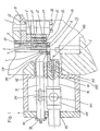
- the forming machine shown includes a shearing device a machine body 5 on which a pressure plate 53 an anvil 51 is attached.
- a first forming station 9 is indicated.
- a shaving and loading cassette 6 arranged, which can be detached in various ways Anvil 51 or can be attached to the machine body 5, for example by means of screws or hydraulic train or Print elements.
- the shear and load cassette 6 has a bar knife 2 in the form of a semi-cylindrical Half-knife attached to a bar knife carrier 21 is.
- an adjusting wedge 22 is arranged for Longitudinal displacement of the bar knife 2 for setting the Shear gap between the bar knife 2 and one in front placed section knife 1 is used.
- a charging pin 61 is arranged, which by means of a a compression nut 63 attaching compression nut 63 against one Charging control rod 8 is pressed.
- a guide tube 7 through which the bar into the bar knife 2 and the section knife 1 can be advanced, at most until they strikes a rod stop 52, which on the machine body 5 is attached.
- the section knife 1 is designed as a closed circular knife, attached in a section knife holder 11 which is removably attached to a cutter head 113.
- the section knife 1, the section knife holder 11 and the Cutter head 113 are part of a cutter head cartridge 110 which releasably on a by means of a fastening screw 122 slidable shear carriage 12 is attached, with which the section knife 1 is moved back and forth by a position in front of the bar knife 2 to a position in front of the charging pin 61 and back again.
- the drive of the shear carriage 12 explained below is on this a sliding block bearing 123 with a shear drive lever hole 121 provided.
- the bar to be sheared is on the one hand in section knife 1 and on the other hand between the bar knife 2 and an opposite centering and clamping piece 3 held in the clamped position.
- the centering and Clamping piece 3 lies on a centering and clamping piece pressure plate 314 on a centering and clamping slide head 313 of a centering and clamping slide 31 attached is.
- For the centering drive Clamping carriage 31 is a control lever hole on this 311 provided.
- On the centering and clamping slide head 313 opposite end of the centering and clamping slide 31 is attached a stroke limiting plate 32, the mode of operation is also explained below.
- the shear slide 12 and the centering and clamping slide 31 and the associated drives are in one on the machine body 5 anchored box 4 arranged, the Shear carriage 12 in bearing bushes 43, 44 and the centering Clamping slide 31 in bearing bushes 41, 42 in the box wall are slidably mounted.
- the centering and clamping piece 3 is initially at the beginning of Pushing briefly against the bar to be sheared into the centering position guided to center them without jamming.
- the rod can then optimally into the closed section knife 1 are introduced. Then it will Centering and clamping piece 3 during further insertion the rod to be sheared into the opening of the section knife 1 from the bar to be sheared to the release position moved away, i.e. vented to unnecessary friction and disadvantageous Prevent heat loss from the bar and prevent it from falling out of any scale.
- the rod is advanced in the desired dimension, the centering Clamp 3 on the rod to be sheared in the clamped position pressed to this during the actual shearing to pinch.
- the shearing is done by a quick Shift of the section knife 1 from the position in front the bar knife 2 to the position in front of the charging pin 61.
- the sheared section is finally removed by means of the Charging control rod 8 from the charging pin 61 pushed forward the section knife 1 pushed into a cross transport pliers 90 and transported from this to the first forming station 9.
- the transverse transport tongs 90 are located in FIG. 1 at the first forming station 9.
- the drive of the shear carriage 12 via a shear drive lever 13, which in the shear drive lever hole 121 protrudes in the sliding block bearing 123 and there surrounded by a close-fitting sliding block 131 is which can rotate in the sliding block bearing 123.
- the Shear drive lever 13 is via an overload protection device 19 with a predetermined breaking point 191 fixed with a double roller lever 14 connected, the shear drive lever 13 and the Double roller lever 14 rotatable about a common axis of rotation 132 are.
- On the double roller lever 14 is on the one hand an axis of rotation 151 rotatable shear roller 15 and on the other a counter roller 16 rotatable about an axis of rotation 161 is arranged.
- the shear roller 15 is due to one only indicated here Shear curve 17 on, while the counter roller 16 on one here only indicated counter curve 18 is present, the two Curves are rotated by means of a control shaft 170.
- Shear curve 17 and the counter curve 18 can the desired back and forth movement of the Shear carriage 12 and thus the section knife 1 reached become.
- the overload protection device 19 breaks at the predetermined breaking point 191 and the shear drive lever 13 is from the double roller lever 14 decoupled.
- the first one is in front of the first forming station 9
- the section knife holder 11 carrying the section knife 1 and thus the section knife 1 itself is in the x and y directions by means of a fitting plate 116 or 114 and additionally a correction plate 117 or 115 in the cutter head 113 can be precisely positioned in the cutter head cassette 110.
- the fitting plates 114, 116 are on the cutter head 113 permanently installed and then no longer removed during correction plates 115, 117 with a certain thickness on the section knife holder 11 or on the fitting plates 114, 116 are interchangeably attached.
- set screws 118, 119 becomes the section knife holder 11 with the correction plates 115, 117 pressed against the fitting plates 114, 116 and so fixed on the cutter head 113.
- the Section knife holder 11 via two fastening bridges 111 stable with the cutter head using fastening screws 112 113 connected so that those occurring during shear high forces for no loosening of the section knife holder 11 to lead.
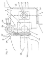
- the centering and clamping slide 31 is by means of a a clamping spring housing 341 arranged clamping spring 34, the on an annular shoulder 312 of the centering and clamping slide 31 starts, biased against the bar knife 2. is itself between the centering and clamping piece 3 and the Bar knife 2 no bar, limits one with fastening screws 322 on the centering and clamping slide 31 attached stroke limiting plate 32 moving the Centering and clamping slide 31 in the direction of the bar knife 2 by pulling on an annular stroke limit stop 324 on box 4. This prevents that the centering and clamping piece 3 and the bar knife 2 touch.
- the centering and clamping slide 31 is driven via a control arm protruding into the control lever hole 311 361 of a control lever 36 which is rotatable about an axis of rotation 363 is.
- a control roller 37 On a roller arm 362 of the control lever 36 a control roller 37 rotatable about an axis of rotation 371.
- the Control roller 37 bears against a control cam 38, which means a control shaft 381 is rotated.
- the movement of the control arm 361 is via a hinge pin 35 transferred to a compression spring housing 331, which an adapter 323 against one in the stroke limiting plate 32 arranged adjusting screw 321 presses.
- a compression spring housing 331 which an adapter 323 against one in the stroke limiting plate 32 arranged adjusting screw 321 presses.
- One in Compression spring housing 331 arranged on the intermediate piece Practice 323 supporting compression spring 33 and clamping spring 34 a torque from the control lever 36 so that the Control roller 37 permanently pressed against the cam 38 becomes.
- the control cam 38 thus acts via the control roller 37, the control lever 36, the pivot pin 35, the compression spring housing 331, the intermediate piece 323, the adjusting screw 321 and the stroke limiting plate 32 on the centering and Clamping slide 31 in opposite to the clamping spring 34 Direction.
- Appropriate training of the control curve 33 the desired back and forth movement of the centering and clamping slide 31 and thus the centering and Clamping piece 3 can be reached.
- the adjusting screw 321 which is by means of a fixing nut 325 can be blocked, the distance between the centering and Clamping piece 3 can be adjusted by the bar knife 2 that the centering and clamping piece 3 and the bar knife 2 together delimit a circular cylindrical opening.
- Such an adjustment can often be necessary because, as explained below, the position of the bar knife 2 varies in the x direction.
- centering and clamping piece 3 by means of a fastening screw 391 on a centering Clamping piece carrier 39 is attached.
- the centering and Clamping piece carrier 39 can be rotated via a pivot pin 392 connected to the bar knife carrier 21 on which the bar knife 2 is attached.
- a torsion spring 393 on a spring system 394 on the centering and clamping piece carrier 39 and on a spring system 23 on the bar knife carrier 21 starts is the centering and clamping piece carrier 39 biased with respect to the bar knife carrier 21, that the centering and clamping piece 3 from the bar knife 2 away against that attached to the centering and clamping slide 31 Centering and clamping piece pressure plate 314 pressed becomes.
- the lifting, centering and clamping movements of the Zencrier and clamping piece 3 can thus be introduced non-positively become.
- the removable shaving and loading cassette 6 with the bar knife holder 21 is in the x and y direction by means of one Fitting plate 64 or 66 and additionally one correction plate each 65 or 67 can be precisely positioned on the anvil 51.
- the Fitting plates 64, 66 are firmly mounted on the anvil 51 and thereafter no longer removed while correction plates 65, 67 with a certain thickness on the bar knife carrier 21 or are interchangeably attached to the fitting plates 64, 66.
- the thickness of the fitting plates 64, 66 can be determined.
- the x and y position of the bar knife 2 simply have to be one or both reference correction plates 65, 67 by correction plates 65, 67 corresponding thickness are replaced, the a set of correction plates with e.g. in ⁇ 1/10, 1/2 or 1 mm steps differing thicknesses are taken could.
- a Set screw 396 to limit the opening angle between the centering and clamping piece carrier 39 and the bar knife carrier 21 attached by means of a fixing nut 397 can be blocked.
Landscapes
- Engineering & Computer Science (AREA)
- Mechanical Engineering (AREA)
- Accessories And Tools For Shearing Machines (AREA)
- Shearing Machines (AREA)
- Details Of Cutting Devices (AREA)
- Forging (AREA)
- Processing And Handling Of Plastics And Other Materials For Molding In General (AREA)
- Crushing And Pulverization Processes (AREA)
- Perforating, Stamping-Out Or Severing By Means Other Than Cutting (AREA)
- Processing Of Stones Or Stones Resemblance Materials (AREA)
Description
- Fig. 1 -
- eine teilweise geschnitte Ansicht von oben wesentlicher Teile einer an einer Umformmaschine angeordneten Schervorrichtung;
- Fig. 2 -
- eine teilweise geschnittene Seitenansicht der Umformmaschine mit Schervorrichtung von Fig. 1, bei der das Abschnittmesser und der Scherschlitten sichtbar sind;
- Fig. 3 -
- eine Detailansicht der Anordnung des Abschnittmessers;
- Fig. 4 -
- eine teilweise geschnittene Seitenansicht der Umformmaschine mit Schervorrichtung von Fig. 1, bei der das Stangenmesser, das Zentrier- und Klemmstück und der Zentrier- und Klemmschlitten sichtbar sind; und
- Fig. 5 -
- eine Detailansicht der Anordnung des Stangenmessers und des Zentrier- und Klemmstücks.
- Anstatt die Einpassplatten 114, 116 am Messerkopf 113 und die Korrekturplatten 115, 117 am Abschnittmesserhalter 11 oder an den Einpassplatten 114, 116 zu montieren, könnten die Einpassplatten 114, 116 auch am Abschnittmesserhalter 11 und die Korrekturplatten 115, 117 am Messerkopf 113 oder an den Einpassplatten 114, 116 befestigt werden.
- Anstatt die Einpassplatten 64, 66 am Amboss 51 und die Korrekturplatten 65, 67 am Stangenmesserträger 21 oder an den Einpassplatten 64, 66 zu montieren, könnten die Einpassplatten 64, 66 auch am Stangenmesserträger 21 und die Korrekturplatten 65, 67 am Amboss 51 oder an den Einpassplatten 64, 66 befestigt werden.
- Die Scher- und Ladekassette 6 kann über die in x- und y-Richtung angeordneten Einpassplatten 64, 66 und Korrekturplatten 65, 67 auch auf verschiedene Arten an einem L-förmigen Kassettenträger lösbar befestigt sein. Der Kassettenträger mit der Scher- und Ladekassette 6 kann ebenfalls auf verschiedene Arten lösbar am Amboss 51 oder am Maschinenkörper 5 befestigt sein, beispielsweise mittels Schrauben oder hydraulischen Zug- oder Druckelementen.
- Die Verbindung zwischen Zentrier- und Klemmstückdruckplatte 314 und Zentrier- und Klemmstück 3 kann auch formschlüssig ausgebildet werden. Die Vorspannung des Zentrier- und Klemmstückträgers 3 bezüglich des Stangenmesserträgers 21 würde dann nicht mehr benötigt.
- Anstatt den Abstand des Zentrier- und Klemmstücks 3 vom Stangenmesser 2 mittels der Verstellschraube 321 einzustellen, kann dies auch durch eine motorisch angetriebene Gewindespindel geschehen.
- Die Messerkopfkassette 110 kann anstatt mittels der Befestigungsschraube 122 auch auf eine andere Weise lösbar am Scherschlitten 12 befestigt werden, beispielsweise mittels hydraulischen Zug- oder Druckelementen.
Claims (11)
- Umformmaschine mit einer Schervorrichtung, die ein geschlitztes Rundmesser, bestehend aus einem als Halbmesser ausgebildeten ortsfesten Stangenmesser (2) und einem dazu bewegbaren Zentrier- und Klemmstück (3), sowie ein mit dem geschlitzten Rundmesser zusammenwirkendes und dazu verschiebbares Abschnittmesser (1) aufweist, das als geschlossenes Rundmesser ausgebildet ist, dadurch gekennzeichnet, dass sie Steuermittel (38) aufweist, die derart ausgestaltet sind, dass durch sie das Zentrier- und Klemmstück (3) zwischen einer Zentrierstellung, in der es im Betrieb eine zu scherende Stange ohne zu klemmen zentriert, einer Lüftstellung, in der es ganz von der zu scherenden Stange weggefahren ist, und einer Klemmstellung, in der es die zu scherende Stange klemmt, gesteuert bewegt wird.
- Umformmaschine nach Anspruch 1, dadurch gekennzeichnet, dass das Abschnittmesser (1) in einem Abschnittmesserhalter (11) angeordnet ist, der mittels je einer Einpassplatte (114, 116) pro Richtung und vorzugsweise zusätzlich je einer Korrekturplatte (115, 117) pro Richtung bezüglich einer geforderten Lage einer zu scherenden Stange in zwei Richtungen senkrecht zu der zu scherenden Stange genau positionierbar ist.
- Umformmaschine nach Anspruch 2, dadurch gekennzeichnet, dass der Abschnittmesserhalter (11) an einem Messerkopf (113) abnehmbar befestigt ist, welcher an einem verschiebbaren Scherschlitten (12) angebracht ist.
- Umformmaschine nach Anspruch 3, dadurch gekennzeichnet, dass das Abschnittmesser (1), der Abschnittmesserhalter (11) und der Messerkopf (113) Teil einer abnehmbaren Messerkopfkassette (110) sind.
- Umformmaschine nach einem der Ansprüche 1 bis 4, dadurch gekennzeichnet, dass die Steuermittel eine Steuerkurve (38) umfassen, die so geformt ist, dass das Zentrierund Klemmstück (3) zunächst zu Beginn des Einschiebens kurz gegen die zu scherende Stange in die Zentrierstellung geführt wird, um diese ohne zu klemmen zu zentrieren, anschliessend während des weiteren Einschiebens der zu scherenden Stange in die Öffnung des Abschnittmessers (1) von der zu scherenden Stange in die Lüftstellung weggefahren wird, dann ganz an die zu scherende Stange in die Klemmstellung geführt wird, um diese während des eigentlichen Scherens zu klemmen, und schliesslich wieder von der zu scherenden Stange weggefahren wird.
- Umformmaschine nach Anspruch 5, dadurch gekennzeichnet, dass das Zentrier- und Klemmstück (3) mittels. eines Zentrier- und Klemmschlittens (31) bewegbar ist, der von der Steuerkurve (38) gesteuert ist.
- Umformmaschine nach einem der Ansprüche 1 bis 6, dadurch gekennzeichnet, dass das Zentrier- und Klemmstück (3) an einem Zentrier- und Klemmstuckträger (39) angebracht ist, der bewegbar, vorzugsweise drehbar, mit einem Stangenmesserträger (21) verbunden ist, an dem das Stangenmesser (2) angebracht ist.
- Umformmaschine nach Anspruch 7, dadurch gekennzeichnet, dass der Zentrier- und Klemmstückträger (39) derart vorgespannt ist, dass das Zentrier- und Klemmstück (3) vom Stangenmesser (2) weg gegen eine am Zentrier- und Klemmschlitten (31) angebrachte Zentrier- und Klemmstückdruckplatte (314) gedrückt wird.
- Umformmaschine nach einem der Ansprüche 1 bis 8, dadurch gekennzeichnet, dass das durch das Stangenmesser (2) und das Zentrier- und Klemmstück (3) gebildete geschlitzte Rundmesser mittels je einer Einpassplatte (64, 66) pro Richtung und vorzugsweise zusätzlich je einer Korrekturplatte (65, 67) pro Richtung bezüglich einer geforderten Lage einer zu scherenden Stange in zwei Richtungen senkrecht zu der zu scherenden Stange genau positionierbar ist.
- Umformmaschine nach einem der Ansprüche 1 bis 9, dadurch gekennzeichnet, dass das Stangenmesser (2), das Zentrier- und Klemmstück (3) und gegebenenfalls der Zentrier- und Klemmstückträger (39) und der Stangenmesserträger (21) in einer abnehmbaren Scher- und Ladekassette (6) angeordnet sind.
- Umformmaschine nach einem der Ansprüche 1 bis 10, dadurch gekennzeichnet, dass sie eine Warmumformmaschine ist.
Applications Claiming Priority (3)
| Application Number | Priority Date | Filing Date | Title |
|---|---|---|---|
| CH188499 | 1999-10-15 | ||
| CH188499 | 1999-10-15 | ||
| PCT/CH2000/000513 WO2001028711A1 (de) | 1999-10-15 | 2000-09-22 | Umformmaschine mit einer schervorrichtung |
Publications (2)
| Publication Number | Publication Date |
|---|---|
| EP1220726A1 EP1220726A1 (de) | 2002-07-10 |
| EP1220726B1 true EP1220726B1 (de) | 2003-07-16 |
Family
ID=4220855
Family Applications (1)
| Application Number | Title | Priority Date | Filing Date |
|---|---|---|---|
| EP00960267A Expired - Lifetime EP1220726B1 (de) | 1999-10-15 | 2000-09-22 | Umformmaschine mit einer schervorrichtung |
Country Status (14)
| Country | Link |
|---|---|
| US (1) | US6748785B1 (de) |
| EP (1) | EP1220726B1 (de) |
| JP (1) | JP3706067B2 (de) |
| KR (1) | KR100459976B1 (de) |
| CN (1) | CN1141195C (de) |
| AT (1) | ATE245063T1 (de) |
| AU (1) | AU7264800A (de) |
| CZ (1) | CZ2002906A3 (de) |
| DE (1) | DE50002928D1 (de) |
| EA (1) | EA003356B1 (de) |
| ES (1) | ES2203509T3 (de) |
| TW (1) | TW480202B (de) |
| UA (1) | UA71999C2 (de) |
| WO (1) | WO2001028711A1 (de) |
Families Citing this family (6)
| Publication number | Priority date | Publication date | Assignee | Title |
|---|---|---|---|---|
| US20050246885A1 (en) * | 2004-05-04 | 2005-11-10 | Mahan Jonathan D F | Bed knife and method of forming |
| TWI294800B (en) | 2005-02-17 | 2008-03-21 | Hatebur Umformmaschinen Ag | Forming machine having a shearing device for shearing a bar |
| CN100381226C (zh) * | 2005-03-17 | 2008-04-16 | 运通工业股份有限公司 | 具隐藏式复位装置的部件成型机的切料装置 |
| CN100395053C (zh) * | 2005-03-17 | 2008-06-18 | 运通工业股份有限公司 | 具有位置调整功能的部件成型机的切料装置 |
| CH701324A1 (de) * | 2009-06-16 | 2010-12-31 | Hatebur Umformmaschinen Ag | Schervorrichtung zum Scheren von Stangenmaterial und Umformmaschine mit einer Schervorrichtung zum Scheren von Stangenmaterial. |
| EP3532229B1 (de) * | 2016-10-28 | 2026-01-14 | Lukas Hydraulik GmbH | Schermesser mit einem schneidgerät |
Family Cites Families (13)
| Publication number | Priority date | Publication date | Assignee | Title |
|---|---|---|---|---|
| US2215927A (en) * | 1938-10-08 | 1940-09-24 | Nat Tube Co | Self-centering chuck |
| US2601716A (en) * | 1949-11-09 | 1952-07-01 | Ray J Laningham | Precision turning, threading, and centering lathe attachment |
| US3182538A (en) * | 1961-08-31 | 1965-05-11 | Continental Machines | Machine for cutting lengths of stock into pieces |
| US3204504A (en) * | 1962-07-12 | 1965-09-07 | Textron Inc | Positive grip cut-off |
| DE1752917A1 (de) * | 1967-08-21 | 1971-04-08 | Vyzk Ustav Tvarzecich Stroju A | Einrichtung zum Schneiden von Profilmaterial,insbesondere runden Querschnittes |
| SU483203A1 (ru) * | 1973-10-02 | 1975-09-05 | Экспериментальный Научно-Исследовательский Институт Кузнечно-Прессовго Машиностроения | Устройство дл резки коротких заготовок |
| DE2604418C2 (de) | 1976-02-05 | 1982-06-03 | Friedrich Wilhelm Dipl.-Ing. 5600 Wuppertal Elhaus | Barren-Warmschere |
| SU703255A1 (ru) * | 1977-06-21 | 1979-12-15 | Воронжский Ордена Ленина Завод Тяжелых Механических Прессов | Устройство дл резки пруткого материала |
| SU749578A1 (ru) * | 1977-10-03 | 1980-07-23 | Предприятие П/Я А-1575 | Штамп дл резки труб |
| JPS6360038A (ja) * | 1986-08-28 | 1988-03-16 | Sumitomo Metal Ind Ltd | 熱間鍛造装置の操業方法 |
| US4872384A (en) * | 1988-01-29 | 1989-10-10 | Borzym John J | Tube cutting apparatus |
| DE3841584C1 (de) * | 1988-12-09 | 1990-02-01 | Elhaus Industrieanlagen Gmbh, 7703 Rielasingen-Worblingen, De | |
| JP2741351B2 (ja) * | 1994-11-09 | 1998-04-15 | 旭サナック株式会社 | 圧造機における素材切断装置 |
-
2000
- 2000-09-22 AU AU72648/00A patent/AU7264800A/en not_active Abandoned
- 2000-09-22 ES ES00960267T patent/ES2203509T3/es not_active Expired - Lifetime
- 2000-09-22 EP EP00960267A patent/EP1220726B1/de not_active Expired - Lifetime
- 2000-09-22 WO PCT/CH2000/000513 patent/WO2001028711A1/de not_active Ceased
- 2000-09-22 CN CNB008141622A patent/CN1141195C/zh not_active Expired - Fee Related
- 2000-09-22 DE DE50002928T patent/DE50002928D1/de not_active Expired - Fee Related
- 2000-09-22 US US10/110,433 patent/US6748785B1/en not_active Expired - Fee Related
- 2000-09-22 CZ CZ2002906A patent/CZ2002906A3/cs unknown
- 2000-09-22 UA UA2002043070A patent/UA71999C2/uk unknown
- 2000-09-22 AT AT00960267T patent/ATE245063T1/de not_active IP Right Cessation
- 2000-09-22 EA EA200200449A patent/EA003356B1/ru not_active IP Right Cessation
- 2000-09-22 KR KR10-2002-7004416A patent/KR100459976B1/ko not_active Expired - Fee Related
- 2000-09-22 JP JP2001531532A patent/JP3706067B2/ja not_active Expired - Fee Related
- 2000-10-13 TW TW89121496A patent/TW480202B/zh not_active IP Right Cessation
Also Published As
| Publication number | Publication date |
|---|---|
| WO2001028711A1 (de) | 2001-04-26 |
| KR20020043615A (ko) | 2002-06-10 |
| CZ2002906A3 (cs) | 2003-04-16 |
| ES2203509T3 (es) | 2004-04-16 |
| JP3706067B2 (ja) | 2005-10-12 |
| TW480202B (en) | 2002-03-21 |
| KR100459976B1 (ko) | 2004-12-03 |
| EA200200449A1 (ru) | 2002-10-31 |
| DE50002928D1 (de) | 2003-08-21 |
| EP1220726A1 (de) | 2002-07-10 |
| UA71999C2 (en) | 2005-01-17 |
| ATE245063T1 (de) | 2003-08-15 |
| EA003356B1 (ru) | 2003-04-24 |
| JP2003512175A (ja) | 2003-04-02 |
| CN1141195C (zh) | 2004-03-10 |
| AU7264800A (en) | 2001-04-30 |
| CN1378488A (zh) | 2002-11-06 |
| US6748785B1 (en) | 2004-06-15 |
Similar Documents
| Publication | Publication Date | Title |
|---|---|---|
| DE4211276C2 (de) | Haltevorrichtung zum Halten, Führen und Freigeben eines Fügeteils, wie z.B. einer Mutter | |
| DE2921194C2 (de) | Vorrichtung zum Vorschub und zur Bearbeitung stangenförmigen Werkstückmaterials bei einer Trennmaschine | |
| DE2548771B2 (de) | Vorschub- und Spanneinrichtung für eine Trennmaschine | |
| EP1306149B1 (de) | Schälgerät mit schwenkbarem Schälkopf | |
| DE69619546T2 (de) | Verbesserungen an oder im zusammenhang mit dem bohrschleifen | |
| EP1848556B1 (de) | Umformmaschine mit einer schervorrichtung zum scheren einer stange | |
| DE69313639T2 (de) | Verstellbarer drahtschneid- und entmantelungsapparat | |
| DE3141248C2 (de) | Einrichtung zum Zuführen von Schrauben für einen motorbetriebenen Schraubenzieher | |
| WO2001028711A1 (de) | Umformmaschine mit einer schervorrichtung | |
| EP3439806B1 (de) | Biegemaschine | |
| EP2000117B1 (de) | Vorrichtung zum Präparieren von Gewebescheiben, insbesondere Knorpelscheiben | |
| DE1552657C3 (de) | Vorrichtung zur radialen Fuhrung des Stanzstempels von Aushaumaschinen | |
| EP1381124B1 (de) | Crimppresse mit Kontaktzuführung | |
| EP3505355A1 (de) | Abschneidevorrichtung fuer endlosetiketten | |
| EP0672493B1 (de) | Rohrabstechgerät für Kunststoffrohre | |
| DE1069993B (de) | Querfordervorrichtung für eine bolzen-oder mutternpresse | |
| DE1552612C3 (de) | Schneidemaschine für Stabmateria] | |
| DE1502774A1 (de) | Anschlagvorrichtung bei einer Schere,insbesondere Blechschere | |
| DE3509603A1 (de) | Warmschere | |
| EP0597247A2 (de) | Zuführvorrichtung für elektrische Kontaktelemente in Crimpwerkzeugen einer Crimppresse | |
| EP1042850B1 (de) | Abisoliervorrichtung | |
| DE69008347T2 (de) | Rillenwalzvorrichtung. | |
| DE2910633A1 (de) | Vorrichtung zum biegen, sicken und ablaengen der anschlussdraehte von elektrischen bauelementen | |
| DE102007035212B4 (de) | Locher | |
| DE606884C (de) |
Legal Events
| Date | Code | Title | Description |
|---|---|---|---|
| PUAI | Public reference made under article 153(3) epc to a published international application that has entered the european phase |
Free format text: ORIGINAL CODE: 0009012 |
|
| 17P | Request for examination filed |
Effective date: 20020311 |
|
| AK | Designated contracting states |
Kind code of ref document: A1 Designated state(s): AT BE CH CY DE DK ES FI FR GB GR IE IT LI LU MC NL |
|
| AX | Request for extension of the european patent |
Free format text: AL;LT;LV;MK;RO;SI |
|
| 17Q | First examination report despatched |
Effective date: 20020813 |
|
| GRAH | Despatch of communication of intention to grant a patent |
Free format text: ORIGINAL CODE: EPIDOS IGRA |
|
| GRAH | Despatch of communication of intention to grant a patent |
Free format text: ORIGINAL CODE: EPIDOS IGRA |
|
| GRAA | (expected) grant |
Free format text: ORIGINAL CODE: 0009210 |
|
| AK | Designated contracting states |
Designated state(s): AT BE CH CY DE DK ES FI FR GB GR IE IT LI LU MC NL PT SE |
|
| PG25 | Lapsed in a contracting state [announced via postgrant information from national office to epo] |
Ref country code: FI Free format text: LAPSE BECAUSE OF FAILURE TO SUBMIT A TRANSLATION OF THE DESCRIPTION OR TO PAY THE FEE WITHIN THE PRESCRIBED TIME-LIMIT Effective date: 20030716 Ref country code: IE Free format text: LAPSE BECAUSE OF FAILURE TO SUBMIT A TRANSLATION OF THE DESCRIPTION OR TO PAY THE FEE WITHIN THE PRESCRIBED TIME-LIMIT Effective date: 20030716 |
|
| REG | Reference to a national code |
Ref country code: GB Ref legal event code: FG4D Free format text: NOT ENGLISH |
|
| REG | Reference to a national code |
Ref country code: CH Ref legal event code: EP |
|
| GBT | Gb: translation of ep patent filed (gb section 77(6)(a)/1977) |
Effective date: 20030716 |
|
| REG | Reference to a national code |
Ref country code: CH Ref legal event code: NV Representative=s name: A. BRAUN, BRAUN, HERITIER, ESCHMANN AG PATENTANWAE |
|
| REG | Reference to a national code |
Ref country code: IE Ref legal event code: FG4D Free format text: GERMAN |
|
| REF | Corresponds to: |
Ref document number: 50002928 Country of ref document: DE Date of ref document: 20030821 Kind code of ref document: P |
|
| PG25 | Lapsed in a contracting state [announced via postgrant information from national office to epo] |
Ref country code: LU Free format text: LAPSE BECAUSE OF NON-PAYMENT OF DUE FEES Effective date: 20030922 Ref country code: CY Free format text: LAPSE BECAUSE OF FAILURE TO SUBMIT A TRANSLATION OF THE DESCRIPTION OR TO PAY THE FEE WITHIN THE PRESCRIBED TIME-LIMIT Effective date: 20030922 Ref country code: AT Free format text: LAPSE BECAUSE OF NON-PAYMENT OF DUE FEES Effective date: 20030922 |
|
| PG25 | Lapsed in a contracting state [announced via postgrant information from national office to epo] |
Ref country code: MC Free format text: LAPSE BECAUSE OF NON-PAYMENT OF DUE FEES Effective date: 20030930 |
|
| PG25 | Lapsed in a contracting state [announced via postgrant information from national office to epo] |
Ref country code: DK Free format text: LAPSE BECAUSE OF FAILURE TO SUBMIT A TRANSLATION OF THE DESCRIPTION OR TO PAY THE FEE WITHIN THE PRESCRIBED TIME-LIMIT Effective date: 20031016 Ref country code: SE Free format text: LAPSE BECAUSE OF FAILURE TO SUBMIT A TRANSLATION OF THE DESCRIPTION OR TO PAY THE FEE WITHIN THE PRESCRIBED TIME-LIMIT Effective date: 20031016 Ref country code: GR Free format text: LAPSE BECAUSE OF FAILURE TO SUBMIT A TRANSLATION OF THE DESCRIPTION OR TO PAY THE FEE WITHIN THE PRESCRIBED TIME-LIMIT Effective date: 20031016 |
|
| LTIE | Lt: invalidation of european patent or patent extension |
Effective date: 20030716 |
|
| ET | Fr: translation filed | ||
| REG | Reference to a national code |
Ref country code: IE Ref legal event code: FD4D |
|
| REG | Reference to a national code |
Ref country code: ES Ref legal event code: FG2A Ref document number: 2203509 Country of ref document: ES Kind code of ref document: T3 |
|
| PLBE | No opposition filed within time limit |
Free format text: ORIGINAL CODE: 0009261 |
|
| STAA | Information on the status of an ep patent application or granted ep patent |
Free format text: STATUS: NO OPPOSITION FILED WITHIN TIME LIMIT |
|
| 26N | No opposition filed |
Effective date: 20040419 |
|
| PG25 | Lapsed in a contracting state [announced via postgrant information from national office to epo] |
Ref country code: PT Free format text: LAPSE BECAUSE OF NON-PAYMENT OF DUE FEES Effective date: 20031216 |
|
| REG | Reference to a national code |
Ref country code: CH Ref legal event code: PFA Owner name: HATEBUR UMFORMMASCHINEN AG Free format text: HATEBUR UMFORMMASCHINEN AG#GENERAL GUISAN-STRASSE 21#CH-4153 REINACH (CH) -TRANSFER TO- HATEBUR UMFORMMASCHINEN AG#GENERAL GUISAN-STRASSE 21#CH-4153 REINACH (CH) |
|
| PGFP | Annual fee paid to national office [announced via postgrant information from national office to epo] |
Ref country code: CH Payment date: 20080924 Year of fee payment: 9 Ref country code: ES Payment date: 20080917 Year of fee payment: 9 |
|
| PGFP | Annual fee paid to national office [announced via postgrant information from national office to epo] |
Ref country code: FR Payment date: 20080916 Year of fee payment: 9 Ref country code: IT Payment date: 20080909 Year of fee payment: 9 Ref country code: NL Payment date: 20080930 Year of fee payment: 9 |
|
| PGFP | Annual fee paid to national office [announced via postgrant information from national office to epo] |
Ref country code: GB Payment date: 20080912 Year of fee payment: 9 |
|
| PGFP | Annual fee paid to national office [announced via postgrant information from national office to epo] |
Ref country code: DE Payment date: 20081128 Year of fee payment: 9 |
|
| PGFP | Annual fee paid to national office [announced via postgrant information from national office to epo] |
Ref country code: BE Payment date: 20080929 Year of fee payment: 9 |
|
| BERE | Be: lapsed |
Owner name: *HATEBUR UMFORMMASCHINEN A.G. Effective date: 20090930 |
|
| REG | Reference to a national code |
Ref country code: NL Ref legal event code: V1 Effective date: 20100401 |
|
| REG | Reference to a national code |
Ref country code: CH Ref legal event code: PL |
|
| GBPC | Gb: european patent ceased through non-payment of renewal fee |
Effective date: 20090922 |
|
| REG | Reference to a national code |
Ref country code: FR Ref legal event code: ST Effective date: 20100531 |
|
| PG25 | Lapsed in a contracting state [announced via postgrant information from national office to epo] |
Ref country code: FR Free format text: LAPSE BECAUSE OF NON-PAYMENT OF DUE FEES Effective date: 20090930 Ref country code: NL Free format text: LAPSE BECAUSE OF NON-PAYMENT OF DUE FEES Effective date: 20100401 Ref country code: DE Free format text: LAPSE BECAUSE OF NON-PAYMENT OF DUE FEES Effective date: 20100401 |
|
| PG25 | Lapsed in a contracting state [announced via postgrant information from national office to epo] |
Ref country code: BE Free format text: LAPSE BECAUSE OF NON-PAYMENT OF DUE FEES Effective date: 20090930 |
|
| PG25 | Lapsed in a contracting state [announced via postgrant information from national office to epo] |
Ref country code: LI Free format text: LAPSE BECAUSE OF NON-PAYMENT OF DUE FEES Effective date: 20090930 Ref country code: CH Free format text: LAPSE BECAUSE OF NON-PAYMENT OF DUE FEES Effective date: 20090930 |
|
| PG25 | Lapsed in a contracting state [announced via postgrant information from national office to epo] |
Ref country code: GB Free format text: LAPSE BECAUSE OF NON-PAYMENT OF DUE FEES Effective date: 20090922 |
|
| PG25 | Lapsed in a contracting state [announced via postgrant information from national office to epo] |
Ref country code: IT Free format text: LAPSE BECAUSE OF NON-PAYMENT OF DUE FEES Effective date: 20090922 |
|
| REG | Reference to a national code |
Ref country code: ES Ref legal event code: FD2A Effective date: 20110714 |
|
| PG25 | Lapsed in a contracting state [announced via postgrant information from national office to epo] |
Ref country code: ES Free format text: LAPSE BECAUSE OF NON-PAYMENT OF DUE FEES Effective date: 20110704 |
|
| PG25 | Lapsed in a contracting state [announced via postgrant information from national office to epo] |
Ref country code: ES Free format text: LAPSE BECAUSE OF NON-PAYMENT OF DUE FEES Effective date: 20090923 |