EP1220005B1 - Microscope - Google Patents
Microscope Download PDFInfo
- Publication number
- EP1220005B1 EP1220005B1 EP01127889A EP01127889A EP1220005B1 EP 1220005 B1 EP1220005 B1 EP 1220005B1 EP 01127889 A EP01127889 A EP 01127889A EP 01127889 A EP01127889 A EP 01127889A EP 1220005 B1 EP1220005 B1 EP 1220005B1
- Authority
- EP
- European Patent Office
- Prior art keywords
- tube lens
- reflector
- spectral region
- microscope according
- duv
- Prior art date
- Legal status (The legal status is an assumption and is not a legal conclusion. Google has not performed a legal analysis and makes no representation as to the accuracy of the status listed.)
- Expired - Lifetime
Links
- 230000003595 spectral effect Effects 0.000 claims description 36
- 230000003287 optical effect Effects 0.000 claims description 17
- 238000005286 illumination Methods 0.000 claims description 13
- 238000003384 imaging method Methods 0.000 claims 2
- 230000000717 retained effect Effects 0.000 claims 1
- 230000008878 coupling Effects 0.000 description 7
- 238000010168 coupling process Methods 0.000 description 7
- 238000005859 coupling reaction Methods 0.000 description 7
- 238000000034 method Methods 0.000 description 7
- 230000004075 alteration Effects 0.000 description 4
- 238000013507 mapping Methods 0.000 description 2
- 239000000463 material Substances 0.000 description 2
- 239000004065 semiconductor Substances 0.000 description 2
- 230000015572 biosynthetic process Effects 0.000 description 1
- 210000003746 feather Anatomy 0.000 description 1
- 238000011835 investigation Methods 0.000 description 1
- 230000007257 malfunction Effects 0.000 description 1
- 238000001000 micrograph Methods 0.000 description 1
- 238000000386 microscopy Methods 0.000 description 1
- 238000001228 spectrum Methods 0.000 description 1
- 235000012431 wafers Nutrition 0.000 description 1
Images


Classifications
-
- G—PHYSICS
- G02—OPTICS
- G02B—OPTICAL ELEMENTS, SYSTEMS OR APPARATUS
- G02B21/00—Microscopes
- G02B21/18—Arrangements with more than one light path, e.g. for comparing two specimens
Definitions
- the invention relates to a microscope with a possibility for switching the Illumination between the ultraviolet spectral range and the visible VIS spectral range.
- a microscope of the type mentioned initially describes EP 0 896 237.
- Sie has a reflector support with several optionally in the illumination beam path einbringbaren reflectors on the ultraviolet spectral range or the visible VIS spectral range.
- a switch of the illumination beam path to a selected spectral range takes place by a reflector associated with this spectral region in the Illumination beam path is introduced.
- the mapping always takes place in the visible spectral range.
- the microscope is done also the image in the ultraviolet spectral range, what a better Resolution causes.
- a lighting and picture of the sample in the far ultraviolet DUV spectral range is not specified.
- the resolution of a microscope depends essentially on the wavelength of the illumination light used.
- Conventional microscopes are operated with light in the visible wavelength range (hereinafter abbreviated as VIS spectral range - for English " vis ible” - called).
- VIS spectral range - for English " vis ible” - called.
- DUV Spektral Scheme- for English " d eep u ltra v iolet” - called
- the microscope image is visualized in DUV operation with a TV camera sensitive to the DUV light.
- the materials in conventional optics, for the VIS spectral range are not permeable in the DUV spectral range. Therefore are in the DUV operation of the microscope optics built from special materials like prisms, beam splitters, tube lenses as well as lenses required, which are corrected for DUV wavelengths.
- the semiconductor industry preferably has a DUV microscope Switching options between VIS and DUV optics and the respective associated lighting on, in which also a switching between VIS and DUV lenses.
- both for work in the DUV spectral range as well as in the VIS spectral range are additionally adjustable reflectors and filters in the illumination beam path for various microscopy and contrasting methods (such as Brightfield, darkfield, interference-contrast and DUV methods) provided and arranged on a reflector support.
- the attitude can be done by hand or preferably by motor
- a tube lens need not only one certain lens, but in addition to a specific reflector or filters are assigned.
- a specific reflector or filters are assigned.
- the assignment of the motor adjustable reflectors (or filters) on the one hand and the corresponding Tubus lens on the other hand then done by software.
- Tubuslinsenwechslers or the Tubuslinse are on the one hand the consuming and space-intensive Use of a motor drive for Tubuslinsenwechsler and on the other hand the circumstance that a program malfunction or a program failure to incorrect assignment of reflector and tube lens when working in the UV light range can lead.
- the invention is based on the object, a microscope with a simple and secure switching option for optional Working in the far ultraviolet or visible spectral range.
- the inventive mechanical forced coupling of the movement of the reflector carrier with the Tubuslinsenwechsler can on its own Drive for the Tubuslinsenwechsler be waived.
- the mechanical coupling of the two modules designed so that, for example automatically the reflector for investigations in the DUV spectral range a DUV tube lens is assigned. This eliminates the need a separate and therefore error-prone software-related or similar assignment of the modules to each other.
- the forced coupling between reflector carrier and Tubuslinsenwechsler via at least one driving pin, which is defined as the reflector carrier Pen is formed in a corresponding receptacle of Tubuslinsenwechslers engages and this when adjusting the reflector carrier inevitably takes along.
- the Tubuslinsenwechsler is advantageously space-saving than rotatably mounted Disk formed whose angle of rotation for adjusting the Tubuslinsen can be limited in the optical axis by adjustable stops.
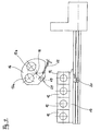
- FIG. 1 schematically shows the structure of a microscope, in this case a reflected-light microscope.
- the microscope shown consists essentially of two optical systems, an objective 1 and an eyepiece 2, which are interconnected by a tube 3, a lighting device 4 and a stage 5 for receiving a sample to be examined 6 and a stand 7 for holding the optical parts.
- microscope For observation, presentation and storage and editing is the illustrated microscope further with a camera 8 and a computer. 9 equipped with monitor 10.
- the illumination device 4 of this reflected-light microscope consists of a in a light source 4b arranged in a lamp housing 4a, the light of which is along the optical axis 11 of the illumination beam path via an illumination optical system 4c and 4d aperture is directed to a reflector 12 to from this to be deflected onto the arranged on the stage 5 sample 6.
- the reflector deflecting the light beam of the illumination beam path 12 is arranged on a trained as a linear slide reflector support 13, the multiple reflectors or filters 12 carries, depending on the selected Spectral range and contrast methods can be introduced into the optical axis.
- the reflector support 13 is motorized via a drive 14 drivable.
- a tube lens changer 16 is arranged above the reflector carrier 13, via which a corresponding tube lens 17 can be pivoted into the optical axis 15 as a function of the selected contrast method and thus of the selected reflector 12.
- the tube lens changer 16 is designed as a disk pivotable about a pivot point 18.
- a beam splitter 19 is further arranged.
- the assignment of a specific tube lens 17 to a specific contrast method and thus reflector 12 takes place in such a way that accordingly the selected spectral range (VIS or DUV) a matching lens is selected and this associated with the compensation system Tubus lens is assigned.
- the illustrated microscope designed so that when arranging the DUV reflector 12 by means of the reflector support 13 in the illumination beam path automatically the Tubuslinsenwechsler 16 is actuated so that a DUV tube lens 17 in the optical Arranged axis 15 of the viewing beam path and thus the matching Lens is assigned.
- the exact structure of the formed as a linear slide reflector support 13 and the tube lens carrier 16 is shown in the figures Fig. 2 to 5 .
- FIGS. 2, 3 and 4 show a reflector support 13 with three reflectors 12 arranged thereon, in the illustrated case the rightmost reflector 12 being a DUV reflector 12.
- the tube lens changer 16 is arranged, which according to FIGS. 2 to 4 is provided with two tube lenses 17, namely a DUV tube lens 17a for the DUV spectral range and a VIS tube lens 17b for the visible VIS lens. spectral range.
- a DUV tube lens 17a for the DUV spectral range
- VIS tube lens 17b for the visible VIS lens.
- VIS lenses can also be used with different VIS lenses as well as different DUV lenses also different DUV Tubuslinsen be provided (not shown here).
- the Tubuslinsenwechsler 16 is pivotable about the pivot point 18 between the end positions shown in Figures 2 and 3 , wherein the angle of rotation is limited in the end positions by stops 21.
- the stops 21 are formed adjustable.
- the Tubuslinsenwechsler 16 has a spring 22 which biases the Tubuslinsenwechsler in the end positions against the respective stop 21 to keep the respective tube lens 17 securely in the correct position in the optical axis 15.
- the mechanical positive coupling between the reflector support 13 on the one hand and the Tubuslinsenwechsler 16 on the other causing entrainment pin 20 is set at the level of the DUV reflector 12 on the reflector support 13.
- the driving pin 20 engages in a receptacle 23 formed in the tube lens changer 16.
- Each tube lens 17 may be formed as a lens system composed of a plurality of lenses.
- FIG. 5 shows an alternative embodiment of reflector support 13 and tube lens changer 16.
- the tube lens changer 16 is equipped with three tube lenses 17.
- the reflector support 13 has two drive pins 20 which can each enter into a corresponding receptacle 23 of the tube lens changer 16 in order to adjust the tube lens changer 16 to the tube lens 17 corresponding to the respective reflector 12.
Landscapes
- Physics & Mathematics (AREA)
- Chemical & Material Sciences (AREA)
- Analytical Chemistry (AREA)
- General Physics & Mathematics (AREA)
- Optics & Photonics (AREA)
- Microscoopes, Condenser (AREA)
- Lens Barrels (AREA)
Claims (9)
- Microscope ayant une possibilité de commuter l'illumination entre la région spectrale de l'ultraviolet et la région spectrale du visible (VIS),caractérisé en ce queavec un support (13) de réflecteurs avec plusieurs réflecteurs (12) pouvant être introduits facultativement dans la trajectoire du faisceau d'illumination, lesquels sont associés à la région spectrale de l'ultraviolet ou la région spectrale du visible (VIS),lors d'une commutation de la trajectoire du faisceau d'illumination sur une région spectrale choisie, il se produit une introduction d'un réflecteur (12) associé à cette région spectrale dans la trajectoire du faisceau d'illumination,le support (13) de réflecteurs présente un réflecteur (12) pour la région spectrale de l'ultraviolet lointain (DUV)dans la trajectoire du faisceau d'image, un changeur (16) de lentille tubulaire réglable est prévu avec plusieurs lentilles tubulaires pouvant être introduites facultativement dans la trajectoire du faisceau d'image, parmi lesquelles au moins une lentille tubulaire DUV (17a) est associée à la région spectrale de l'ultraviolet lointain DUV ainsi qu'au moins une lentille tubulaire VIS (17b) est associée à la région spectrale du visible VIS,et que le support de réflecteur (13) d'une part, et le changeur (16) de lentille tubulaire d'autre part sont couplés mécaniquement l'un à l'autre.
- Microscope selon la revendication 1, caractérisé en ce que, lors d'une commutation sur une région spectrale choisie, le changeur (16) de lentille tubulaire est réglé automatiquement de sorte que celui-ci dispose une lentille tubulaire (17) correspondant au réflecteur choisi (12) et à la région spectrale choisie, dans l'axe optique (15).
- Microscope selon la revendication 2, caractérisé en ce que le support de réflecteur (13) et le changeur (16) de lentille tubulaire sont couplés de force l'un à l'autre, par l'intermédiaire d'au moins une broche d'entraínement (20).
- Microscope selon la revendication 3, caractérisé en ce que chaque broche d'entraínement (20) est produite sous la forme d'une broche fixée au support de réflecteur (13), laquelle s'engage dans un réceptacle correspondant (23) dans le changeur (16) de lentille tubulaire.
- Microscope selon au moins l'une quelconque des revendications 1 à 4, caractérisé en ce que le changeur (16) de lentille tubulaire est produit sous forme de disque monté à rotation.
- Microscope selon la revendication 5, caractérisé en ce que l'angle de torsion du changeur (16) de lentille tubulaire peut être délimité par des butées (21) ajustables.
- Microscope selon la revendication 5, caractérisé en ce que le changeur (16) de lentille tubulaire est sollicité élastiquement dans ses positions d'extrémité en direction des butées (21).
- Microscope selon au moins l'une quelconque des revendications 1 à 7, caractérisé en ce que le support de réflecteur (13) est produit sous la forme de coulisseau linéaire.
- Microscope selon la revendication 8, caractérisé en ce que le support de réflecteur (13) produit sous forme de coulisseau linéaire, peut être entraíné par un moteur.
Applications Claiming Priority (4)
| Application Number | Priority Date | Filing Date | Title |
|---|---|---|---|
| DE10061627 | 2000-12-11 | ||
| DE10061627 | 2000-12-11 | ||
| DE10154240 | 2001-11-07 | ||
| DE10154240A DE10154240A1 (de) | 2000-12-11 | 2001-11-07 | Mikroskop |
Publications (3)
| Publication Number | Publication Date |
|---|---|
| EP1220005A2 EP1220005A2 (fr) | 2002-07-03 |
| EP1220005A3 EP1220005A3 (fr) | 2003-10-22 |
| EP1220005B1 true EP1220005B1 (fr) | 2005-10-19 |
Family
ID=26007930
Family Applications (1)
| Application Number | Title | Priority Date | Filing Date |
|---|---|---|---|
| EP01127889A Expired - Lifetime EP1220005B1 (fr) | 2000-12-11 | 2001-11-23 | Microscope |
Country Status (4)
| Country | Link |
|---|---|
| US (1) | US6473230B2 (fr) |
| EP (1) | EP1220005B1 (fr) |
| JP (1) | JP2002196218A (fr) |
| DE (1) | DE50107742D1 (fr) |
Cited By (1)
| Publication number | Priority date | Publication date | Assignee | Title |
|---|---|---|---|---|
| CN102272652A (zh) * | 2008-12-30 | 2011-12-07 | 细胞视觉公司 | 用于生物标本的光学分析的分析器 |
Families Citing this family (6)
| Publication number | Priority date | Publication date | Assignee | Title |
|---|---|---|---|---|
| DE10235388A1 (de) | 2002-08-02 | 2004-02-19 | Carl Zeiss Jena Gmbh | Optische Anordnung mit telezentrischem Strahlenbereich |
| USD518840S1 (en) * | 2004-03-31 | 2006-04-11 | Swift Instruments, Inc. | Microscope with display screen |
| DE102004016433A1 (de) * | 2004-03-31 | 2005-10-20 | Zeiss Carl Jena Gmbh | Anordnung zur Veränderung der Auskopplung des Objektlichtes und/oder der Einkopplung von Licht für ein Laser-Scanning-Mikroskop |
| JP2006337643A (ja) * | 2005-06-01 | 2006-12-14 | Keyence Corp | 蛍光顕微鏡 |
| DE102010039950B4 (de) * | 2010-08-30 | 2021-07-22 | Leica Microsystems Cms Gmbh | Mikroskop mit Mikro- und Makro-Objektiven |
| CN104570315B (zh) * | 2014-12-30 | 2017-06-27 | 中国科学院西安光学精密机械研究所 | 一种基于结构照明的彩色三维层析显微成像系统及方法 |
Family Cites Families (11)
| Publication number | Priority date | Publication date | Assignee | Title |
|---|---|---|---|---|
| JP3843548B2 (ja) * | 1997-08-06 | 2006-11-08 | 株式会社ニコン | 顕微鏡装置 |
| US6347009B1 (en) * | 1997-08-06 | 2002-02-12 | Nikon Corporation | Illuminating light selection device for a microscope |
| US5469299A (en) * | 1990-05-15 | 1995-11-21 | Olympus Optical Co., Ltd. | Objective lens system |
| DE4107070A1 (de) * | 1991-03-06 | 1992-09-10 | Jenoptik Jena Gmbh | Zweiteiliger, farbfehlerfreier planachromat |
| JP3647062B2 (ja) * | 1993-05-17 | 2005-05-11 | オリンパス株式会社 | 正立型顕微鏡 |
| JP3537205B2 (ja) * | 1995-02-02 | 2004-06-14 | オリンパス株式会社 | 顕微鏡装置 |
| US6366398B1 (en) * | 1995-08-17 | 2002-04-02 | Nikon Corporation | Observation apparatus |
| DE19622357B4 (de) * | 1996-06-04 | 2005-09-15 | Carl Zeiss Jena Gmbh | Vorrichtung zur Umschaltung der Betriebsarten eines Mikroskoptubus |
| US5808807A (en) * | 1996-12-04 | 1998-09-15 | Nikon Corporation | Microscope objective lens with cemented biconvex triplet |
| US6226118B1 (en) * | 1997-06-18 | 2001-05-01 | Olympus Optical Co., Ltd. | Optical microscope |
| DE19931949A1 (de) | 1999-07-09 | 2001-01-11 | Leica Microsystems | DUV-taugliches Mikroskop-Objektiv mit parfokalem IR-Fokus |
-
2001
- 2001-11-23 DE DE50107742T patent/DE50107742D1/de not_active Expired - Lifetime
- 2001-11-23 EP EP01127889A patent/EP1220005B1/fr not_active Expired - Lifetime
- 2001-11-28 JP JP2001362663A patent/JP2002196218A/ja active Pending
- 2001-12-04 US US10/004,710 patent/US6473230B2/en not_active Expired - Lifetime
Cited By (2)
| Publication number | Priority date | Publication date | Assignee | Title |
|---|---|---|---|---|
| CN102272652A (zh) * | 2008-12-30 | 2011-12-07 | 细胞视觉公司 | 用于生物标本的光学分析的分析器 |
| CN102272652B (zh) * | 2008-12-30 | 2013-12-25 | 细胞视觉公司 | 用于生物标本的光学分析的分析器 |
Also Published As
| Publication number | Publication date |
|---|---|
| JP2002196218A (ja) | 2002-07-12 |
| US6473230B2 (en) | 2002-10-29 |
| US20020135870A1 (en) | 2002-09-26 |
| DE50107742D1 (de) | 2006-03-02 |
| EP1220005A2 (fr) | 2002-07-03 |
| EP1220005A3 (fr) | 2003-10-22 |
Similar Documents
| Publication | Publication Date | Title |
|---|---|---|
| DE3442218C2 (fr) | ||
| DE69116818T2 (de) | Mikroskop mit einer Schärfeneinstelleinrichtung | |
| DE112004000340B4 (de) | Mikroskopsystem | |
| DE19721112B4 (de) | Autofokussierverfahren | |
| AT399232B (de) | Mikroskop mit bildhelligkeitsabgleich | |
| DE10244431A1 (de) | Mikroskopsystem | |
| DE10229935A1 (de) | Einrichtung zur Einkopplung von Licht in ein Mikroskop | |
| DE3617421A1 (de) | Optisches bauelement und vorrichtung zu dessen verwendung | |
| DE19803106A1 (de) | Konfokales Mikrospektrometer-System | |
| DE3443728C2 (de) | Mikroskop-Photometer | |
| EP1533640A2 (fr) | Microsope à fluorescence stéréo pour l'éclairage incident | |
| EP1220005B1 (fr) | Microscope | |
| DE102007029896B3 (de) | Mikroskop mit zentrierter Beleuchtung | |
| DE3853475T2 (de) | Konzept und umwandlungssatz eines standardmikroskops in ein mikroskop mit gemeinsamem brennpunkt und epi-beleuchtung mit einzelöffnung. | |
| DE102005012993A1 (de) | Konfokales Mikroskop | |
| DE102005008925A1 (de) | Laser-Mikrodissektionsgerät | |
| DE2407270C2 (de) | Vergleichsmikroskop | |
| DE4404286A1 (de) | Fluoreszenzeinrichtung für Invers-Mikroskope | |
| EP1168031A2 (fr) | Structure de microscope | |
| DE3740737A1 (de) | Mikroskopeinrichtung | |
| DD280401A1 (de) | Verfahren zur automatischen justierung der mikroskopbeleuchtung | |
| DE10257521B4 (de) | Auflichtmikroskop | |
| EP1621911A2 (fr) | Condenseur d'un microscope pour éclairage fond clair ou fond noir | |
| DE3443727C2 (de) | Mikroskopphotometer für Bildscanning und Wellenlängenscanning | |
| DE10154240A1 (de) | Mikroskop |
Legal Events
| Date | Code | Title | Description |
|---|---|---|---|
| PUAI | Public reference made under article 153(3) epc to a published international application that has entered the european phase |
Free format text: ORIGINAL CODE: 0009012 |
|
| AK | Designated contracting states |
Kind code of ref document: A2 Designated state(s): AT BE CH CY DE DK ES FI FR GB GR IE IT LI LU MC NL PT SE TR |
|
| AX | Request for extension of the european patent |
Free format text: AL;LT;LV;MK;RO;SI |
|
| PUAL | Search report despatched |
Free format text: ORIGINAL CODE: 0009013 |
|
| AK | Designated contracting states |
Kind code of ref document: A3 Designated state(s): AT BE CH CY DE DK ES FI FR GB GR IE IT LI LU MC NL PT SE TR |
|
| AX | Request for extension of the european patent |
Extension state: AL LT LV MK RO SI |
|
| RIC1 | Information provided on ipc code assigned before grant |
Ipc: 7G 02B 21/24 B Ipc: 7G 02B 21/16 B Ipc: 7G 02B 21/18 A |
|
| 17P | Request for examination filed |
Effective date: 20040408 |
|
| AKX | Designation fees paid |
Designated state(s): DE FR GB |
|
| 17Q | First examination report despatched |
Effective date: 20040727 |
|
| GRAP | Despatch of communication of intention to grant a patent |
Free format text: ORIGINAL CODE: EPIDOSNIGR1 |
|
| GRAS | Grant fee paid |
Free format text: ORIGINAL CODE: EPIDOSNIGR3 |
|
| GRAA | (expected) grant |
Free format text: ORIGINAL CODE: 0009210 |
|
| AK | Designated contracting states |
Kind code of ref document: B1 Designated state(s): DE FR GB |
|
| REG | Reference to a national code |
Ref country code: GB Ref legal event code: FG4D Free format text: NOT ENGLISH |
|
| GBT | Gb: translation of ep patent filed (gb section 77(6)(a)/1977) |
Effective date: 20051207 |
|
| RAP2 | Party data changed (patent owner data changed or rights of a patent transferred) |
Owner name: LEICA MICROSYSTEMS CMS GMBH |
|
| REF | Corresponds to: |
Ref document number: 50107742 Country of ref document: DE Date of ref document: 20060302 Kind code of ref document: P |
|
| ET | Fr: translation filed | ||
| PLBE | No opposition filed within time limit |
Free format text: ORIGINAL CODE: 0009261 |
|
| STAA | Information on the status of an ep patent application or granted ep patent |
Free format text: STATUS: NO OPPOSITION FILED WITHIN TIME LIMIT |
|
| 26N | No opposition filed |
Effective date: 20060720 |
|
| REG | Reference to a national code |
Ref country code: FR Ref legal event code: PLFP Year of fee payment: 15 |
|
| REG | Reference to a national code |
Ref country code: FR Ref legal event code: PLFP Year of fee payment: 16 |
|
| REG | Reference to a national code |
Ref country code: FR Ref legal event code: PLFP Year of fee payment: 17 |
|
| PGFP | Annual fee paid to national office [announced via postgrant information from national office to epo] |
Ref country code: GB Payment date: 20201126 Year of fee payment: 20 Ref country code: FR Payment date: 20201126 Year of fee payment: 20 |
|
| PGFP | Annual fee paid to national office [announced via postgrant information from national office to epo] |
Ref country code: DE Payment date: 20210128 Year of fee payment: 20 |
|
| REG | Reference to a national code |
Ref country code: DE Ref legal event code: R071 Ref document number: 50107742 Country of ref document: DE |
|
| REG | Reference to a national code |
Ref country code: GB Ref legal event code: PE20 Expiry date: 20211122 |
|
| PG25 | Lapsed in a contracting state [announced via postgrant information from national office to epo] |
Ref country code: GB Free format text: LAPSE BECAUSE OF EXPIRATION OF PROTECTION Effective date: 20211122 |