EP1219334B1 - Back-flushable liquid static filtration apparatus - Google Patents
Back-flushable liquid static filtration apparatus Download PDFInfo
- Publication number
- EP1219334B1 EP1219334B1 EP01129473A EP01129473A EP1219334B1 EP 1219334 B1 EP1219334 B1 EP 1219334B1 EP 01129473 A EP01129473 A EP 01129473A EP 01129473 A EP01129473 A EP 01129473A EP 1219334 B1 EP1219334 B1 EP 1219334B1
- Authority
- EP
- European Patent Office
- Prior art keywords
- filtered
- liquid
- filter
- tank
- walls
- Prior art date
- Legal status (The legal status is an assumption and is not a legal conclusion. Google has not performed a legal analysis and makes no representation as to the accuracy of the status listed.)
- Expired - Lifetime
Links
- 239000007788 liquid Substances 0.000 title claims abstract description 39
- 238000001914 filtration Methods 0.000 title claims abstract description 13
- 230000003068 static effect Effects 0.000 title claims abstract description 6
- 238000011010 flushing procedure Methods 0.000 claims abstract description 19
- 239000010802 sludge Substances 0.000 claims description 21
- XLYOFNOQVPJJNP-UHFFFAOYSA-N water Substances O XLYOFNOQVPJJNP-UHFFFAOYSA-N 0.000 claims description 17
- 238000007664 blowing Methods 0.000 claims description 4
- 241000239290 Araneae Species 0.000 claims description 3
- 230000009471 action Effects 0.000 claims description 2
- 230000000284 resting effect Effects 0.000 claims 1
- 238000005507 spraying Methods 0.000 abstract 1
- 238000004140 cleaning Methods 0.000 description 7
- 238000007599 discharging Methods 0.000 description 5
- 239000002184 metal Substances 0.000 description 5
- 230000008901 benefit Effects 0.000 description 3
- 238000005452 bending Methods 0.000 description 2
- 230000006835 compression Effects 0.000 description 2
- 238000007906 compression Methods 0.000 description 2
- 230000035699 permeability Effects 0.000 description 2
- 239000008213 purified water Substances 0.000 description 2
- 239000000523 sample Substances 0.000 description 2
- 230000000712 assembly Effects 0.000 description 1
- 238000000429 assembly Methods 0.000 description 1
- 238000000605 extraction Methods 0.000 description 1
- 238000009434 installation Methods 0.000 description 1
- 239000000203 mixture Substances 0.000 description 1
- 230000001473 noxious effect Effects 0.000 description 1
- 230000009467 reduction Effects 0.000 description 1
- 239000011150 reinforced concrete Substances 0.000 description 1
- 239000007921 spray Substances 0.000 description 1
Images


Classifications
-
- B—PERFORMING OPERATIONS; TRANSPORTING
- B01—PHYSICAL OR CHEMICAL PROCESSES OR APPARATUS IN GENERAL
- B01D—SEPARATION
- B01D29/00—Filters with filtering elements stationary during filtration, e.g. pressure or suction filters, not covered by groups B01D24/00 - B01D27/00; Filtering elements therefor
- B01D29/11—Filters with filtering elements stationary during filtration, e.g. pressure or suction filters, not covered by groups B01D24/00 - B01D27/00; Filtering elements therefor with bag, cage, hose, tube, sleeve or like filtering elements
- B01D29/114—Filters with filtering elements stationary during filtration, e.g. pressure or suction filters, not covered by groups B01D24/00 - B01D27/00; Filtering elements therefor with bag, cage, hose, tube, sleeve or like filtering elements arranged for inward flow filtration
-
- B—PERFORMING OPERATIONS; TRANSPORTING
- B01—PHYSICAL OR CHEMICAL PROCESSES OR APPARATUS IN GENERAL
- B01D—SEPARATION
- B01D29/00—Filters with filtering elements stationary during filtration, e.g. pressure or suction filters, not covered by groups B01D24/00 - B01D27/00; Filtering elements therefor
- B01D29/50—Filters with filtering elements stationary during filtration, e.g. pressure or suction filters, not covered by groups B01D24/00 - B01D27/00; Filtering elements therefor with multiple filtering elements, characterised by their mutual disposition
- B01D29/52—Filters with filtering elements stationary during filtration, e.g. pressure or suction filters, not covered by groups B01D24/00 - B01D27/00; Filtering elements therefor with multiple filtering elements, characterised by their mutual disposition in parallel connection
- B01D29/54—Filters with filtering elements stationary during filtration, e.g. pressure or suction filters, not covered by groups B01D24/00 - B01D27/00; Filtering elements therefor with multiple filtering elements, characterised by their mutual disposition in parallel connection arranged concentrically or coaxially
-
- B—PERFORMING OPERATIONS; TRANSPORTING
- B01—PHYSICAL OR CHEMICAL PROCESSES OR APPARATUS IN GENERAL
- B01D—SEPARATION
- B01D29/00—Filters with filtering elements stationary during filtration, e.g. pressure or suction filters, not covered by groups B01D24/00 - B01D27/00; Filtering elements therefor
- B01D29/62—Regenerating the filter material in the filter
- B01D29/66—Regenerating the filter material in the filter by flushing, e.g. counter-current air-bumps
- B01D29/68—Regenerating the filter material in the filter by flushing, e.g. counter-current air-bumps with backwash arms, shoes or nozzles
- B01D29/682—Regenerating the filter material in the filter by flushing, e.g. counter-current air-bumps with backwash arms, shoes or nozzles with a rotary movement with respect to the filtering element
-
- B—PERFORMING OPERATIONS; TRANSPORTING
- B01—PHYSICAL OR CHEMICAL PROCESSES OR APPARATUS IN GENERAL
- B01D—SEPARATION
- B01D2201/00—Details relating to filtering apparatus
- B01D2201/02—Filtering elements having a conical form
-
- B—PERFORMING OPERATIONS; TRANSPORTING
- B01—PHYSICAL OR CHEMICAL PROCESSES OR APPARATUS IN GENERAL
- B01D—SEPARATION
- B01D2201/00—Details relating to filtering apparatus
- B01D2201/04—Supports for the filtering elements
- B01D2201/043—Filter tubes connected to plates
- B01D2201/0453—Filter tubes connected to plates positioned between at least two plates
-
- B—PERFORMING OPERATIONS; TRANSPORTING
- B01—PHYSICAL OR CHEMICAL PROCESSES OR APPARATUS IN GENERAL
- B01D—SEPARATION
- B01D2201/00—Details relating to filtering apparatus
- B01D2201/08—Regeneration of the filter
- B01D2201/081—Regeneration of the filter using nozzles or suction devices
- B01D2201/084—Nozzles placed on the filtrate side of the filtering element
Definitions
- the tank is separated by straight or circular filter walls in compartments for charging liquid to be filtered and in compartments for discharging filtered liquid, the charging and discharging compartments are alternatively arranged and each compartment is sealed.
- all the tanks have the same filtered liquid level which depends on the height of overflow weirs.
- the weir height is about two third the height of the filter walls for reducing the strength and cost of the structure supporting the filter panel because a small difference between the levels of a discharging tank and a charging tank respectively reduces the water thrust just to that difference.
- the level difference between the liquid to be filtered and the filtered liquid for thrusting the liquid through the filter panels could be substantially less than one third the wall level, the filtered liquid level being at two thirds.
- said height is not constant, as in the filtered liquid tanks but varies in dependence to the permeability or clogging of the screen of the filter panel.
- each filter wall has two cleaning vertical devices as high as the filter walls and respectively located on each side of the filter wall.
- One of said devices is located on the side containing the filtered water and sprays water to wash the filter walls in a counterflow way with respect to the filtration flow
- the other device located in the tank containing the liquid to be filtered, has the capacity of removing the sludge trapped in the wall by suction.
- the sludge must be removed on a wall by wall basis because the tanks are not provided with sludge collecting bottom hoppers.
- the apparatus comprises rectilinear filter panels, each panel being provided with two spaced apart filter walls defining a chamber which receives the filtered liquid that will be collected and conveyed outside the apparatus.
- the hopper-shaped discharging bottom since it is separated from the filtered liquid, allows a mechanic or pump discharge without air and achieves greater sludge concentration in that the sludge get denser since it remains on the bottom for several hours.
- the level of the filtered liquid inside each panel is always very shallow, ranging from zero to a few centimetres, because the bottom is provided with a discharge conduit continuously conveying the liquid to a manifold at a lower level.
- the liquid to be filtered in the tank containing the panels is at the same level of few ten centimetres from the panel bottom.
- That level due to the reduced permeability of the filter panel screens, increases with the time to the maximum, at which point a device inside the panels is started by a probe located inside the tank, for cleaning by a counterflow flushing the screens.
- the sludge trapped in the filter walls outside the panels drops due to the counterflow flushing action, on the hopper bottom and gets denser after some hours and then is extracted by mechanical means, such as a screw conveyor or pump.
- This apparatus does not require suction devices having high running costs.
- the object of this invention is to further improve the already efficient apparatus disclosed in patent N° 1.296.402 (EP-A-0908213) of the same applicant.
- Another advantage achieved is the reduction of the costs of the structures supporting the walls formed by the filter screens and of the flushing apparatus for said filter walls.
- the panel structures supporting the filter screens are subjected to tensile stresses, on a concave face with respect to the liquid to be filtered, and to compression stresses on the other convex face with respect to the liquid to be filtered in comparison with the prior art apparatuses which are subjected to bending stresses.
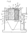
- number 1 shows a generally square section tank preferably made of reinforced concrete.
- the bottom 2 of the tank has a frusto-pyramidal shape that collects sludge resulting from a depuration.
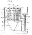
- the cylindrical panels are concentric and each of them is formed by two spaced apart walls 6 defining a space 7 for collecting the filtered liquid.
- the walls 6 are formed by filter screens. In the example shown in figures 1 and 2, the walls are parallel to each other so that space 7 width is constant.
- the two walls 6 are kept at a distance for forming said space 7, by a metal frame 9.
- Each space 7 has a metal sheet closed bottom 10 provided by the frame 9 so that each space 7 is completely isolated by the area containing the water to be filtered.
- a bore 11 is provided on each closed bottom 10, the bore being connected through a drainage conduit 12 to a conduit 13 for collecting the filtered liquid.
- a post 14 is connected to the metal frame 4 in the spider centre.
- a wheel 15 provided with a driving unit 16, is mounted on the top of post 14.
- the wheel rotational axis is coaxial to the vertical axis of the concentric panels 5.
- the wheel 15 supports one or more manifolds 17 (four in the example shown) fed by a distributor 18 of clean or filtered water on the fifth wheel and supplied by a conduit 19 closed by a valve 20.
- Clean or filtered water can be also supplied from the bottom through the metal frame 4 and the post 14 which should be formed of tubular elements.
- Each manifold 17 is provided with a vertical flushing column 21 inserted into at least one of the filtered water collecting spaces 7 and extending to the floor of the same space adjacent to the sheet closed bottom 10.
- Each flushing column is provided with a plurality of nozzles 22 arranged in two opposed vertical rows in order to act at the same time against the two filter walls 6 forming the panel.
- spaces 7 of greater diameters receive several vertical flushing columns 21 supported and fed through different manifolds.
- the nozzle flow is opposite to the purified water flow.
- a safety level meter 23 for the water to be filtered is located at the highest level said water can reach before entering the purified water collecting spaces.
- the water to be filtered is fed to the tank 1 through the supplying channel 24. After the liquid to be filtered has reached the level meter 23, the driving unit will be started and the pump 20 will be opened in order to initiate the counterflow flushing operation of the filter walls. The flushing water will partially remain in spaces 7 and partially flow through the filter screens dropping the sludge into the frusto-conical collecting bottom.
- the flushing operation is not stopped by the filtration process.
- the sludge consolidating in the frusto-pyramidal bottom is taken out through a sludge extraction bore 25 by an auger, a suitable pump, or other known conveying means.
- the two filter panel walls 6a are not parallel but converge to the bottom so that the distance of the flushing nozzles to the filter walls is smaller in the bottom area where sludge is highly concentrated.
- the operation of the flushing apparatus can be cyclically or continuously programmed since it does not interrupt the filtration process.
- Every cylindrical panel can be unitary or can be made up of sections.
- an air blowing apparatus for cleaning the filter walls which promotes the cleaning step after the operation of the flushing apparatus.
- the blowing apparatus is substantially the same of the flushing apparatus and it is provided with vertical columns which are insertable and movable in said spaces 7.
- the compressed air cleaning cycle must be preferably, but not exclusively, performed when the level of the liquid to be filtered is too shallow, for example during the night when the flow rate of the inflowing liquids to be filtered is too low or substantially zero.
- the filtration apparatuses for high flow rates can be made with rectangular tanks receiving many assemblies of concentric filter panels.
Landscapes
- Chemical & Material Sciences (AREA)
- Chemical Kinetics & Catalysis (AREA)
- Filtration Of Liquid (AREA)
- Separation Using Semi-Permeable Membranes (AREA)
- Treatment Of Sludge (AREA)
- Fluid-Pressure Circuits (AREA)
Applications Claiming Priority (2)
| Application Number | Priority Date | Filing Date | Title |
|---|---|---|---|
| ITPR000069 | 2000-12-21 | ||
| IT2000PR000069A ITPR20000069A1 (it) | 2000-12-21 | 2000-12-21 | Impianto di filtrazione statica di liquidi. |
Publications (2)
| Publication Number | Publication Date |
|---|---|
| EP1219334A1 EP1219334A1 (en) | 2002-07-03 |
| EP1219334B1 true EP1219334B1 (en) | 2006-05-24 |
Family
ID=11453447
Family Applications (1)
| Application Number | Title | Priority Date | Filing Date |
|---|---|---|---|
| EP01129473A Expired - Lifetime EP1219334B1 (en) | 2000-12-21 | 2001-12-11 | Back-flushable liquid static filtration apparatus |
Country Status (5)
| Country | Link |
|---|---|
| EP (1) | EP1219334B1 (it) |
| AT (1) | ATE327022T1 (it) |
| DE (1) | DE60119880T2 (it) |
| ES (1) | ES2265385T3 (it) |
| IT (1) | ITPR20000069A1 (it) |
Families Citing this family (2)
| Publication number | Priority date | Publication date | Assignee | Title |
|---|---|---|---|---|
| ITPR20060044A1 (it) * | 2006-05-17 | 2007-11-18 | Allegri Geom Primo S R L | Impianto di filtrazione statica di liquidi. |
| CN101983750B (zh) * | 2010-12-23 | 2014-08-06 | 中信重工机械股份有限公司 | 一种用于立盘过滤机的高液位喷淋进料装置 |
Family Cites Families (3)
| Publication number | Priority date | Publication date | Assignee | Title |
|---|---|---|---|---|
| DE3902829A1 (de) * | 1989-01-31 | 1990-08-02 | Linde Ag | Rueckspuelbarer filter |
| DE3905113A1 (de) * | 1989-02-20 | 1990-08-23 | H E T Filtertechnik Gmbh | Verfahren zur abreinigung von filterflaechen |
| IT1296402B1 (it) * | 1997-10-09 | 1999-06-25 | Allegri Geom Primo S R L | Impianto di filtrazione statica dei liquidi. |
-
2000
- 2000-12-21 IT IT2000PR000069A patent/ITPR20000069A1/it unknown
-
2001
- 2001-12-11 AT AT01129473T patent/ATE327022T1/de not_active IP Right Cessation
- 2001-12-11 EP EP01129473A patent/EP1219334B1/en not_active Expired - Lifetime
- 2001-12-11 DE DE60119880T patent/DE60119880T2/de not_active Expired - Fee Related
- 2001-12-11 ES ES01129473T patent/ES2265385T3/es not_active Expired - Lifetime
Also Published As
| Publication number | Publication date |
|---|---|
| EP1219334A1 (en) | 2002-07-03 |
| DE60119880D1 (de) | 2006-06-29 |
| ES2265385T3 (es) | 2007-02-16 |
| ITPR20000069A0 (it) | 2000-12-21 |
| ITPR20000069A1 (it) | 2002-06-21 |
| DE60119880T2 (de) | 2007-05-03 |
| ATE327022T1 (de) | 2006-06-15 |
Similar Documents
| Publication | Publication Date | Title |
|---|---|---|
| FI72048B (fi) | Vaetskefiltreranlaeggning och filteringsanordning | |
| FI90500B (fi) | Ennaltamäärättyä suurikokoisemman hienojakoisen aineen poistoon tarkoitettu vedenselkeytyslaitteisto | |
| JP2599767Y2 (ja) | 内圧形ろ過膜による原液のろ過装置 | |
| US6926839B2 (en) | Method and apparatus for removing particulate contaminants from commercial laundry waste water | |
| US4765889A (en) | Moving bridge filter - telescoping floating pot skimmer | |
| EP1219334A1 (en) | Back-flushable Liquid Static filtration apparatus | |
| RU2254297C2 (ru) | Установка для флотационно-фильтрационной очистки воды | |
| CN111871012A (zh) | 一种工业污水处理用沉降装置及其实施方法 | |
| US4966718A (en) | Cross flow filter method | |
| CN2562835Y (zh) | 一种减压自吸式气浮油水分离装置 | |
| CN113318854A (zh) | 一种盾构渣土环保处理装备 | |
| KR102733027B1 (ko) | 여과망 접촉 차단 가이드 벽체가 구비된 부상슬러지와 침전슬러지의 연속 분리 배출 장치 | |
| JP4198299B2 (ja) | 汚水処理装置 | |
| CN214455275U (zh) | 一种金刚石浮选中自动给料装置 | |
| CN213077724U (zh) | 一种水污染过滤净化防治机 | |
| CN218501389U (zh) | 一种用于分离絮凝物的过滤装置 | |
| US6149827A (en) | Device for separating particles from a particle containing liquid and a method for cleaning such a device | |
| CN118751046B (zh) | 一种湿法脱硫浆液自动化除油系统 | |
| CN220295344U (zh) | 一种机床刀具用清洗装置 | |
| CN220345262U (zh) | 一种沙水分离设备 | |
| SU973142A1 (ru) | Устройство дл совместной подготовки газа,нефти и воды | |
| CN222717013U (zh) | 一种混凝土输送泵 | |
| CN220779147U (zh) | 一种水力澄清器 | |
| CN215781876U (zh) | 一种城市污水处理用固液分离装置 | |
| CN218794185U (zh) | 一种混凝土泵管清洗余料收集分选装置 |
Legal Events
| Date | Code | Title | Description |
|---|---|---|---|
| PUAI | Public reference made under article 153(3) epc to a published international application that has entered the european phase |
Free format text: ORIGINAL CODE: 0009012 |
|
| AK | Designated contracting states |
Kind code of ref document: A1 Designated state(s): AT BE CH CY DE DK ES FI FR GB GR IE IT LI LU MC NL PT SE TR |
|
| AX | Request for extension of the european patent |
Free format text: AL;LT;LV;MK;RO;SI |
|
| 17P | Request for examination filed |
Effective date: 20020905 |
|
| AKX | Designation fees paid |
Designated state(s): AT BE CH CY DE DK ES FI FR GB GR IE IT LI LU MC NL PT SE TR |
|
| RAP1 | Party data changed (applicant data changed or rights of an application transferred) |
Owner name: ALLEGRI GEOM. PRIMO S.R.L. |
|
| 17Q | First examination report despatched |
Effective date: 20050322 |
|
| GRAP | Despatch of communication of intention to grant a patent |
Free format text: ORIGINAL CODE: EPIDOSNIGR1 |
|
| RTI1 | Title (correction) |
Free format text: BACK-FLUSHABLE LIQUID STATIC FILTRATION APPARATUS |
|
| GRAS | Grant fee paid |
Free format text: ORIGINAL CODE: EPIDOSNIGR3 |
|
| GRAA | (expected) grant |
Free format text: ORIGINAL CODE: 0009210 |
|
| AK | Designated contracting states |
Kind code of ref document: B1 Designated state(s): AT BE CH CY DE DK ES FI FR GB GR IE IT LI LU MC NL PT SE TR |
|
| PG25 | Lapsed in a contracting state [announced via postgrant information from national office to epo] |
Ref country code: FI Free format text: LAPSE BECAUSE OF FAILURE TO SUBMIT A TRANSLATION OF THE DESCRIPTION OR TO PAY THE FEE WITHIN THE PRESCRIBED TIME-LIMIT Effective date: 20060524 Ref country code: AT Free format text: LAPSE BECAUSE OF FAILURE TO SUBMIT A TRANSLATION OF THE DESCRIPTION OR TO PAY THE FEE WITHIN THE PRESCRIBED TIME-LIMIT Effective date: 20060524 |
|
| REG | Reference to a national code |
Ref country code: GB Ref legal event code: FG4D |
|
| REG | Reference to a national code |
Ref country code: CH Ref legal event code: EP |
|
| REG | Reference to a national code |
Ref country code: IE Ref legal event code: FG4D |
|
| REF | Corresponds to: |
Ref document number: 60119880 Country of ref document: DE Date of ref document: 20060629 Kind code of ref document: P |
|
| REG | Reference to a national code |
Ref country code: CH Ref legal event code: NV Representative=s name: R. A. EGLI & CO. PATENTANWAELTE |
|
| PG25 | Lapsed in a contracting state [announced via postgrant information from national office to epo] |
Ref country code: SE Free format text: LAPSE BECAUSE OF FAILURE TO SUBMIT A TRANSLATION OF THE DESCRIPTION OR TO PAY THE FEE WITHIN THE PRESCRIBED TIME-LIMIT Effective date: 20060824 Ref country code: DK Free format text: LAPSE BECAUSE OF FAILURE TO SUBMIT A TRANSLATION OF THE DESCRIPTION OR TO PAY THE FEE WITHIN THE PRESCRIBED TIME-LIMIT Effective date: 20060824 |
|
| PG25 | Lapsed in a contracting state [announced via postgrant information from national office to epo] |
Ref country code: PT Free format text: LAPSE BECAUSE OF FAILURE TO SUBMIT A TRANSLATION OF THE DESCRIPTION OR TO PAY THE FEE WITHIN THE PRESCRIBED TIME-LIMIT Effective date: 20061024 |
|
| ET | Fr: translation filed | ||
| PG25 | Lapsed in a contracting state [announced via postgrant information from national office to epo] |
Ref country code: IE Free format text: LAPSE BECAUSE OF NON-PAYMENT OF DUE FEES Effective date: 20061211 |
|
| PG25 | Lapsed in a contracting state [announced via postgrant information from national office to epo] |
Ref country code: MC Free format text: LAPSE BECAUSE OF NON-PAYMENT OF DUE FEES Effective date: 20061231 |
|
| REG | Reference to a national code |
Ref country code: ES Ref legal event code: FG2A Ref document number: 2265385 Country of ref document: ES Kind code of ref document: T3 |
|
| PLBE | No opposition filed within time limit |
Free format text: ORIGINAL CODE: 0009261 |
|
| STAA | Information on the status of an ep patent application or granted ep patent |
Free format text: STATUS: NO OPPOSITION FILED WITHIN TIME LIMIT |
|
| 26N | No opposition filed |
Effective date: 20070227 |
|
| PGFP | Annual fee paid to national office [announced via postgrant information from national office to epo] |
Ref country code: ES Payment date: 20071126 Year of fee payment: 7 Ref country code: NL Payment date: 20071223 Year of fee payment: 7 |
|
| PG25 | Lapsed in a contracting state [announced via postgrant information from national office to epo] |
Ref country code: GR Free format text: LAPSE BECAUSE OF FAILURE TO SUBMIT A TRANSLATION OF THE DESCRIPTION OR TO PAY THE FEE WITHIN THE PRESCRIBED TIME-LIMIT Effective date: 20060825 |
|
| PGFP | Annual fee paid to national office [announced via postgrant information from national office to epo] |
Ref country code: CH Payment date: 20080326 Year of fee payment: 7 Ref country code: GB Payment date: 20071121 Year of fee payment: 7 |
|
| PGFP | Annual fee paid to national office [announced via postgrant information from national office to epo] |
Ref country code: DE Payment date: 20080221 Year of fee payment: 7 |
|
| PG25 | Lapsed in a contracting state [announced via postgrant information from national office to epo] |
Ref country code: LU Free format text: LAPSE BECAUSE OF NON-PAYMENT OF DUE FEES Effective date: 20061211 Ref country code: TR Free format text: LAPSE BECAUSE OF FAILURE TO SUBMIT A TRANSLATION OF THE DESCRIPTION OR TO PAY THE FEE WITHIN THE PRESCRIBED TIME-LIMIT Effective date: 20060524 |
|
| PGFP | Annual fee paid to national office [announced via postgrant information from national office to epo] |
Ref country code: FR Payment date: 20071220 Year of fee payment: 7 |
|
| PGFP | Annual fee paid to national office [announced via postgrant information from national office to epo] |
Ref country code: BE Payment date: 20071231 Year of fee payment: 7 |
|
| PG25 | Lapsed in a contracting state [announced via postgrant information from national office to epo] |
Ref country code: CY Free format text: LAPSE BECAUSE OF FAILURE TO SUBMIT A TRANSLATION OF THE DESCRIPTION OR TO PAY THE FEE WITHIN THE PRESCRIBED TIME-LIMIT Effective date: 20060524 |
|
| BERE | Be: lapsed |
Owner name: *ALLEGRI GEOM. PRIMO S.R.L. Effective date: 20081231 |
|
| REG | Reference to a national code |
Ref country code: CH Ref legal event code: PL |
|
| GBPC | Gb: european patent ceased through non-payment of renewal fee |
Effective date: 20081211 |
|
| NLV4 | Nl: lapsed or anulled due to non-payment of the annual fee |
Effective date: 20090701 |
|
| PG25 | Lapsed in a contracting state [announced via postgrant information from national office to epo] |
Ref country code: BE Free format text: LAPSE BECAUSE OF NON-PAYMENT OF DUE FEES Effective date: 20081231 |
|
| REG | Reference to a national code |
Ref country code: FR Ref legal event code: ST Effective date: 20090831 |
|
| PG25 | Lapsed in a contracting state [announced via postgrant information from national office to epo] |
Ref country code: CH Free format text: LAPSE BECAUSE OF NON-PAYMENT OF DUE FEES Effective date: 20081231 Ref country code: DE Free format text: LAPSE BECAUSE OF NON-PAYMENT OF DUE FEES Effective date: 20090701 Ref country code: LI Free format text: LAPSE BECAUSE OF NON-PAYMENT OF DUE FEES Effective date: 20081231 |
|
| PG25 | Lapsed in a contracting state [announced via postgrant information from national office to epo] |
Ref country code: NL Free format text: LAPSE BECAUSE OF NON-PAYMENT OF DUE FEES Effective date: 20090701 Ref country code: GB Free format text: LAPSE BECAUSE OF NON-PAYMENT OF DUE FEES Effective date: 20081211 |
|
| REG | Reference to a national code |
Ref country code: ES Ref legal event code: FD2A Effective date: 20081212 |
|
| PG25 | Lapsed in a contracting state [announced via postgrant information from national office to epo] |
Ref country code: ES Free format text: LAPSE BECAUSE OF NON-PAYMENT OF DUE FEES Effective date: 20081212 Ref country code: FR Free format text: LAPSE BECAUSE OF NON-PAYMENT OF DUE FEES Effective date: 20081231 |
|
| PGFP | Annual fee paid to national office [announced via postgrant information from national office to epo] |
Ref country code: IT Payment date: 20101217 Year of fee payment: 10 |
|
| PG25 | Lapsed in a contracting state [announced via postgrant information from national office to epo] |
Ref country code: IT Free format text: LAPSE BECAUSE OF NON-PAYMENT OF DUE FEES Effective date: 20131231 |
|
| PG25 | Lapsed in a contracting state [announced via postgrant information from national office to epo] |
Ref country code: IT Free format text: LAPSE BECAUSE OF NON-PAYMENT OF DUE FEES Effective date: 20131211 |