EP1217308A1 - Dunstabzugshaube - Google Patents
Dunstabzugshaube Download PDFInfo
- Publication number
- EP1217308A1 EP1217308A1 EP01128909A EP01128909A EP1217308A1 EP 1217308 A1 EP1217308 A1 EP 1217308A1 EP 01128909 A EP01128909 A EP 01128909A EP 01128909 A EP01128909 A EP 01128909A EP 1217308 A1 EP1217308 A1 EP 1217308A1
- Authority
- EP
- European Patent Office
- Prior art keywords
- extractor hood
- suction
- suction funnel
- funnel
- filter
- Prior art date
- Legal status (The legal status is an assumption and is not a legal conclusion. Google has not performed a legal analysis and makes no representation as to the accuracy of the status listed.)
- Granted
Links
- 239000000779 smoke Substances 0.000 title 1
- 230000000694 effects Effects 0.000 claims abstract description 7
- 238000000605 extraction Methods 0.000 claims abstract description 7
- 239000002184 metal Substances 0.000 claims description 10
- 238000010411 cooking Methods 0.000 claims description 4
- 238000011045 prefiltration Methods 0.000 claims description 2
- 239000003517 fume Substances 0.000 description 4
- 230000015572 biosynthetic process Effects 0.000 description 2
- 238000010438 heat treatment Methods 0.000 description 2
- 238000009413 insulation Methods 0.000 description 2
- 238000002955 isolation Methods 0.000 description 2
- 239000000463 material Substances 0.000 description 2
- 230000006978 adaptation Effects 0.000 description 1
- 238000011109 contamination Methods 0.000 description 1
- 230000001419 dependent effect Effects 0.000 description 1
- 238000009422 external insulation Methods 0.000 description 1
- 239000004519 grease Substances 0.000 description 1
- 239000002244 precipitate Substances 0.000 description 1
- 229920006395 saturated elastomer Polymers 0.000 description 1
- 230000006641 stabilisation Effects 0.000 description 1
- 238000011105 stabilization Methods 0.000 description 1
Images



Classifications
-
- F—MECHANICAL ENGINEERING; LIGHTING; HEATING; WEAPONS; BLASTING
- F24—HEATING; RANGES; VENTILATING
- F24C—DOMESTIC STOVES OR RANGES ; DETAILS OF DOMESTIC STOVES OR RANGES, OF GENERAL APPLICATION
- F24C15/00—Details
- F24C15/20—Removing cooking fumes
- F24C15/2078—Removing cooking fumes movable
Definitions
- the invention relates to an extractor hood, in which the suction of the vapors and Vapors are related to the hotplate.
- an extractor hood which has means for a Sliding and / or rotating movement for the purpose of movable attachment.
- Slide rails, rollers and hinges are used. That’s it it is possible to close the extractor hood above and over the hotplates move to an intense one over the hotplates in use To aspirate the vapors and vapors. There is also a fold up on the Wall possible.
- an extractor hood is known from DE 41 42 474 A1, the divided one Extraction parts with horizontally arranged filters for extracting the vapors and vapors on the one hand for the front hotplates and on the other hand for the rear hotplates of the Cooker has.
- An extractor hood with at least three parts is used, two Parts of the separate air duct and the third part serve the fume cupboard Suction fans represents.
- the suction parts can be operated separately or together. With separate Extraction, each suction fan is driven by its own motor, otherwise one motor is sufficient for the two suction fans.
- this extractor hood is made of three parts is composed, with at least the two suction parts in itself must be designed to prevent the suction of fumes and To prevent vapors. That makes the extractor hood difficult.
- an extractor hood is on the cooking area side arranged in front of the filter of the extractor hood, the suction opening points towards the hob.
- the extractor hood can be moved in the horizontal filter level or displaceable and pivotable downwards relative to the filter level and changeable in altitude. Extracting the vapors and vapors through the hood is done by the fan system of the extractor hood via a hose or the extractor hood has its own additional filter and fan system.
- the Disadvantages of this solution are the cost of the additional filter and Fan system and secondly in the use of the hose for suction. This is dirty light and will therefore find little acceptance in the household.
- the extractor device according to DE 199 07 057 A1 is in the kitchen worktop arranged sunk. It is extended to the suction mode and to Food carrier swung in. Their disadvantage is at least that the open space of the Kitchen worktop is restricted.
- the object of the invention is to extract the fumes from the cooking point To improve vapors. This object is achieved with the features of claim 1. advantageous embodiments are the subject of the dependent claims.
- the filter surface of the filter is in partial filter surfaces separate suction shaft and each partial filter surface is a fan suction nozzle or assigned a fan blower, the speed of the fan blower independent should be controllable from each other.
- the suction funnel with the control for the speed of the fan blower coupled, the partial filter surface where the suction funnel is located can be optimal be sucked off.
- the design of the suction funnel is also of major importance for the Effectiveness of the extractor hood according to the invention.
- the suction funnel has a trumpet shape or is asymmetrical, or is a double funnel, or has a perforated outer surface.
- the Suction funnels inside have air baffles on the outer surface, which are preferred are arranged spirally.
- the material of the suction funnel is also important for its effectiveness.
- the invention therefore provides that the suction funnel is preferably made of metal or externally insulated metal or externally heated metal or externally heated Metal is made with an insulating layer above.
- the invention provides that the suction funnel in the Suction funnel height is adjustable. This can be easily achieved by the casing of the suction funnel is composed like an iris or out section overlapping truncated cone sections.
- the suction funnel arrangement according to the invention offers the possibility of that the suction funnel is equipped with a prefilter, preferably one with a small flow resistance, and / or in the area of the suction opening of the Suction funnel to arrange a circumferential condensate / grease trap inside.
- the extractor hood 1 shown in Fig. 1 consists of the housing 2 with the inside arranged filter frame 4 with filter 3. Below the filter 3 is the suction funnel 5 arranged with a clear distance A to the filter 3. The suction funnel 5 is on one pivoted pivot lever 10 out, which is arranged centrally in the frame of the filter 3 is. By simply swiveling the filter, the partial filter surfaces 3.1 - 3.4 be assigned.
- the extractor hood 1 is made of four sheets Duct spaces divided, and each partial filter area 3.1 - 3.4 is a fan suction nozzle 9 assigned. It is also possible for each of these subspaces to have its own fan blower 8 assigned. The speed of the fan blowers 8 can be controlled independently of one another.
- the suction funnel 5 is coupled to the control for the speed of the fan blower 8, such that the partial filter surfaces 3.1 - 3.4 correspond to the position of the suction funnel 5, which is located in the illustration at the partial filter area 3.1, optimally suctioned off become.
- the extractor hood 1 has in the area below the filter 3 on the hob side of the filter frame 4 lying opposite to one another parallel to its outer edges Guide rails 13 on.
- the guide rails are by at least one Cross rail 14 connected to each other, the cross rail 14 along the guide rails 13 is displaceable and the suction funnel 5 along the cross rail 14.
- the distance A is dimensioned such that the suction fan (s) 8 generate a suction effect in the suction funnel 5 in the extractor hood 1.
- the trumpet shape shown in Fig. 2 for the suction funnel 5 supports the Chimney effect. It prevents swirling of the boundary layer, which means little saturated air sweeps past the funnel surface, which leads to less condensate.
- the suction funnel shown in Fig. 3 is perforated.
- the openings in the direction of flow prevent condensate from being deposited by supplying unsaturated room air.
- the asymmetrical suction funnel 5 shown in FIG. 4 enables an additional one Rotate away from the work area or into the vapor area.
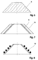
- the suction funnel 5 in Fig. 5 consists of a double funnel and is characterized by good vacuum generation in the upper suction area.
- the suction funnel 5 with air guiding orifices shown in FIG. 6 leads to stabilization of the fumes below the funnel.
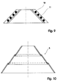
- the suction funnel 5 is preferably made of metal. This allows a quick adaptation to the steam temperature, which the Condensate failure reduced. Furthermore, the suction funnel 5 made of metal on the outside Have insulation 11, as shown in Fig. 7. The material in the boundary layer to Steam heats up even faster here, which further reduces the condensate failure. In addition, it is also possible to heat the suction funnel 5 or the heater 12 to isolate the outside additionally. This is shown in FIGS. 8 and 9.
- Suction funnel 5 is adjustable in funnel height.
- Such training, once composed of sections of truncated cone and once by an iris formation are shown in Figs. 10 and 11.
Landscapes
- Engineering & Computer Science (AREA)
- Chemical & Material Sciences (AREA)
- Combustion & Propulsion (AREA)
- Mechanical Engineering (AREA)
- General Engineering & Computer Science (AREA)
- Ventilation (AREA)
- Filtering Of Dispersed Particles In Gases (AREA)
- Superstructure Of Vehicle (AREA)
Abstract
Description
- Fig. 1:
- Dunstabzugshaube mit verschwenkbarem Absaugtrichter,
- Fig. 2:
- Dunstabzugshaube mit verschiebbarem Absaugtrichter,
- Fig. 3:
- perforierter Absaugtrichter,
- Fig. 4:
- asymmetrischer Absaugtrichter,
- Fig. 5:
- Absaugtrichter als Doppeltrichter ausgebildet,
- Fig. 6:
- Absaugtrichter mit Luftleitblenden,
- Fig. 7:
- Absaugtrichter mit äußerer Isolation,
- Fig. 8:
- Absaugtrichter mit Heizung,
- Fig. 9:
- Absaugtrichter mit Heizung und Isolation,
- Fig. 10:
- ringförmig zusammengesetzter Absaugtrichter und
- Fig. 11:
- als Irisblende ausgeführter Absaugtrichter.
Claims (17)
- Dunstabzugshaube mit Einzelkochstellenabsaugung, bei der eine Abzugshaube kochstellenseitig vor dem Filter der Dunstabzugshaube angeordnet ist, deren Ansaugöffnung in Richtung Kochstelle weist, die Abzugshaube in der waagerechten Filterebene verschiebbar oder verschieb- und gegenüber der Filterebene nach unten verschwenkbar ist und das Absaugen der Dünste und Wrasen über die Abzugshaube durch das Lüftersystem der Dunstabzugshaube erfolgt, dadurch gekennzeichnet, dass die Abzugshaube als Absaugtrichter (5) ausgebildet ist und zwischen der gegenüber der Ansaugöffnung (6) kleineren Austrittsöffnung (7) des Absaugtrichters (5) und dem Filter (3) der Dunstabzugshaube (1) ein lichter Abstand A besteht, wobei der Abstand A, die Lüftergebläseleistung und der Absaugtrichter (5) so aufeinander abgestimmt ausgelegt sind, dass das oder die saugenden Lüftergebläse (8) in der Dunstabzugshaube (1) eine Sogwirkung im Absaugtrichter (5) erzeugen.
- Dunstabzugshaube nach Anspruch 1, dadurch gekennzeichnet, dass die Filterfläche des Filters (3) in Teilfilterflächen (3.1 - 3.4) mit eigenem Absaugschacht aufgeteilt ist und jeder Teilfilterfläche (3n) eine Lüfteransaugdüse (9) oder ein Lüftergebläse (8) zugeordnet ist.
- Dunstabzugshaube nach Anspruch 2, dadurch gekennzeichnet, dass die Drehzahl der Lüftergebläse (8) unabhängig voneinander steuerbar ist.
- Dunstabzugshaube nach Anspruch 3, dadurch gekennzeichnet, dass der Absaugtrichter (5) mit der Steuerung für die Drehzahl der Lüftergebläse (8) gekoppelt ist, derart, das die Teilfilterfläche (3n), bei der sich der Absaugtrichter (5) befindet, optimal abgesaugt wird.
- Dunstabzugshaube nach mindestens einem der Ansprüche 1 bis 4, dadurch gekennzeichnet, dass der Absaugtrichter (5) an einem unterhalb der Filterebene waagerecht verschwenkbaren Schwenkhebel (10) angeordnet ist.
- Dunstabzugshaube nach Anspruch 5, dadurch gekennzeichnet, dass der Schwenkhebel (10) mittig im Rahmen des Filters (3) geführt ist.
- Dunstabzugshaube nach Anspruch 1, dadurch gekennzeichnet, dass der Absaugtrichter (5) eine Trompetenform aufweist.
- Dunstabzugshaube nach Anspruch 1, dadurch gekennzeichnet, dass der Absaugtrichter (5) asymmetrisch ausgebildet ist.
- Dunstabzugshaube nach Anspruch 1, dadurch gekennzeichnet, dass der Absaugtrichter (5) als Doppeltrichter ausgebildet ist.
- Dunstabzugshaube nach Anspruch 1, dadurch gekennzeichnet, dass der Absaugtrichter (5) eine perforierte Mantelfläche aufweist.
- Dunstabzugshaube nach Anspruch 1, dadurch gekennzeichnet, dass der Absaugtrichter (5) innen Luftleitblenden an der Mantelfläche aufweist, die bevorzugt spiralförmig angeordnet sind.
- Dunstabzugshaube nach mindestens einem der Ansprüche 1 bis 11, dadurch gekennzeichnet, dass der Absaugtrichter (5) aus Metall oder aus außen isoliertem Metall oder aus außen beheiztem Metall oder aus außen beheiztem Metall mit einer darüber befindlichen Isolierschicht (11) gefertigt ist.
- Dunstabzugshaube nach mindestens einem der Ansprüche 1 bis 12, dadurch gekennzeichnet, dass der Absaugtrichter (5) in der Absaugtrichterhöhe verstellbar ist.
- Dunstabzugshaube nach Anspruch 13, dadurch gekennzeichnet, dass der Mantel des Absaugtrichters (5) wie eine Irisblende zusammengesetzt ist.
- Dunstabzugshaube nach mindestens einem der Ansprüche 1 bis 14, dadurch gekennzeichnet, dass der Mantel des Absaugtrichters (5) sich aus abschnittsweise überlagernden Kegelstumpfabschnitten zusammensetzt.
- Dunstabzugshaube nach mindestens einem der Ansprüche 1 bis 15, dadurch gekennzeichnet, dass der Absaugtrichter (5) mit einem Vorfilter ausgestattet ist, vorzugsweise einem mit einem kleinen Strömungswiderstand.
- Dunstabzugshaube nach mindestens einem der Ansprüche 1 bis 16, dadurch gekennzeichnet, dass der Absaugtrichter (5) im Bereich der Ansaugöffnung (6) innen eine umlaufende Kondensat-/Fettfangrinne aufweist.
Applications Claiming Priority (2)
| Application Number | Priority Date | Filing Date | Title |
|---|---|---|---|
| DE10064322 | 2000-12-22 | ||
| DE10064322A DE10064322A1 (de) | 2000-12-22 | 2000-12-22 | Dunstabzugshaube |
Publications (2)
| Publication Number | Publication Date |
|---|---|
| EP1217308A1 true EP1217308A1 (de) | 2002-06-26 |
| EP1217308B1 EP1217308B1 (de) | 2005-07-13 |
Family
ID=7668479
Family Applications (1)
| Application Number | Title | Priority Date | Filing Date |
|---|---|---|---|
| EP01128909A Expired - Lifetime EP1217308B1 (de) | 2000-12-22 | 2001-12-05 | Dunstabzugshaube |
Country Status (3)
| Country | Link |
|---|---|
| EP (1) | EP1217308B1 (de) |
| AT (1) | ATE299575T1 (de) |
| DE (2) | DE10064322A1 (de) |
Cited By (1)
| Publication number | Priority date | Publication date | Assignee | Title |
|---|---|---|---|---|
| EP2072907A3 (de) * | 2007-12-18 | 2012-08-01 | Miele & Cie. KG | Dunstabzugsvorrichtung |
Families Citing this family (1)
| Publication number | Priority date | Publication date | Assignee | Title |
|---|---|---|---|---|
| DE102005013806A1 (de) * | 2005-03-24 | 2006-09-28 | BSH Bosch und Siemens Hausgeräte GmbH | Dunstabzugshaube |
Citations (5)
| Publication number | Priority date | Publication date | Assignee | Title |
|---|---|---|---|---|
| DE1883153U (de) | 1963-03-21 | 1963-11-21 | Siemens Elektrogeraete Gmbh | Dunstabzughaube. |
| DE7522877U (de) * | 1975-07-18 | 1975-11-13 | Sueddeutsche Metallwerke Gmbh | Dunstabzugshaube |
| DE4142474A1 (de) | 1991-12-20 | 1993-06-24 | Bosch Siemens Hausgeraete | Dunstabzugshaube |
| DE19810818A1 (de) | 1998-03-12 | 1999-09-16 | Fink Karl Eisfink | Dunstabzugshaube |
| DE19907057A1 (de) | 1999-02-19 | 2000-08-24 | Bsh Bosch Siemens Hausgeraete | Dunstabzugsvorrichtung, angeordnet im Bereich neben offenen Garungsbereichen |
Family Cites Families (2)
| Publication number | Priority date | Publication date | Assignee | Title |
|---|---|---|---|---|
| DE4142477C2 (de) * | 1991-12-20 | 1994-06-01 | Bosch Siemens Hausgeraete | Dunstabzugsvorrichtung |
| DE4201209C2 (de) * | 1992-01-18 | 1994-06-01 | Miele & Cie | Dunstabzugsvorrichtung zur Anordnung über dem Kochfeld eines Küchenherdes |
-
2000
- 2000-12-22 DE DE10064322A patent/DE10064322A1/de not_active Withdrawn
-
2001
- 2001-12-05 EP EP01128909A patent/EP1217308B1/de not_active Expired - Lifetime
- 2001-12-05 DE DE50106729T patent/DE50106729D1/de not_active Expired - Lifetime
- 2001-12-05 AT AT01128909T patent/ATE299575T1/de not_active IP Right Cessation
Patent Citations (5)
| Publication number | Priority date | Publication date | Assignee | Title |
|---|---|---|---|---|
| DE1883153U (de) | 1963-03-21 | 1963-11-21 | Siemens Elektrogeraete Gmbh | Dunstabzughaube. |
| DE7522877U (de) * | 1975-07-18 | 1975-11-13 | Sueddeutsche Metallwerke Gmbh | Dunstabzugshaube |
| DE4142474A1 (de) | 1991-12-20 | 1993-06-24 | Bosch Siemens Hausgeraete | Dunstabzugshaube |
| DE19810818A1 (de) | 1998-03-12 | 1999-09-16 | Fink Karl Eisfink | Dunstabzugshaube |
| DE19907057A1 (de) | 1999-02-19 | 2000-08-24 | Bsh Bosch Siemens Hausgeraete | Dunstabzugsvorrichtung, angeordnet im Bereich neben offenen Garungsbereichen |
Cited By (1)
| Publication number | Priority date | Publication date | Assignee | Title |
|---|---|---|---|---|
| EP2072907A3 (de) * | 2007-12-18 | 2012-08-01 | Miele & Cie. KG | Dunstabzugsvorrichtung |
Also Published As
| Publication number | Publication date |
|---|---|
| ATE299575T1 (de) | 2005-07-15 |
| DE50106729D1 (de) | 2005-08-18 |
| DE10064322A1 (de) | 2002-07-04 |
| EP1217308B1 (de) | 2005-07-13 |
Similar Documents
| Publication | Publication Date | Title |
|---|---|---|
| EP3827204B1 (de) | Kochfeldsystem | |
| EP3338031B1 (de) | Kombinationsgerät mit kochfeld und dunstabzugsvorrichtung | |
| EP1194721B1 (de) | Luftabsaugvorrichtung für einen arbeitsplatz | |
| EP3911895B1 (de) | Kochfeldsystem | |
| CH682512A5 (de) | Dampfabzugeinrichtung. | |
| DE102018130828A1 (de) | Dunstabzug | |
| DE202008013350U1 (de) | Vorrichtung zum Kochen mit Spül-Luftzuführung und Spül-Luftabsaugung | |
| DE102008050723A1 (de) | Vorrichtung zum Kochen mit Spül-Luftzuführung und Spül-Luftabsaugung | |
| EP3136004A1 (de) | Kombinationsgerät mit kochfeld und dunstabzugsvorrichtung | |
| DE3436999A1 (de) | Dunstabzugsvorrichtung zur anordnung ueber dem kochfeld eines kuechenherdes o.dgl. | |
| DE2259670A1 (de) | Abzugshaube, insbesondere fuer kuechenherde | |
| EP1696180A2 (de) | Absaugvorrichtung für eine Kocheinrichtung, insbesondere ein Kochfeld oder dergleichen | |
| EP2210048B1 (de) | Dunstabzugsvorrichtung | |
| EP2829808B1 (de) | Dunstabzugshaube | |
| EP1217308B1 (de) | Dunstabzugshaube | |
| EP0886112A2 (de) | Kombinierte Klimatisier- und Dunsthaube | |
| EP3599427B1 (de) | Kochfeldysytem | |
| DE102012216078A1 (de) | Dunstabzugsvorrichtung mit Dunstabzugshaube und Luftführungsvorrichtung | |
| DE19950817A1 (de) | Dunstabzugsvorrichtung | |
| DE2106772A1 (de) | Herd, insbesondere Elektroherd | |
| DE102004055947A1 (de) | Dunstabzugshaube mit Einzelstellenbesaugung | |
| DE10015745A1 (de) | Dunstabzugsvorrichtung | |
| DE8905998U1 (de) | Gargerät | |
| DE4142477A1 (de) | Dunstabzugsvorrichtung | |
| EP3425282B1 (de) | Kombinationsgerät mit kochfeld und in dem kochfeld integrierter dunstabzugsvorrichtung |
Legal Events
| Date | Code | Title | Description |
|---|---|---|---|
| PUAI | Public reference made under article 153(3) epc to a published international application that has entered the european phase |
Free format text: ORIGINAL CODE: 0009012 |
|
| AK | Designated contracting states |
Kind code of ref document: A1 Designated state(s): AT BE CH CY DE DK ES FI FR GB GR IE IT LI LU MC NL PT SE TR |
|
| AX | Request for extension of the european patent |
Free format text: AL;LT;LV;MK;RO;SI |
|
| 17P | Request for examination filed |
Effective date: 20021227 |
|
| AKX | Designation fees paid |
Designated state(s): AT BE CH CY DE DK ES FI FR GB GR IE IT LI LU MC NL PT SE TR |
|
| RAP1 | Party data changed (applicant data changed or rights of an application transferred) |
Owner name: BSH BOSCH UND SIEMENS HAUSGERAETE GMBH |
|
| 17Q | First examination report despatched |
Effective date: 20040129 |
|
| GRAP | Despatch of communication of intention to grant a patent |
Free format text: ORIGINAL CODE: EPIDOSNIGR1 |
|
| GRAS | Grant fee paid |
Free format text: ORIGINAL CODE: EPIDOSNIGR3 |
|
| GRAA | (expected) grant |
Free format text: ORIGINAL CODE: 0009210 |
|
| AK | Designated contracting states |
Kind code of ref document: B1 Designated state(s): AT BE CH CY DE DK ES FI FR GB GR IE IT LI LU MC NL PT SE TR |
|
| PG25 | Lapsed in a contracting state [announced via postgrant information from national office to epo] |
Ref country code: IT Free format text: LAPSE BECAUSE OF FAILURE TO SUBMIT A TRANSLATION OF THE DESCRIPTION OR TO PAY THE FEE WITHIN THE PRESCRIBED TIME-LIMIT;WARNING: LAPSES OF ITALIAN PATENTS WITH EFFECTIVE DATE BEFORE 2007 MAY HAVE OCCURRED AT ANY TIME BEFORE 2007. THE CORRECT EFFECTIVE DATE MAY BE DIFFERENT FROM THE ONE RECORDED. Effective date: 20050713 Ref country code: ES Free format text: LAPSE BECAUSE OF FAILURE TO SUBMIT A TRANSLATION OF THE DESCRIPTION OR TO PAY THE FEE WITHIN THE PRESCRIBED TIME-LIMIT Effective date: 20050713 Ref country code: NL Free format text: LAPSE BECAUSE OF FAILURE TO SUBMIT A TRANSLATION OF THE DESCRIPTION OR TO PAY THE FEE WITHIN THE PRESCRIBED TIME-LIMIT Effective date: 20050713 Ref country code: FI Free format text: LAPSE BECAUSE OF FAILURE TO SUBMIT A TRANSLATION OF THE DESCRIPTION OR TO PAY THE FEE WITHIN THE PRESCRIBED TIME-LIMIT Effective date: 20050713 Ref country code: TR Free format text: LAPSE BECAUSE OF FAILURE TO SUBMIT A TRANSLATION OF THE DESCRIPTION OR TO PAY THE FEE WITHIN THE PRESCRIBED TIME-LIMIT Effective date: 20050713 Ref country code: IE Free format text: LAPSE BECAUSE OF FAILURE TO SUBMIT A TRANSLATION OF THE DESCRIPTION OR TO PAY THE FEE WITHIN THE PRESCRIBED TIME-LIMIT Effective date: 20050713 Ref country code: GB Free format text: LAPSE BECAUSE OF FAILURE TO SUBMIT A TRANSLATION OF THE DESCRIPTION OR TO PAY THE FEE WITHIN THE PRESCRIBED TIME-LIMIT Effective date: 20050713 |
|
| REG | Reference to a national code |
Ref country code: GB Ref legal event code: FG4D Free format text: NOT ENGLISH |
|
| REG | Reference to a national code |
Ref country code: CH Ref legal event code: EP |
|
| REG | Reference to a national code |
Ref country code: IE Ref legal event code: FG4D Free format text: LANGUAGE OF EP DOCUMENT: GERMAN |
|
| REF | Corresponds to: |
Ref document number: 50106729 Country of ref document: DE Date of ref document: 20050818 Kind code of ref document: P |
|
| PG25 | Lapsed in a contracting state [announced via postgrant information from national office to epo] |
Ref country code: GR Free format text: LAPSE BECAUSE OF FAILURE TO SUBMIT A TRANSLATION OF THE DESCRIPTION OR TO PAY THE FEE WITHIN THE PRESCRIBED TIME-LIMIT Effective date: 20051013 Ref country code: SE Free format text: LAPSE BECAUSE OF FAILURE TO SUBMIT A TRANSLATION OF THE DESCRIPTION OR TO PAY THE FEE WITHIN THE PRESCRIBED TIME-LIMIT Effective date: 20051013 Ref country code: DK Free format text: LAPSE BECAUSE OF FAILURE TO SUBMIT A TRANSLATION OF THE DESCRIPTION OR TO PAY THE FEE WITHIN THE PRESCRIBED TIME-LIMIT Effective date: 20051013 |
|
| PG25 | Lapsed in a contracting state [announced via postgrant information from national office to epo] |
Ref country code: CY Free format text: LAPSE BECAUSE OF FAILURE TO SUBMIT A TRANSLATION OF THE DESCRIPTION OR TO PAY THE FEE WITHIN THE PRESCRIBED TIME-LIMIT Effective date: 20051205 Ref country code: AT Free format text: LAPSE BECAUSE OF NON-PAYMENT OF DUE FEES Effective date: 20051205 |
|
| PG25 | Lapsed in a contracting state [announced via postgrant information from national office to epo] |
Ref country code: PT Free format text: LAPSE BECAUSE OF FAILURE TO SUBMIT A TRANSLATION OF THE DESCRIPTION OR TO PAY THE FEE WITHIN THE PRESCRIBED TIME-LIMIT Effective date: 20051219 |
|
| PG25 | Lapsed in a contracting state [announced via postgrant information from national office to epo] |
Ref country code: BE Free format text: LAPSE BECAUSE OF NON-PAYMENT OF DUE FEES Effective date: 20051231 Ref country code: MC Free format text: LAPSE BECAUSE OF NON-PAYMENT OF DUE FEES Effective date: 20051231 Ref country code: CH Free format text: LAPSE BECAUSE OF NON-PAYMENT OF DUE FEES Effective date: 20051231 Ref country code: LI Free format text: LAPSE BECAUSE OF NON-PAYMENT OF DUE FEES Effective date: 20051231 Ref country code: LU Free format text: LAPSE BECAUSE OF NON-PAYMENT OF DUE FEES Effective date: 20051231 |
|
| NLV1 | Nl: lapsed or annulled due to failure to fulfill the requirements of art. 29p and 29m of the patents act | ||
| GBV | Gb: ep patent (uk) treated as always having been void in accordance with gb section 77(7)/1977 [no translation filed] |
Effective date: 20050713 |
|
| REG | Reference to a national code |
Ref country code: IE Ref legal event code: FD4D |
|
| PLBE | No opposition filed within time limit |
Free format text: ORIGINAL CODE: 0009261 |
|
| STAA | Information on the status of an ep patent application or granted ep patent |
Free format text: STATUS: NO OPPOSITION FILED WITHIN TIME LIMIT |
|
| 26N | No opposition filed |
Effective date: 20060418 |
|
| REG | Reference to a national code |
Ref country code: CH Ref legal event code: PL |
|
| EN | Fr: translation not filed | ||
| PG25 | Lapsed in a contracting state [announced via postgrant information from national office to epo] |
Ref country code: FR Free format text: LAPSE BECAUSE OF FAILURE TO SUBMIT A TRANSLATION OF THE DESCRIPTION OR TO PAY THE FEE WITHIN THE PRESCRIBED TIME-LIMIT Effective date: 20060908 |
|
| BERE | Be: lapsed |
Owner name: BSH BOSCH UND SIEMENS HAUSGERATE G.M.B.H. Effective date: 20051231 |
|
| PG25 | Lapsed in a contracting state [announced via postgrant information from national office to epo] |
Ref country code: FR Free format text: LAPSE BECAUSE OF FAILURE TO SUBMIT A TRANSLATION OF THE DESCRIPTION OR TO PAY THE FEE WITHIN THE PRESCRIBED TIME-LIMIT Effective date: 20050713 |
|
| PGFP | Annual fee paid to national office [announced via postgrant information from national office to epo] |
Ref country code: DE Payment date: 20101231 Year of fee payment: 10 |
|
| REG | Reference to a national code |
Ref country code: DE Ref legal event code: R119 Ref document number: 50106729 Country of ref document: DE Effective date: 20120703 |
|
| PG25 | Lapsed in a contracting state [announced via postgrant information from national office to epo] |
Ref country code: DE Free format text: LAPSE BECAUSE OF NON-PAYMENT OF DUE FEES Effective date: 20120703 |